How to Build a Well-Ventilated Small Compressor Stand (Fix)
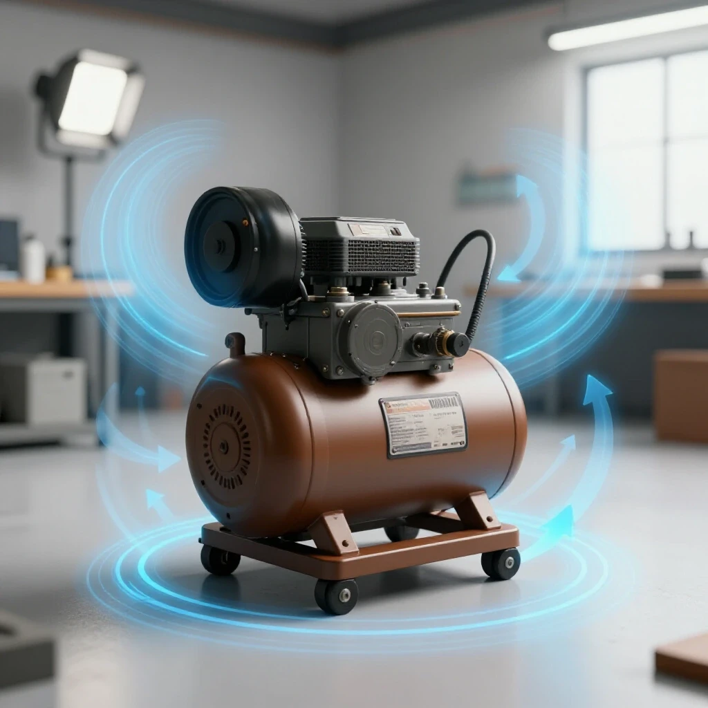
I still remember the first time I built a custom equipment base for my garage. I had spent three hours meticulously measuring and cutting angle iron, only to watch the entire frame twist like a pretzel as soon as I finished the final weld. It was a humbling lesson in the physics of metal. When you are building a cooling-efficient support for shop machinery, like a portable air compressor, you aren’t just sticking metal together. You are managing heat, tension, and airflow. A compressor that sits on the floor collects dust and runs hot, which shortens its life. By elevating it on a custom-fabricated stand, you improve air circulation and save your back.
In my thirteen years as a prototype technician, I have learned that the difference between a professional-grade project and a frustrating scrap heap lies in the preparation. This guide focuses on the practical steps to fabricate a sturdy, ventilated platform. We will cover how to keep your frame square, how to account for the thickness of your saw blade, and how to sequence your welds so the heat doesn’t ruin your hard work.
Planning Your Elevated Equipment Platform
Designing a functional shop stand requires more than just a rough sketch on a napkin. It involves calculating the load-bearing needs of your compressor and ensuring the design allows for maximum heat dissipation through the base. Proper planning prevents material waste and ensures the final structure can handle the vibration of a running motor without walking across the floor.
Before you strike an arc, you need a clear blueprint. For a standard small compressor, I usually aim for a footprint that is two inches wider than the tank’s feet on all sides. This provides stability. I prefer using 1.5-inch by 1.5-inch angle iron with a 3/16-inch thickness. It is easy to cut and provides a natural “shelf” for a mesh floor.
Sourcing Materials for Maximum Airflow
The choice of flooring for your equipment stand is the most critical factor for cooling. Solid plate steel traps heat and vibrates loudly, while expanded metal or perforated sheet allows air to move freely around the pump and motor. This airflow is vital for preventing the compressor from overheating during long cycles.
I generally recommend 9-gauge flattened expanded metal for the top surface. It is strong enough to support a 100-pound compressor but has enough open area to let air circulate. If you prefer a cleaner look, a 12-gauge perforated sheet with 1/2-inch holes works well too. Just ensure the material is weldable and free of heavy galvanized coatings, which can produce toxic fumes during the fabrication process.
The Layout and Squaring Process
A successful build starts with an accurate layout on your workbench. If your base frame is not perfectly square from the beginning, every other part of the stand will be crooked, leading to a wobbly finished product. Layout is about more than just using a tape measure; it is about using physical stops and jigs to ensure repeatability.
I always start by cleaning my work surface. Any slag or metal shavings under your workpiece will throw off your measurements. When I am setting up custom fabrication projects, I use a large framing square and a set of heavy-duty magnets to hold the pieces in place. However, magnets can sometimes pull the arc of your welder, so I use them only for the initial positioning.
Calculating Kerf for Accurate Dimensions
The term “kerf” refers to the width of the material removed by your cutting tool. If you ignore the kerf, your finished frame will be shorter than intended, often by as much as 1/8 of an inch per cut. This small error compounds quickly across four corners, leaving you with gaps that are too wide to fill with a weld.
When I use an abrasive chop saw, I account for a 1/8-inch kerf. If I am using a portable bandsaw, the kerf is usually closer to 1/16 of an inch. I always mark my cut line and then place the blade on the “waste” side of that line. This ensures the remaining piece is exactly the length specified in my cut list.
Table 1: Cutting Tool Kerf Allowances
| Tool Type | Typical Kerf Width | Best Use Case |
|---|---|---|
| Abrasive Chop Saw | 1/8 inch (3.2mm) | Fast, rough cuts on thick angle iron |
| Cold Saw | 3/32 inch (2.4mm) | Precision cuts with minimal burrs |
| Portable Bandsaw | 1/16 inch (1.6mm) | Controlled, quiet cuts in the garage |
| Plasma Cutter | 1/16 to 1/10 inch | Complex shapes or thick plate |
Managing Thermal Expansion and Weld Sequencing
Metal expands when it gets hot and contracts as it cools. This movement is the primary cause of warping in workshop jigs and fixtures. If you weld one entire side of a joint at once, the cooling metal will “pull” the uprights inward, ruining your alignment. Managing this requires a strategic approach to heat input.
The secret to a straight frame is a balanced weld sequencing layout. You want to distribute the heat evenly across the project. Instead of finishing one corner and moving to the next, I jump across the frame in a “star” pattern, similar to how you tighten lug nuts on a car wheel. This allows one area to cool down while you are working on the opposite side.
The Art of Structural Tacking
A tack weld is a small, temporary bead used to hold parts in alignment before the final welding begins. These tacks should be strong enough to resist the initial pull of the metal but small enough that they can be ground away if you need to make an adjustment. For a small compressor stand, 1/4-inch tacks are usually sufficient.
I always place my tacks on the inside of the corners first. Interestingly, the metal will pull toward the side you are welding. By tacking the inside, you can check for squareness and then “bump” the metal into place if it has moved. Once the frame is square within a 1/16-inch tolerance, I add tacks to the outside corners to lock everything down.
Table 2: Weld Sequencing for Distortion Control
| Step | Action | Purpose |
|---|---|---|
| 1 | Corner Tacks (Inside) | Initial alignment and squaring |
| 2 | Opposite Corner Tacks | Balanced restraint of the frame |
| 3 | Check Square (Diagonal) | Ensure the frame isn’t a trapezoid |
| 4 | Short Beads (Outside) | Provides structural strength with low heat |
| 5 | Opposite Side Beads | Counteracts the pull from Step 4 |
Step-by-Step Construction Log
Building a cooling-focused compressor base requires a logical progression of steps to ensure the finished product is level and stable. I follow a specific routine that I have refined over dozens of shop builds. This process minimizes errors and keeps the project moving forward without the need for rework.
- Cut the main frame members: For a standard stand, I cut four pieces of angle iron for the top frame and four for the legs. I use a 45-degree miter cut for the top frame to create a clean, boxed look.
- Deburr the edges: Use a flap disc on an angle grinder to remove the sharp burrs from the saw. This ensures the pieces fit tightly together without gaps.
- Set up the layout fixture: I use a flat welding table and a set of C-clamps. I clamp the first two pieces of the top frame against a known square edge.
- Initial Tacking: I place one small tack at the top and bottom of the miter joint. I repeat this for all four corners.
- Measure Diagonals: I measure from the top-left corner to the bottom-right, then from top-right to bottom-left. If the measurements are within 1/16 of an inch, the frame is square.
- Weld the Legs: I flip the frame over and tack the legs to the inside corners. I use a magnetic level to ensure the legs are vertical (plumb) before welding.
- Install the Floor: I drop the expanded metal or perforated sheet into the “shelf” created by the angle iron. I tack weld it every four inches to prevent rattling.
Advanced Metal Layout Tips for DIYers
When you are working in a garage, you might not have a $5,000 fabrication table. However, you can still achieve professional results by using simple metal layout tips. One of my favorite tricks is using a “jig” made of scrap wood or metal to hold pieces at a perfect 90-degree angle.
Another tip is to use a scribe instead of a Sharpie. A permanent marker leaves a line that is nearly 1/16 of an inch wide. If you cut to the left side of the line versus the right side, your piece could be off significantly. A carbide-tipped scribe or a sharpened soapstone leaves a much finer mark, allowing for more accurate square cuts.
Correcting Heat Distortion
Even with the best sequencing, some warping is almost inevitable. If you find that one leg of your stand is “toed-in” or the top frame has a slight bow, don’t panic. You can often correct this using the same physics that caused the warp: heat.
By applying heat to the opposite side of the warp with a torch and then cooling it quickly with a damp rag, you can “shrink” the metal back into position. This is a technique called flame straightening. It takes practice, but it is a vital skill for anyone doing custom fabrication projects. Alternatively, for minor adjustments, a heavy dead-blow hammer and a solid anvil surface can often nudge a leg back into alignment.
Finishing and Airflow Considerations
Once the structural welding is complete, the focus shifts to the final touches that make the stand functional. For a compressor, vibration dampening is just as important as airflow. If the metal stand is sitting directly on a concrete floor, it will create a deafening roar when the compressor kicks on.
I always weld a small flat tab to the bottom of each leg. These tabs allow me to bolt on rubber vibration isolation pads. These pads serve two purposes: they reduce noise and they prevent the stand from “walking” across the shop floor due to the motor’s vibration. Finally, I finish the stand with a coat of high-quality equipment enamel to prevent rust, making sure not to clog the holes in the perforated floor with thick paint.
Checklist for Final Assembly:
- Check all welds for porosity or cracks.
- Grind down any sharp edges or “snags” on the expanded metal.
- Verify that the compressor’s drain valve is accessible through the stand’s floor.
- Ensure there is at least 4 inches of clearance between the compressor pump and any walls for airflow.
- Install rubber feet to isolate vibration.
Conclusion
Building a well-ventilated support for your shop equipment is a project that pays off every time you flip the power switch. By focusing on accurate layouts, managing weld shrinkage, and prioritizing airflow, you create a tool that is both durable and functional. I have found that taking the extra time to calculate kerf and sequence welds makes the difference between a project I am proud of and one that stays hidden in the corner.
Remember that metal is a dynamic material. It moves, it breathes, and it reacts to heat. The more you respect those properties, the better your results will be. Start simple, measure twice, and don’t be afraid to use clamps to force the metal to obey your design.
FAQ
How do I prevent my angle iron frame from twisting during welding? The best way to prevent twisting is to use a balanced weld sequence. Never weld a full joint in one pass. Instead, use small tacks to lock the frame in square, then place short beads on opposite sides of the structure. This balances the cooling forces so they pull against each other rather than twisting the frame.
What is the best material for the floor of a compressor stand? Expanded metal (9-gauge) or perforated steel sheet is ideal. These materials provide the structural strength needed to hold the weight while allowing air to flow upward, cooling the compressor pump and motor. Avoid solid plate steel as it traps heat and increases vibration noise.
How much gap should I leave between the compressor and the wall? For proper ventilation, you should leave at least 4 to 6 inches of clearance between the compressor and any walls. This ensures that the cooling fan on the motor can pull in fresh air and push heat away from the unit.
Can I build this stand using a 110v MIG welder? Yes, a 110v MIG welder is perfectly capable of welding 3/16-inch angle iron. However, you may need to use a bevel on your joints to ensure deep penetration. I recommend using a gas-shielded wire (like ER70S-6) for the cleanest results and less cleanup.
How do I make sure the stand doesn’t wobble on an uneven garage floor? The most effective method is to add adjustable leveling feet. You can weld a threaded nut to the bottom of each leg and use a heavy-duty bolt with a rubber pad as a foot. This allows you to “dial in” the height of each leg so the stand stays perfectly level.
Why is my compressor vibrating so much on the new stand? Vibration is usually caused by “metal-on-metal” contact. Ensure you have rubber isolation pads between the compressor feet and the stand, and additional pads between the stand legs and the floor. This breaks the vibration path and significantly reduces noise.
Should I paint or powder coat the stand? For most DIYers, a high-quality spray-on enamel or “chassis black” paint is sufficient. It provides good rust protection and is easy to touch up if the stand gets scratched. Powder coating is more durable but can be expensive for a simple shop fixture.
How do I calculate the diagonal measurement to check for square? You can use the Pythagorean theorem (A² + B² = C²), but a simpler way is to just ensure the two diagonal measurements are identical. If the distance from corner A to corner D is exactly the same as corner B to corner C, your frame is square.
What size angle iron is best for a 20-gallon compressor? For a 20-gallon unit, 1.5-inch x 1.5-inch angle iron with a 3/16-inch thickness is the “sweet spot.” It offers plenty of rigidity without making the stand unnecessarily heavy or difficult to move.
Is it better to weld or bolt the compressor to the stand? Always bolt the compressor to the stand using vibration-dampening mounts. Never weld the compressor tank directly to the stand, as the heat from welding can weaken the tank’s structural integrity and lead to a dangerous failure.
(This article was written by one of our staff writers, Robert Kline. Visit our Meet the Team page to learn more about the author and their expertise.)