Is Vertical Down Welding Strong Enough for Frames? (Review)
When a structural frame fails in the field, the autopsy usually begins at the joint. I have spent nearly two decades crawling under industrial chassis and inspecting heavy equipment skeletons, and I have seen a recurring pattern. A weld looks visually perfect—smooth, consistent, and well-tapered—yet it has peeled away from the base metal like a sticker. This is the primary frustration for fabricators dealing with downward progression in vertical joints. We often trade deep penetration for speed and aesthetics, but in the world of high-stress frames, that trade-on can lead to catastrophic mechanical failure.
The core of the issue is not that the technique is inherently “bad,” but that it is often misapplied to materials that require more thermal energy than a downward pass can provide. When I troubleshoot a failed frame, I look for “cold lap,” a condition where the weld metal sits on top of the base metal without actually fusing into it. Because the arc is moving down, the molten puddle often wants to run ahead of the electrode. This creates a cushion of liquid metal that insulates the base plate from the heat of the arc, resulting in a joint that has the appearance of strength but lacks the structural integrity to handle torsional loads or vibration.
Understanding the Mechanics of Downward Weld Travel
Downward weld travel is a technique where the welder starts at the top of a vertical joint and moves the arc toward the bottom. This method is characterized by high travel speeds and a shallow, fast-freezing puddle. While it is effective for thin-gauge materials where burn-through is a concern, its application on structural frames requires a deep understanding of how gravity and arc force interact.
The physics of this process are straightforward but unforgiving. In a downward pass, gravity pulls the molten metal in the same direction as the torch. If the travel speed is not high enough to stay ahead of the puddle, the arc will strike the molten pool instead of the base metal. This significantly reduces the “digging” action of the arc. In my experience, when diagnosing a frame failure, the root cause is almost always this lack of penetration. The weld metal simply didn’t reach the root of the joint, leaving a hollow or unfused section that acts as a stress riser.
Identifying Cold Lap and Lack of Fusion in Frame Joints
Lack of fusion, often called “cold lapping,” occurs when the weld metal fails to bond with the base metal or the previous weld bead. In downward welding, this is the most common defect I encounter during a metalworking diagnostic guide review. Because the heat is distributed over a larger area of the puddle rather than focused on the root, the base metal never reaches its melting point before the filler metal covers it.
To diagnose this, I rely on a systematic approach. If a frame has already failed, I examine the “toe” of the weld. If the weld metal peels off leaving a smooth surface on the base plate, you have a classic case of lack of fusion. If the frame is still intact but you suspect an issue, I use a combination of visual inspection and non-destructive testing. Look for a “rolled” edge at the toe of the weld. A healthy weld should transition smoothly into the base metal; a cold-lapped weld will have a distinct, rounded edge that looks like it is just resting on the surface.
- Visual indicators of cold lap: Rounded weld toes, lack of “tie-in” at the edges.
- Physical testing: A “nick-break” test on a sample joint can reveal internal voids.
- Advanced diagnostics: Ultrasonic testing (UT) can identify the exact depth of fusion.
Troubleshooting Weld Porosity and Gas Coverage Failures
Troubleshooting weld porosity is a critical step when evaluating the strength of any frame. Porosity consists of small gas pockets trapped in the weld metal, which can significantly reduce the cross-sectional strength of the joint. When welding downward, the high travel speeds can create turbulence in the shielding gas, or the fast-cooling puddle can trap gases before they have a chance to escape.
In my repair logs, I’ve found that porosity in downward passes often stems from an incorrect torch angle. If the torch is angled too far upward (pushing the gas away from the puddle), atmospheric air can be sucked into the arc stream. I always check the shielding gas flow rates first. For most frame work, a flow of 25 to 35 CFH (Cubic Feet per Hour) is the baseline. If you are seeing “pinholes” on the surface, you are likely dealing with surface contamination or a gas coverage issue. If the porosity is internal, it usually points to a chemical reaction between the filler metal and mill scale or rust on the base material.
| Porosity Type | Likely Root Cause | Diagnostic Step |
|---|---|---|
| Surface Pinhole | Shielding gas turbulence or wind | Check gas flow; use a wind screen |
| Wormhole Porosity | Moisture or heavy mill scale | Clean base metal to bright white |
| Scattered Internal | High travel speed/Fast cooling | Slow down or increase heat input |
| Cluster Porosity | Gas pre-flow or post-flow issues | Test solenoid and regulator |
Assessing Thermal Distortion and Frame Misalignment
Thermal distortion is the movement of metal caused by the expansion and contraction of the heat-affected zone (HAZ). While downward welding is often praised for its low heat input, this can be a double-edged sword. Low heat input reduces warping, but if the heat is too low, the joint may not be strong enough. However, even with downward passes, improper sequencing can pull a frame out of its 0.002-inch tolerance.
When I am performing a lathe alignment checklist or checking a vehicle frame, I use a digital dial indicator to track movement. I start by establishing a mechanical baseline. I measure the squareness of the frame at four points before any welding begins. After the downward passes are completed, I measure again. If the frame has pulled more than 0.010 inches over a four-foot span, the heat distribution was uneven. To fix this, I recommend a “back-stepping” technique or alternating sides to balance the thermal stresses.
Vibrational Stress and Fatigue in Downward-Welded Structures
One of the most overlooked aspects of frame strength is how the weld handles vibrational loads. In my 15 years of diagnosing machinery, I have found that tool chatter solutions often lead back to the rigidity of the machine’s frame. If a frame is welded with shallow downward passes, it may lack the stiffness required to dampen resonant harmonics.
A weld that lacks deep penetration is essentially a “hinge” on a microscopic level. Under high-frequency vibration, these shallow joints can develop fatigue cracks. I use a smartphone vibration spectrum analyzer to look for resonant peaks in a frame. If a machine is experiencing excessive tool chatter, and the spindle backlash is within the 0.002-inch spec, the issue is often the frame’s inability to absorb energy. A downward weld that only penetrates 10% of the material thickness will have a much lower fatigue life than an upward pass with 40% penetration.
A Systematic Metalworking Diagnostic Guide for Frame Failures
When a frame cracks or a machine loses its alignment, you need a structured methodology to find the “why” before you try to apply a “how.” I follow a three-step framework: Observation, Isolation, and Variable Control.
- Observation: Document the failure. Is the crack in the center of the weld (hot crack) or at the toe (cold lap)?
- Isolation: Remove external factors. Is the machine level? Are the anchor bolts tight? If the frame is the problem, isolate the specific joint that is flexing.
- Variable Control: Change one thing at a time. If you suspect the downward pass was too cold, increase your amperage by 10% on a test piece and perform a bend test.
In one case study involving a custom-built milling stand, the operator complained of “ghost” vibrations that ruined surface finishes. After checking the spindle for 0.001-inch runout and finding it perfect, I moved to the frame. The stand had been welded entirely with downward MIG passes. Using a dye penetrant test, I found micro-cracks at every corner joint. The shallow welds couldn’t handle the 3,500 RPM harmonics of the motor. We had to gouge out the welds and re-weld them using an upward progression to ensure deep root fusion. The vibration vanished immediately.
Measuring Mechanical Baselines and Tolerances
Precision is the difference between a tool and a “toy.” When troubleshooting frame alignment, you cannot rely on a tape measure. You need a 0.001-inch dial indicator and a precision square.
- Check for Backlash: In any moving part of the frame, ensure backlash does not exceed 0.002 inches.
- Verify Squareness: Use the 3-4-5 method but scale it up with a laser level for industrial frames.
- Inspect Flatness: A precision straightedge should not allow a 0.0015-inch feeler gauge to pass under it at any point on the mounting surface.
If your downward welds are causing the frame to “twist,” you are likely putting too much heat into one side of the joint too quickly. Even though the travel speed is high, the cumulative heat can still cause the metal to contract and pull.
Testing Machine Electronics and Power Delivery
Sometimes, what looks like a weld defect is actually an electrical issue. I have seen “pulsing” in the weld bead that looked like poor operator technique but was actually a fault in the wire feeder’s motor controller. If the voltage drops more than 2-3 volts during the arc-start, your machine isn’t delivering the consistent energy required for a downward pass.
When troubleshooting weld porosity or inconsistent penetration, I always check the “ground” (workpiece lead) first. A loose ground creates resistance, measured in milliohms. If your resistance is high, the arc will be unstable. This instability is magnified in downward welding because you are already working with a sensitive puddle. I use a multimeter to check the resistance between the welder’s ground clamp and the actual joint. It should be as close to zero as possible.
Case Study: The 1/4-Inch Plate Failure
I once consulted for a shop that was building trailers for heavy equipment. They were using a downward MIG process on 1/4-inch A36 steel. They liked the speed and the lack of cleanup. However, three trailers returned with cracked tongue-to-frame joints.
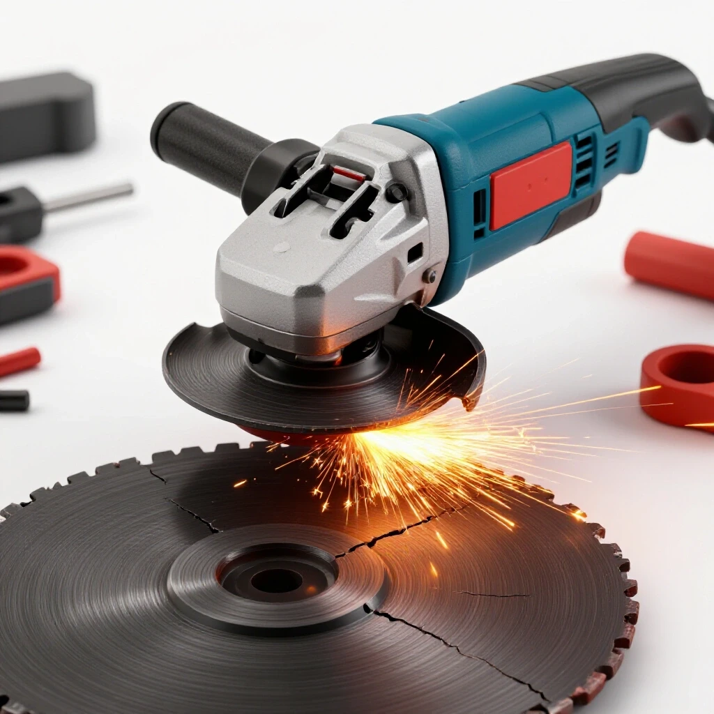
Upon inspection, I used a portable grinder to “V” out one of the failed joints. The weld metal was only bonded to the top 1/16th of the plate. The remaining 3/16ths of the joint was just touching, not fused. The downward pass had moved so fast that it “skimmed” the surface. We performed a diagnostic math exercise: at their travel speed, the heat input was only 15 kilojoules per inch. For 1/4-inch plate, they needed at least 35 kilojoules to get a reliable root. We switched them to an upward progression, which naturally slowed them down and increased the heat input, and the failures stopped.
Diagnostic Tools and Calibration Checklist
To master structural troubleshooting, you need a kit that goes beyond a welding hood. Here is the checklist I use when evaluating frame integrity and machine health:
- Digital Dial Indicator (0.0005″ resolution): For checking frame deflection under load.
- Infrared Heat Camera: To map the heat-affected zone and identify “cold spots” in the welding sequence.
- Dye Penetrant Kit: To find surface-breaking cracks that are invisible to the naked eye.
- Multimeter with Inductive Amperage Clamp: To verify the welder is actually putting out the current shown on the display.
- Precision Machinist’s Level: To ensure the frame isn’t being welded with a “built-in” twist.
Actionable Tracking Framework for Weld Quality
If you are a fabricator who wants to eliminate guesswork, you must track your variables. I recommend keeping a “Weld Log” for every major frame project.
- Material Grade and Thickness: (e.g., A36 Steel, 0.375″)
- Filler Metal Type: (e.g., ER70S-6, 0.035″)
- Gas Flow Rate: (e.g., 30 CFH C25)
- Measured Voltage and Amperage: (e.g., 19.5V, 180A)
- Travel Speed: (Measured in Inches Per Minute)
- Pre-heat Temperature: (If applicable)
By recording these, when a failure occurs, you can look back and see if the downward pass was performed within the “safe zone” for that material thickness. If you find that all your failures happened at travel speeds above 15 IPM, you have found your limit.
Conclusion: Developing a Diagnostic Mindset
Mastering the question of whether a downward pass is “strong enough” requires moving past opinions and into the realm of data. Every frame is a system. The weld is just one component. If the weld fails, it’s rarely because the technique is “illegal”; it’s because the diagnostic variables—heat, penetration, and fusion—were not balanced for the load.
Stop guessing. If you are worried about the strength of a downward weld on a structural frame, perform a “cut and etch” test. Weld a sample, cut it in half, and use a mild acid to reveal the penetration profile. If the “nugget” doesn’t reach the root, you have your answer. Troubleshooting is the process of removing the “maybe” until only the “fact” remains. Build your frames on facts, and they will never let you down.
FAQ: Structural Integrity and Downward Welding Diagnostics
Does vertical down welding provide enough penetration for 3/8-inch thick frames? Generally, no. For materials 1/4-inch and thicker, a downward pass often lacks the “staying power” to melt deep into the root. The arc tends to ride on top of the puddle, leading to lack of fusion. For structural frames of this thickness, an upward progression is usually necessary to ensure the joint can handle the design loads.
How can I tell if my downward weld has “cold lap” without cutting it? Look at the “toe” of the weld (the edge where the weld meets the base metal). If the weld metal looks like it is “beaded up” or rolling over the plate without a smooth transition, it is likely cold lapped. You can also use a dye penetrant test to see if there is a microscopic gap at the edge of the weld.
Why does my frame warp more with downward welding if the heat is lower? Distortion is not just about total heat; it’s about heat distribution. If you weld a long downward pass on one side of a frame without balancing it on the other, the rapid cooling of that thin bead can pull the frame significantly. Always use a staggered welding sequence to keep the frame within its 0.002-inch tolerance.
Can I use downward welding for “tack welding” a frame together? Yes, downward tacks are common because they are fast and produce a flat profile that is easy to weld over. However, ensure the final structural passes (ideally upward) completely consume the tacks to avoid leaving “cold spots” in your final joint.
What is the maximum thickness I should consider for a downward structural pass? In most shop environments, 3/16-inch is the “safety limit” for downward welding on critical frames. Anything thicker requires significantly more heat and arc force to reach the root, which gravity makes difficult during a downward move.
Does shielding gas type affect the strength of a downward weld? Absolutely. A gas with higher CO2 content (like 100% CO2 or a 75/25 mix) provides better penetration than high-argon mixes. If you must weld downward, using a gas that increases arc energy can help mitigate some of the lack-of-fusion risks.
How do I troubleshoot “wormhole” porosity in a vertical joint? Wormhole porosity is usually caused by moisture or heavy mill scale. Because downward welding is fast, the gas trapped by these contaminants doesn’t have time to bubble out before the metal solidifies. Clean your joints to “bright metal” and ensure your gas lines are free of moisture.
Why does my machine’s tool chatter get worse after I repair the frame? If your repair involved shallow downward welds, you may have reduced the frame’s rigidity. A “weak” joint allows the frame to flex, which changes its resonant frequency. This can amplify tool chatter. Ensure your repairs have 100% root fusion to restore the machine’s original damping characteristics.
Is it possible to get a “strong” downward weld on a heavy frame? It is possible if you use a “V-groove” joint preparation and a very high-current spray transfer mode, but this is difficult to control in a vertical position. For 90% of fabricators, the risk of an invisible fusion failure outweighs the speed benefits.
What is the best way to test a downward weld’s strength at home? The “Bend Test” is the gold standard. Weld two pieces of your frame material together using a downward pass, then put them in a vise and bend them 90 degrees with the weld at the point of the bend. If the weld “peels” or cracks at the base metal, it wasn’t strong enough.
(This article was written by one of our staff writers, Paul Whitaker. Visit our Meet the Team page to learn more about the author and their expertise.)