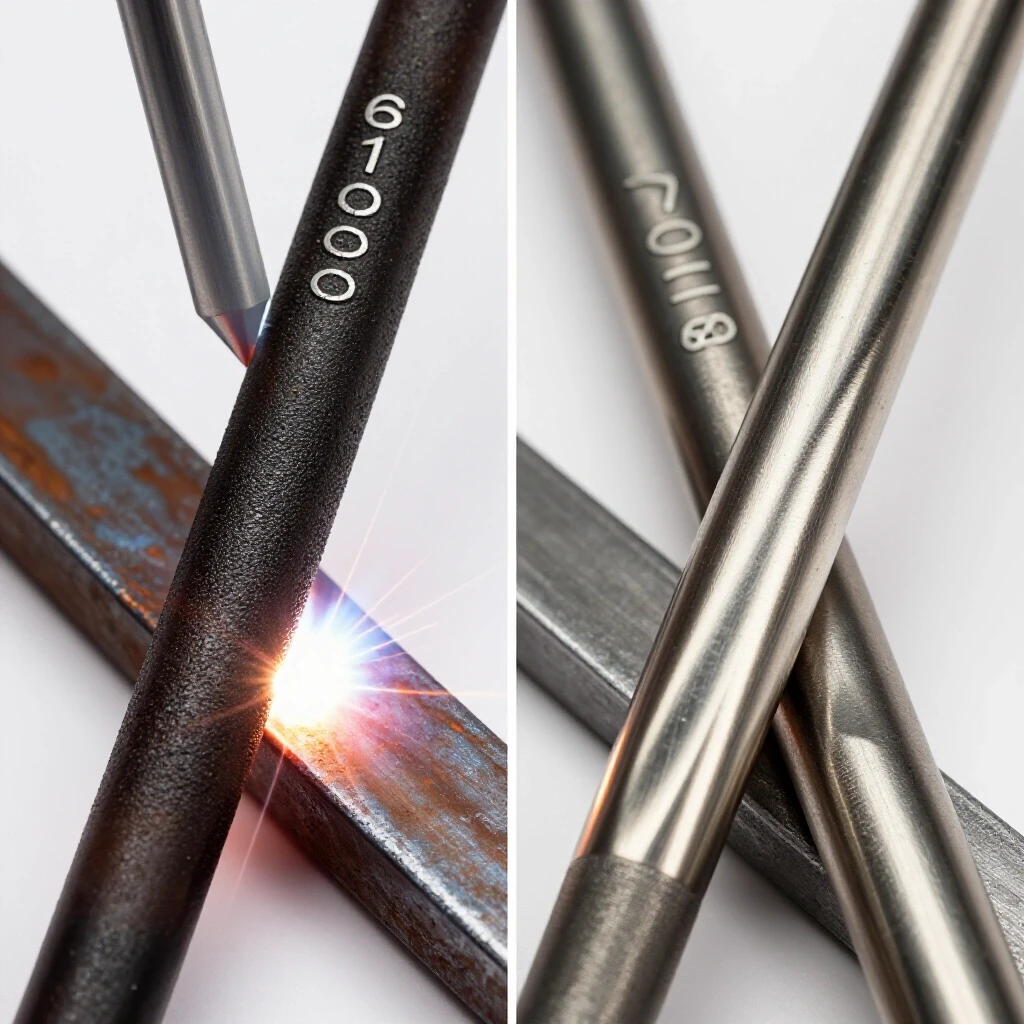
Handheld Plasma Cutter vs Oxy-Acetylene Torch (Comparison)
I remember standing over a piece of 5/8-inch mild steel three winters ago, the shop floor leaching the heat right out of my boots. I had a deadline for a heavy equipment repair, and my primary cutting tool was acting up. The arc would initiate, sputter for a second, and then die, leaving a nasty, carbon-scored divot in the plate. I could have switched to my secondary gas-based torch, but I knew that if I didn’t find the root cause of this failure, it would haunt me on the next five jobs. That afternoon was a masterclass in why we can’t just “guess” our way through equipment failures.
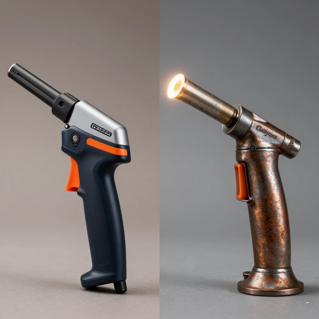
In my 18 years as a diagnostic specialist, I’ve learned that fabrication issues are rarely a single catastrophic failure. They are usually a series of small, compounding variables—moisture in a line, a worn copper orifice, or a slight drop in input voltage. Whether you are using a high-velocity ionized gas stream or a localized chemical combustion process, the goal is the same: a clean, repeatable separation of metal. When that process fails, you need a systematic framework to get back under the hood and fix it.
Mastering Thermal Severing Diagnostics
Thermal severing diagnostics involve a structured approach to identifying why a concentrated heat source is failing to penetrate or cleanly exit a workpiece. This process requires isolating the power source, the gas delivery system, and the operator’s physical movement to determine where the breakdown in energy transfer occurs.
When a cut goes south, I always start with the “Rule of Three”: Input, Tool, and Material. If you’re seeing excessive dross or a wandering arc, the first step is to check your input. For an electric-based system, this means verifying that your air compressor isn’t spitting moisture and that your circuit isn’t seeing a voltage drop under load. For a gas-based system, it means checking your cylinder pressures and ensuring your regulators aren’t “creeping,” which is when the pressure rises even when the torch is off.
I once spent four hours chasing what I thought was a faulty solenoid in a cutting unit. It turned out to be a 50-foot extension cord that was too thin for the amperage draw. The voltage drop was just enough to starve the inverter, causing the arc to flutter. Now, I always keep a digital multimeter handy to check the outlet voltage while the trigger is pulled. If you see a drop of more than 5% from the resting voltage, your power supply is the culprit, not your machine.
Evaluating the Mechanics of High-Velocity Ionized Arcs
High-velocity ionized arcs rely on a pilot arc to create a conductive path for high-amperage current to flow through a constricted gas stream. Troubleshooting this system involves inspecting the electrical continuity of the torch head and the purity of the compressed air used to create the plasma state.
One of the most common “electrical gremlins” in these units is high-frequency interference or a failure in the pilot arc transfer. If the arc starts but won’t “jump” to the workpiece, I look at the ground clamp first. In a metalworking diagnostic guide, the ground is often the most overlooked component. A weak ground creates electrical resistance, measured in Ohms. If your resistance between the work lead and the plate is higher than 0.2 Ohms, your arc will be unstable.
Troubleshooting Arc Wandering and Standoff Issues
Arc wandering occurs when the ionized stream is not perfectly centered or when the magnetic field is disrupted by the surrounding metal. This is often caused by a “blown-out” nozzle where the center hole has become oblong. Even a 0.005-inch deviation in the nozzle orifice can cause the arc to deflect at an angle, leading to a beveled cut.
- Check the swirl ring for cracks or clogged holes.
- Verify that the electrode has no more than 1/16-inch of “pit” depth.
- Ensure the standoff distance is maintained at exactly 1/8-inch for manual cutting.
Addressing Moisture Contamination in Air Lines
Moisture is the enemy of ionized gas cutting. When water enters the torch head, it expands rapidly into steam, disrupting the arc’s conductivity and rapidly eroding the copper consumables. I’ve seen brand-new nozzles destroyed in ten minutes because of a saturated desiccant filter. If you see green or black soot inside your nozzle, you have a moisture problem.
Troubleshooting Chemical Combustion and Pre-heating Efficiency
Chemical combustion cutting uses a fuel gas and oxygen to bring steel to its “kindling temperature” before a high-pressure oxygen stream oxidizes the metal. Diagnosing failures in this process usually involves analyzing the flame chemistry and the mechanical cleanliness of the torch tip.
When I’m working with a gas torch, the “pop” or “backfire” is the most common frustration. This usually happens because the tip is too close to the work, causing the gas to back up, or because the tip is overheated. A backfire is a warning; a flashback, where the flame travels into the hose, is a catastrophe. Systematic metal fabrication fixes for this involve checking for “burrs” inside the tip and ensuring your oxygen-to-fuel ratio is perfectly neutral.
Identifying Flame Imbalance and Tip Clogging
A neutral flame has a sharp, inner cone. If that cone is ragged or “feathery,” you have an excess of fuel gas. If the flame is loud and the cone is short and purple, you have too much oxygen. I use a tip cleaner—a set of small, serrated wires—to ensure the pre-heat holes are uniform. If one hole is clogged, the plate will heat unevenly, leading to a jagged start.
- Inspect the “seats” where the tip meets the torch head for carbon buildup.
- Check the regulator diaphragms for “chatter,” which causes a pulsing flame.
- Verify that the oxygen pressure is sufficient to clear the kerf—usually 25-40 PSI for 1/2-inch plate.
Managing Heat-Affected Zones and Warping
One of the biggest challenges with gas-based cutting is the large Heat-Affected Zone (HAZ). Because the process relies on chemical oxidation, the surrounding metal stays hot for longer. If you’re seeing material warping, it’s a sign that your travel speed is too slow or your pre-heat flame is too aggressive. I recommend a “skip-cutting” technique for long sections to distribute the thermal load across the part.
Identifying Root Causes of Dross and Edge Non-Conformity
Dross is the solidified, oxidized metal that clings to the bottom of a cut. It is a primary indicator of a process out of balance, whether it’s caused by incorrect travel speed, improper gas pressure, or a mismatch between the heat source and the material thickness.
In my experience, dross tells a story. “High-speed dross” is usually thin and hard to remove, looking like a weld bead on the bottom edge. “Low-speed dross” is thick, globular, and usually breaks off easily. If you’re seeing dross on one side of the cut but not the other, your torch is likely tilted, or your nozzle is worn on one side. This is where a mechanical troubleshooting step like checking your “square” becomes vital.
| Fault Symptom | Likely Root Cause | Diagnostic Metric |
|---|---|---|
| Top Edge Rounding | Travel speed too slow or torch too high | Target 1/16″ standoff |
| Heavy Bottom Dross | Travel speed too slow | Increase speed by 10% |
| Sinuous/Wavy Cut | Travel speed too fast or shaky hands | Use a straight-edge guide |
| Beveled Cut Edge | Worn nozzle or tilted torch | Check nozzle orifice for roundness |
| Incomplete Penetration | Insufficient amperage or oxygen pressure | Check PSI/Amps against chart |
Managing Gas Flow and Consumable Lifespans
Consumables are the “tires” of your cutting equipment; they wear down and must be replaced to maintain performance. Troubleshooting consumable life involves looking at gas flow rates, piercing techniques, and the cleanliness of the material being cut.
For ionized gas systems, the “pierce height” is critical. If you start a cut with the torch too close to the plate, the molten metal splashes back into the nozzle, instantly ruining it. I always set my pierce height at double the cutting height (roughly 1/4-inch) and then drop down once the arc has punched through. This simple mechanical adjustment can triple the life of your electrodes.
Gas Flow Benchmarks for Optimal Performance
- Ionized Gas Units: Require a steady flow of 4.5 to 6.0 SCFM (Standard Cubic Feet per Minute) at 90-110 PSI. If your compressor can’t keep up, the arc will starve and sputter.
- Combustion Torches: Require specific PSI settings based on tip size. For a #1 tip cutting 1/2-inch steel, I typically run 30 PSI Oxygen and 5-7 PSI Fuel Gas.
Analyzing Tool Chatter and Vibrational Damage
While we don’t think of handheld torches as having “chatter” like a lathe, the vibration from an unsteady hand or a vibrating worktable can ruin a cut. I’ve seen fabricators struggle with “stepped” cuts that look like tool marks. This is often caused by the operator’s breathing or a lack of a steady rest. I always use a “drag shield” or a dedicated guide to isolate the tool from my own physiological tremors.
Field Reliability and Power Supply Constraints
When you’re out in the field, diagnostics become twice as hard because you lose the “controlled environment” of the shop. You’re dealing with portable generators, wind interference, and long hose runs. Troubleshooting these issues requires a “system isolation” mindset.
If I’m using a portable generator to power an inverter-based cutting unit, I have to ensure the generator has “clean” power. Many older generators have high Total Harmonic Distortion (THD). An inverter unit might see this as “dirty” power and refuse to strike an arc to protect its internal capacitors. In these cases, a gas-based combustion torch is often the more reliable field tool because it requires zero electrical input.
Portability and Setup Logistics
- Cylinder Safety: Always secure gas cylinders in a vertical position. If an acetylene tank is laid flat, the acetone inside can be drawn into the regulator, causing a fire hazard.
- Hose Integrity: For long runs (over 50 feet), you must account for pressure drop. I increase my regulator pressure by 2-3 PSI for every extra 25 feet of hose.
- Grounding in the Field: When working on a trailer or a large structure, ensure your ground clamp is as close to the cut as possible to avoid “stray current” that can damage vehicle electronics or bearings.
Mitigating Thermal Hazards and Workshop Safety Risks
Safety diagnostics involve identifying potential failure points in your protective equipment and environment. This includes checking for gas leaks, ensuring proper ventilation for fumes, and protecting against high-voltage electrical shocks.
I once worked with a guy who thought he had a “porosity” issue in his welds, but it turned out his cutting process was leaving a heavy carbon film on the edges of the metal. This film was contaminating his weld pool. The “fix” wasn’t a change in his welding technique, but a change in how he cleaned the metal after cutting. If you’re using a gas torch, you must grind the oxide layer (the “scale”) off the edge before you even think about striking a welding arc.
Electrical and Respiratory Safety Checklist
- Insulation Check: Inspect the torch lead for nicks. High-frequency start units can “jump” through small cracks in the insulation and give you a nasty shock.
- Fume Extraction: Both processes produce hazardous fumes. Ionized gas cutting produces ozone and nitrogen oxides, while gas cutting produces carbon monoxide. Always work in a cross-draft.
- Flash Protection: Use a #5 shade for gas cutting and a #9 to #11 shade for ionized gas cutting. The UV radiation from a plasma arc is significantly more intense than a gas flame.
Real-World Case Study: The Sputtering Arc
Last year, a colleague brought me a cutting unit that was “pulsing.” Every three inches of travel, the arc would dim and the cut would fail to go through. We started by replacing the consumables—no change. We checked the air pressure—steady at 100 PSI.
I decided to perform a “voltage drop test” on the internal solenoid. Using a multimeter, I discovered that when the solenoid opened, the voltage to the control board dropped from 24V to 18V. The culprit was a loose spade connector on the internal transformer. It was a 0.002-inch gap that was causing a high-resistance connection. We crimped the connector, and the unit ran perfectly. This is why we never assume the “big” components are dead until we’ve checked the “small” connections.
Actionable Tracking Framework: The 5-Step Diagnostic Log
To avoid repeating the same mistakes, I recommend keeping a small notebook by your cutting station. When a tool fails, document the following:
- Symptoms: (e.g., “Arc pops and dies,” “Excessive dross on left side.”)
- Environment: (e.g., “Humid day,” “Running on 50ft extension cord.”)
- Consumable Condition: (e.g., “Electrode has 0.040″ pit,” “Nozzle is slightly oval.”)
- Variable Changes: (e.g., “Increased PSI from 90 to 110,” “Cleaned ground clamp.”)
- Result: (e.g., “Clean cut achieved at 15 IPM.”)
Finalizing the Repair and Moving Forward
Mastering these tools isn’t about knowing every technical spec in the manual; it’s about developing an “ear” and an “eye” for the process. You should be able to hear the difference between a healthy, “hissing” plasma arc and a struggling one. You should be able to see the difference between a “oxidizing” gas flame and a “carburizing” one.
If you’re currently struggling with a machine that isn’t performing, stop the work. Don’t try to “power through” a bad cut. Every inch of bad cut is more grinding and more wasted material. Go back to your baselines. Check your pressures, check your orifices, and check your grounds. In 90% of the cases I’ve diagnosed, the solution was a simple mechanical adjustment that had been overlooked in the rush to get the job done.
FAQ: Troubleshooting Thermal Severing Tools
Why does my plasma arc sputter even with brand-new consumables? Sputtering is usually a sign of “dirty” air or a fluctuating power supply. Check your air filters for moisture or oil. Even a tiny amount of compressor oil can contaminate the arc. Also, verify that your work clamp is on clean, shiny metal, not over rust or paint.
How can I tell if my oxy-acetylene tip is shot? Look at the pre-heat flames. They should all be the same length and shape. If one is longer or skewed, the tip is dirty or deformed. If the center oxygen hole is no longer perfectly round, you will get a turbulent stream that creates a jagged cut.
What causes the “curved” bevel on the bottom of my cuts? This is often caused by excessive travel speed. The bottom of the arc or flame “lags” behind the top, creating a curved trailing edge. Slow down your travel speed and ensure your torch is perfectly perpendicular to the plate.
Is it normal for the electrode to have a small pit in the center? Yes, a small pit (up to 1/16-inch or about 1.5mm) is normal for a used electrode. However, once the pit gets deeper or the hafnium insert is gone, the arc will become unstable and can eventually damage the torch head.
Why is my gas torch “popping” every time I get close to the metal? This is a “backfire.” It happens when the tip gets too hot or the gas flow is too low to keep the flame pushed out. Clean the tip, increase your gas pressures slightly, and try to keep a consistent 1/8-inch to 1/4-inch standoff.
Why does plasma cutting leave a harder edge than gas cutting? The ionized gas process uses an extremely high temperature (up to 30,000°F) which can cause “nitriding” on the edge if you use shop air (which is 78% nitrogen). This creates a very hard, thin layer that can be difficult to grind or drill.
Can I use a standard air compressor for plasma cutting? Yes, but it must meet the SCFM requirements of the torch. Most small “pancake” compressors cannot provide the 5-6 SCFM needed for continuous cutting. If the compressor runs constantly, it will get hot and send moisture down the line.
What is the best way to prevent warping on thin sheet metal? The best way is to minimize heat input. Use the fastest travel speed possible that still achieves a full cut. If using a gas torch, you may need to use a smaller tip and “stitch cut” to allow the metal to cool between sections.
How do I diagnose a faulty regulator? Set your regulator to a specific pressure (e.g., 40 PSI) and watch the needle. If the pressure slowly rises while the torch is not in use, the internal seat is leaking (creeping). This is a safety hazard and the regulator should be serviced or replaced.
Why am I getting “top dross” on my plasma cuts? Top dross (splatter on the top of the plate) is usually caused by having the torch too high (excessive standoff) or traveling too fast. The arc isn’t “blowing” the molten metal through the kerf, so it swirls back up to the top.
(This article was written by one of our staff writers, Paul Whitaker. Visit our Meet the Team page to learn more about the author and their expertise.)