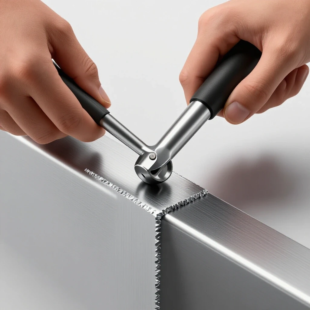
How to Notch Round Tubing Accurately With Hole Saw (DIY Fix)
In my eighteen years walking the concrete floors of fabrication shops, I have learned that the most frustrating problems are rarely the loudest ones. They are the subtle, creeping errors—the slight vibration in a drill press spindle or the 0.010-inch misalignment in a workholding jig—that turn a simple task into a scrap-metal nightmare. I remember a specific job where we had to prep forty structural joints using a basic hole saw setup. On the first five, the fitment was so loose you could throw a cat through the gaps. It wasn’t a lack of effort; it was a lack of a systematic diagnostic approach.
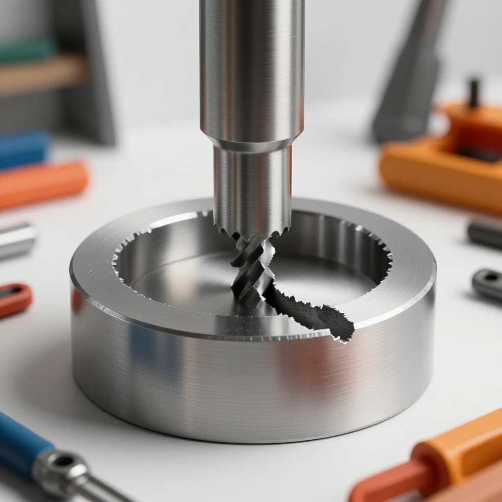
When you are trying to achieve a tight radius on the end of a pipe using a saw, you are fighting physics. You are asking a thin, cylindrical blade to enter a curved surface at an angle. Without a structured way to isolate variables like tool chatter, spindle play, and geometric offset, you will find yourself chasing your tail. My goal is to move you away from the “trial and error” method and toward a millwright’s mindset: observe, isolate, and calibrate.
Establishing the Diagnostic Framework for Precision Pipe Coping
A diagnostic framework is a structured mental map used to identify the root cause of a mechanical failure. It involves breaking a system down into its individual components—the machine, the tool, and the workpiece—to ensure each is operating within its specified mechanical tolerances before the first cut is even attempted.
When a cut goes wrong, most people blame the saw. In reality, the saw is usually just the messenger. To find the real culprit, I use a process of elimination. I start with the machine’s foundation. If you are using a drill press or a dedicated fixture, you must check for spindle runout. Runout is the degree to which a rotating tool deviates from its center axis. If your spindle has a runout of more than 0.005 inches, your hole saw will “walk” across the tube, creating an oval-shaped notch rather than a clean radius.
I recommend using a dial indicator to map the diagnostic path. Attach the indicator to the machine table and place the tip against the inside of the spindle or the outside of the saw arbor. Rotate it by hand. If you see the needle jumping, you have found your first variable. Building on this, you must also look at the rigidity of your setup. A setup that flexes under pressure is a setup that fails.
| Component | Tolerance Goal | Diagnostic Tool |
|---|---|---|
| Spindle Runout | < 0.005 inches | Dial Indicator |
| Quill Backlash | < 0.002 inches | Feeler Gauges |
| Table Squareness | 90° +/- 0.1° | Precision Square |
| Workpiece Movement | 0.000 inches | Torque Wrench / Clamps |
Identifying and Dampening Tool Vibration Harmonics
Tool vibration harmonics, often called chatter, occur when the cutting frequency of the saw teeth matches the natural resonant frequency of the machine or the workpiece. This creates a self-exciting loop that results in a rough surface finish, broken saw teeth, and inaccurate geometry in the tube profile.
I have spent countless hours tracking down “electrical gremlins” that turned out to be nothing more than mechanical resonance. When a hole saw hits a round tube, it doesn’t engage all teeth at once. This interrupted cut creates a rhythmic impact. If the speed (RPM) is too high, these impacts happen so fast that the tube begins to sing—that high-pitched squeal we all know. This is a sign that the energy is not going into cutting the metal; it is going into vibrating the machine.
To resolve this, I use a technique called variable control. Start by lowering the RPM. For a 1.5-inch hole saw in mild steel, I typically aim for 150 to 200 RPM. If the chatter persists, I look at the “overhang.” This is the distance from the chuck to the cutting edge. The longer the extension, the more leverage the vibration has. Interestingly, adding mass to the tube—such as a heavy-duty clamp near the cut site—can shift the resonant frequency and kill the chatter.
- Observation: Look for “scalloped” marks on the edge of the cut.
- Isolation: Change only one variable at a time (Speed, then Feed, then Rigidity).
- Fix: Use a cutting lubricant to reduce friction and dampen the harmonic waves.
Mechanical Alignment and Spindle Backlash Diagnostics
Spindle backlash refers to the “slop” or play between the gears or the quill and the machine housing. In the context of creating a radius on a tube, backlash allows the saw to pull itself into the material faster than intended, leading to a seized blade or a distorted cut profile.
In my experience, many intermediate fabricators overlook the quill lock. When you are feeding a saw into a curved surface, the lateral forces are immense. If the quill has 0.002 inches of play, that saw will tilt. This tilt changes the angle of the notch, meaning your tubes won’t line up when you go to fit them together. I always perform a “push test.” With the machine off, I grab the chuck and try to move it side-to-side. If I can feel a “click,” the backlash is too high.
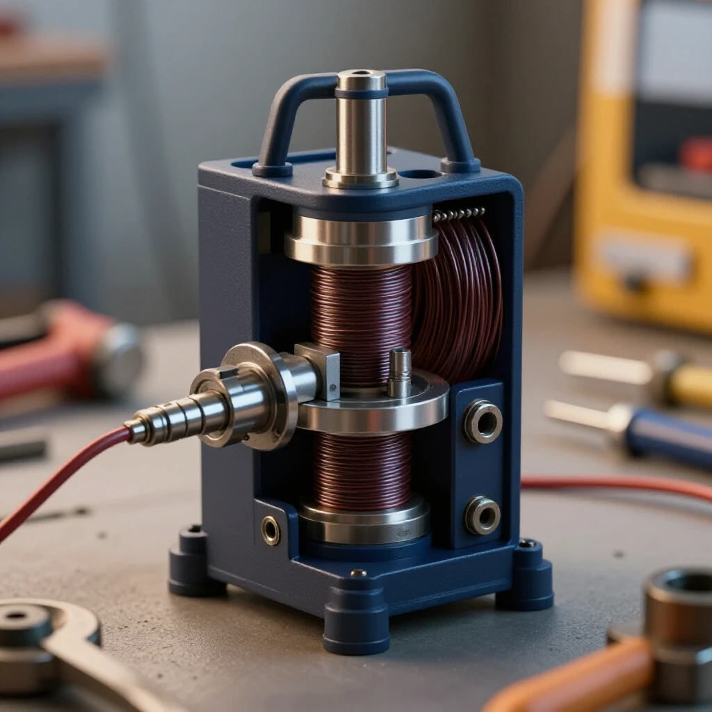
To fix this, you may need to adjust the gib screws on your drill press or use a dedicated jig that supports the saw arbor with bearings. A bearing-supported arbor is a game-changer because it isolates the saw from the machine’s internal tolerances. As a result, the saw stays on a fixed path regardless of how much the drill press wants to flex.
Measuring Vertical and Horizontal Misalignment
Misalignment is often the hidden cause of a “bad” saw. If the centerline of the hole saw is not perfectly aligned with the centerline of the tubing, the notch will be “offset.” This results in a joint that is rotated to one side. I use a simple centering trick: I lower the saw until it just touches the top of the tube. I then use a digital caliper to measure the distance from the edge of the saw to the edge of the tube on both sides. If the numbers aren’t identical, the workholding needs to be shifted.
Geometric Precision and Calculating Offset Errors
Geometric precision in tubing refers to the mathematical accuracy of the cut’s angle and depth. Even a one-degree error over a two-inch diameter pipe can create a gap large enough to compromise the structural integrity of the final assembly.
One of the most common issues I see is the “shallow notch.” This happens when the saw doesn’t travel far enough through the diameter of the tube. To diagnose this, you need to understand the relationship between the saw diameter and the tube diameter. If you are joining a 1.5-inch tube to another 1.5-inch tube, the hole saw must be exactly 1.5 inches. However, if the saw is worn or has a heavy set to the teeth, it might cut a 1.510-inch hole. This tiny difference creates a “rocking” fit.
I recommend using a paper template before you ever touch metal. There are many online calculators where you can input your tube diameters and angles, print a wrap-around template, and mark the cut line. This gives you a visual baseline. If your saw isn’t following that line, you know the issue is mechanical (vibration or alignment) rather than mathematical.
- Verify Tool Diameter: Measure the actual cutting width of the hole saw with calipers.
- Mark the Centerline: Use a V-block and a height gauge to scribe a line down the length of the tube.
- Check the Angle: Use a digital protractor to verify the angle of the tube relative to the saw arbor.
Troubleshooting Workholding and Fixture Rigidity
Workholding rigidity is the ability of a clamp or jig to resist the forces of machining without moving. In pipe coping, the workpiece is a hollow cylinder, which is notoriously difficult to grip without crushing or allowing it to spin under the torque of the saw.
I once worked on a project where the notches were consistently coming out “smeared.” It looked like the metal was being pushed rather than cut. After an hour of checking the motor and the saw, I realized the tube was rotating just a fraction of a degree inside the vise. The vibration of the saw was “walking” the tube. This is why I advocate for the use of specialized tube notches or V-jaw inserts.
A standard flat-jaw vise only contacts a round tube at two points. This is a recipe for failure. By using a V-block, you create four points of contact, which significantly increases the friction and stability. If you are seeing tool chatter, check your clamping pressure. However, be careful—over-tightening can deform thin-walled tubing, making it impossible to get a clean fit.
- Mechanical Troubleshooting Step: Apply a small mark with a paint pen across the tube and the vise jaw. After the cut, if the lines don’t match, your workholding failed.
- Metric: For steel tubing, a clamping force that resists 50 lb-ft of torque is usually sufficient for a hole saw operation.
Electrical and Motor Performance Testing
Electrical diagnostics in the workshop involve checking that the motor is receiving the correct voltage and current to maintain a constant speed under load. If the motor “bogs down” or slows during a cut, the feed-per-tooth increases, which can snap the saw teeth or cause the tool to seize.
I’ve seen many fabricators struggle with what they thought were dull saws, only to find out they were running their drill press on a 50-foot extension cord that was too thin. This causes a voltage drop. When the saw hits the metal, the motor tries to pull more current to maintain speed, but the thin cord can’t deliver it. The voltage drops, the torque disappears, and the saw stalls.
To test this, I use a multimeter to check the voltage at the outlet while the machine is running under load. If you see a drop of more than 3% to 5%, you have a power supply issue. Furthermore, check the motor’s heat. An overheating motor is often a sign of “back-EMF” issues or a failing capacitor, both of which will lead to inconsistent RPMs and poor cut quality.
Motor Diagnostic Checklist
- Voltage Check: Ensure the motor receives 115V or 230V (+/- 10%) while cutting.
- Amperage Draw: Use a clamp meter to see if the motor is exceeding its “Full Load Amps” (FLA) rating.
- Belt Tension: In a drill press, a slipping belt mimics a motor failure. Ensure the belt has about 0.5 inches of deflection.
- RPM Consistency: Use a handheld laser tachometer to verify the spindle speed matches the pulley chart.
Case Study: Resolving the “Walking” Saw Issue
A few years ago, a colleague was struggling with a setup where the hole saw would skip across the surface of the pipe before biting. This “walking” destroyed the first 1/8th inch of the cut and made the joint unusable. We treated it like a crime scene.
First, we checked the saw’s pilot bit. It was slightly bent—only 0.015 inches—but that was enough to create an eccentric rotation. Second, we looked at the entry angle. He was trying to start a 45-degree notch on a 2-inch pipe. The saw teeth on one side were hitting the metal long before the other side. This created an unbalanced lateral force.
Our fix was systematic. We replaced the pilot bit with a high-speed steel (HSS) stub drill for more rigidity. Then, we adjusted the feed rate. Instead of forcing the saw, we let it “kiss” the surface until a full circular groove was established. This created a track for the saw to follow, eliminating the walking entirely. It was a lesson in patience and mechanical alignment.
Actionable Tracking Framework for Precision Cuts
To avoid repeating mistakes, I recommend keeping a simple log of your setups. This is especially helpful if you find a combination of speed and pressure that works perfectly.
| Date | Material/Size | Saw RPM | Lubricant Used | Notes on Vibration |
|---|---|---|---|---|
| 10/12 | 1.75″ x .095 Wall | 140 | Sulfur-based oil | Zero chatter; tight fit |
| 10/14 | 1.25″ x .120 Wall | 210 | Dry | Heavy squeal; reduced RPM |
By recording these variables, you move from “guessing” to “knowing.” You start to see patterns. For instance, you might notice that your 2-inch saw always vibrates more than the others. This could lead you to inspect the arbor for that specific saw, where you might find a microscopic burr preventing it from seating flat.
Conclusion: The Path to Masterful Fabrication
Mastering the art of creating precise radii in tubing with a hole saw is not about having the most expensive tools. It is about having the most disciplined process. When you encounter a problem—whether it is a jagged cut, a stalled motor, or a misaligned joint—don’t just try again and hope for a better result. Stop. Observe the machine. Isolate the vibration. Test the alignment.
By following these systematic diagnostic steps, you turn every failure into a data point. You begin to understand the language of your machinery, from the sound of the harmonics to the feel of the spindle backlash. This methodical approach is what separates a hobbyist from a true fabricator. Take the time to calibrate your equipment, secure your workpieces, and monitor your electrical performance. The result will be clean, tight-fitting joints that make the rest of your fabrication process seamless.
FAQ: Troubleshooting Precision Tube Coping
Why does my hole saw keep catching and stalling the drill? This is usually caused by a combination of too much feed pressure and too high an RPM. When the saw teeth dig in too deep, the torque required to turn the saw exceeds the motor’s capacity. Reduce your speed and use a lighter touch. Also, ensure your workpiece is clamped rigidly; if the tube moves even slightly, it can “pinch” the saw blade.
How do I stop the saw from vibrating so loudly? Vibration, or chatter, is a sign of resonance. You can break this cycle by changing the RPM, using a heavier lubricant, or increasing the rigidity of the setup. Try clamping a piece of scrap metal to the tube near the cut to act as a dampener. If the saw is extended far out of the chuck, try to shorten that distance.
What is the best way to center the saw on the tube? The most accurate DIY method is to use a “center finder” or a V-block. Alternatively, lower the saw until it just grazes the tube. Measure the distance from the saw’s edge to the tube’s edge on both sides with a caliper. Adjust the tube until those measurements are equal.
Why are my notches coming out at the wrong angle? This is typically an alignment issue between the vise and the drill spindle. Even if your vise says 45 degrees, the drill table itself might be tilted. Use a digital angle finder to check the tube’s angle relative to the actual saw arbor, not the machine’s base.
Can I use a hand drill for this process? While possible, it is extremely difficult to maintain the necessary rigidity. If you must use a hand drill, you need a high-quality notching jig that guides the saw arbor. Without a guide, the saw will almost certainly “walk” and create an inaccurate cut.
How often should I replace my hole saw? A saw needs replacement when the “set” of the teeth is gone or if the teeth are rounded. If you notice the saw is getting hot very quickly or requires significantly more pressure to cut, it is likely dull. Using cutting oil will extend the life of your saw by 300% or more.
What should I do if the saw “walks” at the start of the cut? Ensure your pilot bit is sharp and perfectly straight. If you are starting at a sharp angle, use a center punch to give the pilot bit a starting point. Sometimes, removing the pilot bit and using a rigid jig with a bearing-supported arbor is the only way to prevent walking on steep angles.
Why does the motor on my drill press get hot during long cuts? Heat is usually a sign of electrical resistance or mechanical overload. Check that you aren’t using a long, thin extension cord. Also, ensure the motor’s cooling fan is clear of dust. If the motor is struggling to maintain RPM, you are likely feeding the saw too fast.
Is there a specific type of hole saw that works best? Bi-metal hole saws with a variable tooth pitch (e.g., 4/6 TPI) are generally best for tubing. The variable pitch helps break up the harmonic vibrations that cause chatter, leading to a smoother finish.
How do I measure the depth of the notch accurately? Measure from the highest point of the radius to the end of the tube. Use a marking gauge or a caliper set to the desired length. Remember to account for the thickness of the saw blade itself when marking your start point.
(This article was written by one of our staff writers, Paul Whitaker. Visit our Meet the Team page to learn more about the author and their expertise.)