How to Align and Gap Steel Pipes Before Welding (DIY Guide)
I have spent the last 18 years in the grease and grit of industrial fabrication mills and custom repair shops. In that time, I have learned that the most frustrating failures rarely happen during the final weld. Instead, they are born in the quiet moments of preparation. I remember a specific project involving a custom cooling manifold where we struggled with persistent tool chatter and vibrational damage in the mounting brackets. After two days of troubleshooting the lathe and the motor controllers, I realized the root cause was a 0.040-inch misalignment in the initial pipe fit-up. That tiny offset created a harmonic imbalance that vibrated through the entire assembly.
When you are working in a home shop or a small fabrication space, the temptation is to “fix it in the weld.” We assume that a little extra filler wire can bridge a sloppy gap or that a hammer can beat a pipe back into alignment after it is tacked. This is a trap. Systematic troubleshooting starts with the mechanical baseline. If your geometry is off by a fraction of an inch before you strike an arc, the thermal stress of the welding process will only amplify that error. This guide focuses on the analytical steps required to position and space mild steel pipes under 4 inches in diameter to ensure structural integrity and a clean finish.
Establishing a Systematic Approach to Joint Fitting
Joint fitting is the process of physically arranging two metal components so they meet at the correct orientation and distance for a successful fusion. This phase requires verifying the structural integrity and cleanliness of the metal surfaces before any physical positioning occurs. It sets the baseline for the entire build, ensuring that subsequent mechanical adjustments are made on a stable foundation.
In my diagnostic work, I treat every joint as a mechanical system. If a system fails, I look at the variables. For pipe fitting, those variables are cleanliness, squareness, and uniformity. Before you even think about clamps or spacers, you must address the pipe ends. A pipe cut with a portable bandsaw might look straight, but a quick check with a precision square often reveals a 1- or 2-degree deviation.
I use a simple isolation test: place the two pipe ends together on a flat surface and rotate one. If the gap between them wobbles or changes size, your ends are not square. This is a common source of troubleshooting weld porosity later on, as uneven gaps lead to inconsistent heat distribution and atmospheric contamination.
- Clean the base metal at least 1 inch back from the edge using a flap disc.
- Remove all mill scale, rust, and oils to prevent hydrogen embrittlement.
- Verify the squareness of the cut using a combination square or a dedicated pipe centering tool.
- Deburr the inside diameter (ID) and outside diameter (OD) to ensure the pieces sit flush.
Eliminating Axial Offset and Angular Misalignment
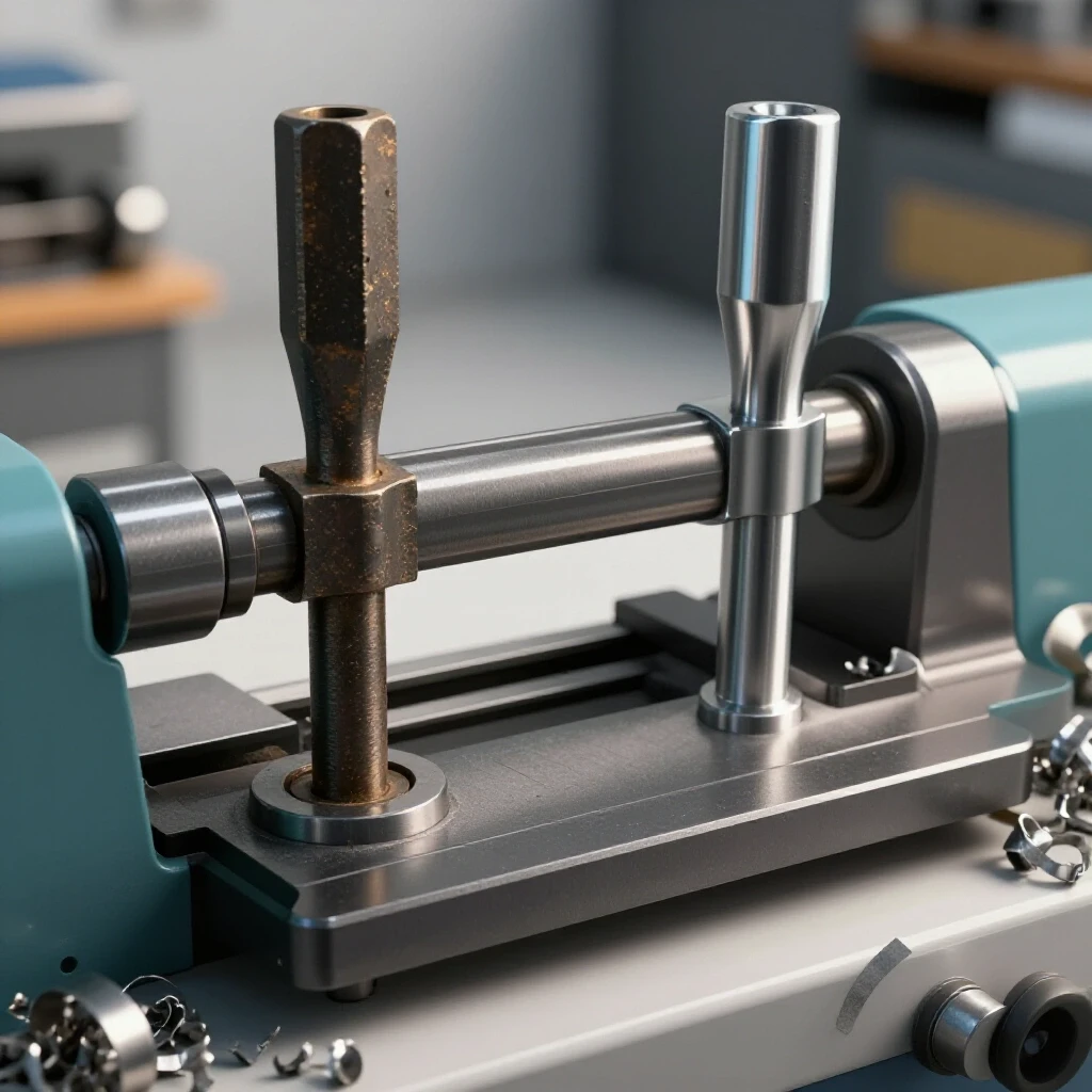
Axial offset, often called “Hi-Lo” in the industry, occurs when the centerlines of two cylindrical sections do not meet perfectly. Angular misalignment involves the pieces meeting at the wrong angle, often caused by poor clamping or thermal pull. Correcting these requires precision tools to ensure the force of the weld does not pull the assembly out of spec.
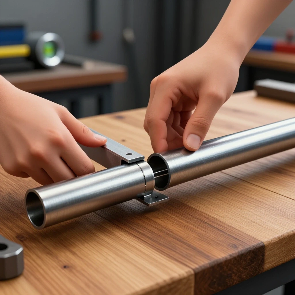
When I am diagnosing a structural failure in a frame, I often find that the fabricator ignored a 0.030-inch axial offset. In a 2-inch pipe, that offset creates a stress riser. To solve this, I rely on mechanical troubleshooting steps that involve rigid fixturing. A piece of angle iron is one of the most effective, low-cost tools for this. By nesting both pipes into the “V” of the angle iron, you force their centerlines to coincide.
Building on this, you must account for the “draw” of the weld. As the molten metal cools, it shrinks and pulls the pipes toward the weld side. If you align your pipes perfectly at 90 degrees and weld only one side, you will likely end up at 88 degrees. I recommend using a digital protractor to check your angles before and after tacking.
| Alignment Error | Root Cause | Diagnostic Check | Permanent Fix |
|---|---|---|---|
| Axial Offset (Hi-Lo) | Uneven pipe wall thickness or poor clamping | Use a straightedge across the joint; look for a “step” | Use V-blocks or angle iron jigs to center the OD |
| Angular Deviation | Non-square cuts or thermal pull | Check with a digital angle finder or square | Recut ends square; use balanced tacking sequences |
| Rotational Slip | Loose fixtures or lack of witness marks | Scribe a line across the joint before moving | Use “bridge tacks” or heavy-duty pipe clamps |
Managing the Root Opening for Consistent Penetration
The root opening, or the gap between the two pipe ends, is the space that allows the weld to penetrate the full thickness of the material. This gap must be uniform around the entire circumference to ensure even heat dissipation and prevent the buildup of internal stresses. Inconsistent gaps are a leading cause of metalworking diagnostic errors.
I have seen many fabricators struggle with “burn-through” on one side of a pipe and “lack of fusion” on the other. This is almost always a gap issue. If the gap is too tight, the arc cannot reach the root. If it is too wide, the puddle falls through. For pipes under 4 inches, I typically aim for a gap of 3/32 of an inch, which is roughly the thickness of a standard welding rod core.
To maintain this gap, I use “spacers” or “gap rods.” You can bend a piece of TIG wire into a “U” shape and hang it between the pipes. This ensures that as you tighten your clamps, the pipes don’t crush together. Interestingly, the gap also acts as a vent for gases. A closed gap can trap contaminants, leading to the very porosity issues we try to avoid.
- Gap Width: 1/16″ to 1/8″ depending on wall thickness.
- Uniformity: Use a feeler gauge or a piece of wire to check the gap at four points (12, 3, 6, and 9 o’clock).
- Tool Tip: Use a dedicated “gap tool” or a modified screwdriver to pry the joint open or closed during the tacking process.
Why Thermal Distortion Ruins Alignment and How to Isolate It
Thermal distortion is the physical warping of metal caused by the localized heating and cooling of the welding process. This phenomenon can pull perfectly aligned pipes out of position in seconds. Mastering the control of this distortion is essential for any metalworker looking to resolve mechanical or structural alignment faults.
In my 15 years of troubleshooting, I have found that most people don’t use enough tack welds. They put one tack at the top, and by the time they get to the bottom, the gap has closed entirely. This is because the first tack acts as a hinge. As the metal cools, it pulls the opposite side of the pipe together.
To combat this, I use a “cross-pattern” tacking sequence. Think of it like tightening the lug nuts on a car tire. Place your first tack at 12 o’clock, the second at 6 o’clock, the third at 3 o’clock, and the fourth at 9 o’clock. This distributes the thermal stress evenly around the circumference. After each tack, I re-verify the alignment with a square. If the pipe has pulled, I can usually “bump” it back into place before the next tack.
- Tack Size: Each tack should be about 2 to 3 times the thickness of the metal.
- Tack Placement: For a 2-inch pipe, four tacks are usually sufficient.
- Observation: Watch the gap on the opposite side of your tack; if it widens, your tack is too hot or too large.
Troubleshooting Weld Porosity Through Proper Prep
Weld porosity is a defect characterized by small bubbles or pits in the weld bead, often caused by trapped gas. While many blame the welding machine or the gas flow, the root cause is frequently found in the preparation and gapping stage. Contaminants trapped in a tight gap or moisture on the pipe surface will vaporize and ruin the weld.
When I am called in to solve tool chatter solutions or weld defects, I start by looking at the “land” of the pipe. The land is the flat part of the pipe face. if the land is too thin, the edge melts too fast, trapping gas. If it is too thick, you don’t get full penetration. A consistent 1/16-inch land is my standard for most DIY projects.
Building on this, the “back-purging” effect—even if you aren’t using a secondary gas line—is affected by the gap. A proper root opening allows the shielding gas from your torch to protect the backside of the weld. If your gap is inconsistent, your gas coverage will be too, leading to intermittent porosity.
- Gas Flow Rate: 15–20 CFH (Cubic Feet per Hour) of Argon or C25.
- Contamination Check: Wipe the joint with acetone or denatured alcohol after gapping.
- Moisture: If the metal is cold, use a propane torch to gently preheat it to 100°F to drive off surface moisture.
Advanced Diagnostic Tools for the Modern Fabricator
Modern technology has made it much easier to achieve professional-grade results in a home shop. Using digital tools allows for a more analytical approach to troubleshooting, moving away from “eyeballing” and toward data-driven precision. These tools help isolate variables like resonant vibration and axial misalignment.
I rely heavily on digital dial indicators and smartphone-based vibration spectrum analyzers when setting up a new jig. For example, if I am building a rotating assembly, I use a dial indicator to check the “runout” of my tacked pipe. Runout is the measure of how much the pipe wobbles as it rotates. A tolerance of 0.005 inches is usually my limit for high-speed components.
Another tool I find indispensable is the infrared heat tracker. By monitoring the heat-affected zone (HAZ) during tacking, I can see if one side of the joint is getting significantly hotter than the other. This usually indicates an uneven gap or a misalignment that is causing the arc to linger longer on one piece of metal.
- Digital Angle Finder: Provides accuracy to 0.1 degrees for setting up mitered joints.
- Digital Calipers: Essential for measuring wall thickness and root lands to within 0.001 inches.
- Laser Line Level: Great for aligning long runs of pipe across a workshop floor.
- Smartphone Apps: Use “Vibration” or “Physics Toolbox” apps to check for resonant harmonics in your fixtures.
Case Study: Resolving Vibrational Damage in a Custom Frame
A few years ago, a client brought in a steel frame that was eating through mounting bolts every two weeks. They had tried heavier bolts and rubber dampeners, but the issue persisted. I took a systematic approach. First, I checked the motor alignment, then the belt tension. Finally, I looked at the frame itself.
I discovered that two of the main support pipes had been joined with a significant axial offset. Instead of a smooth transition, there was a “step” inside the pipe. This step created a turbulence point for the fluid inside and a structural weak point that vibrated at the motor’s operating frequency.
We cut the joint out and re-aligned it using a precision V-block and a 3/32-inch gap. We used a four-point tacking sequence and verified the runout with a dial indicator. Once the new, perfectly aligned joint was welded, the vibration dropped by 70%. The “unsolvable” electrical and mechanical gremlins were actually just a symptom of poor initial fit-up.
Checklist for Perfect Joint Preparation
To avoid the frustration of lost productivity and downtime, I follow a strict checklist for every pipe joint. This ensures that I haven’t missed a variable that will cause a failure later in the process.
- Step 1: Material Verification. Ensure both pipes have the same wall thickness and OD.
- Step 2: Surface Prep. Grind to shiny metal; remove all burrs and mill scale.
- Step 3: Squaring. Use a square to verify the cut ends are 90 degrees to the pipe axis.
- Step 4: Initial Alignment. Place in a V-block or angle iron jig.
- Step 5: Gapping. Insert 3/32-inch spacers at 90-degree intervals.
- Step 6: Clamping. Secure the assembly without over-tightening, which can distort the pipe.
- Step 7: Tacking. Execute a cross-pattern tacking sequence (12-6-3-9).
- Step 8: Final Inspection. Check for axial offset and angular deviation before the final weld.
Conclusion: The Value of a Systematic Mindset
Troubleshooting in the workshop is as much about mindset as it is about tools. When you encounter a weld defect or a structural misalignment, don’t just reach for the grinder. Stop and ask “why.” Is the gap uneven? Was the metal clean? Did the thermal pull of the first tack ruin the alignment?
By mastering the systematic diagnostic methodologies of joint preparation, you reduce your downtime and increase the quality of your work. You move from being someone who “guesses” to someone who “knows.” In my experience, the extra ten minutes spent on precision alignment and gapping is the best insurance policy against hours of rework and frustration.
Frequently Asked Questions
Why does my pipe always pull to one side after I tack it?
This is caused by thermal contraction. When the molten tack weld cools, it shrinks and pulls the metal toward it. To fix this, use a balanced tacking sequence. Place a tack on one side, then immediately place another on the exact opposite side. This balances the pulling forces. You can also “preset” the joint by slightly angling the pipe away from the first tack.
What is the ideal gap for a 2-inch schedule 40 steel pipe?
For most DIY and workshop projects, a gap of 3/32 of an inch (approx. 2.4mm) is ideal. This allows for full penetration of the weld bead while remaining narrow enough to bridge easily with a standard 1/8-inch or 3/32-inch welding rod. If you are using TIG, you might prefer a slightly tighter 1/16-inch gap for better control.
How do I fix a “Hi-Lo” or axial offset if the pipes are different sizes?
If the pipes have slightly different outside diameters due to manufacturing tolerances, you should align the centerlines, not the outside surfaces. Use a V-block to ensure the centers are concentric. If the inside diameters are different, you may need to taper the thicker pipe’s wall (a process called “transitioning”) to ensure a smooth flow and avoid stress risers.
Can I use magnets to hold pipes in alignment?
Magnets are convenient but can be problematic. They can cause “arc blow,” where the magnetic field deflects the welding arc, leading to poor penetration and porosity. Furthermore, magnets are rarely precise enough for critical alignments. I prefer mechanical clamps and V-blocks for any project where precision is required.
How do I know if my gap is too wide?
If you find that the welding arc is “falling through” or you are struggling to build a puddle that bridges the two edges, your gap is likely too wide. A gap wider than 1/8 inch on thin-walled pipe becomes very difficult to manage without specialized techniques. If this happens, it is often better to recut the pipe than to try to “fill the hole.”
Does the type of welding (MIG vs. TIG) change how I gap the pipe?
Yes. TIG welding generally requires a more precise, consistent gap because the process is slower and more sensitive to changes in the joint. MIG welding is more forgiving of slight gap variations but is more prone to “cold lap” if the gap is too tight. Regardless of the method, a uniform gap is always the goal for a professional result.
What should I do if the pipe ends aren’t perfectly square?
If the ends are not square, you will have a “wedge” gap that is tight on one side and wide on the other. This is a recipe for failure. Use a pipe wrap or a piece of heavy paper with a straight edge to mark a perfectly square line around the pipe, then grind or cut back to that line. Never try to bridge a wedge-shaped gap with a weld.
How can I check for alignment without expensive tools?
A simple piece of 2×2 angle iron is one of the best alignment tools. Lay the angle iron on your bench and nest the two pipes inside it. The “V” shape naturally aligns the centerlines of the pipes. You can then use a standard ruler or a piece of wire to set your gap before clamping the pipes to the angle iron for tacking.
Why is cleanliness so important for the gap?
Any oil, rust, or paint left in the gap will vaporize when the arc hits it. Since the gap is a confined space, these vapors get trapped in the molten metal, creating porosity (bubbles). This weakens the weld significantly. Always clean the “face” of the pipe and the inside and outside surfaces within an inch of the joint.
How do I prevent the gap from closing up during welding?
As you weld around the pipe, the heat will cause the gap to close ahead of the arc. To prevent this, ensure your tack welds are strong and numerous. For a 3-inch pipe, use at least four tacks. You can also leave your “gap spacers” in place until you have at least two tacks finished to hold the distance.
(This article was written by one of our staff writers, Paul Whitaker. Visit our Meet the Team page to learn more about the author and their expertise.)