How to Clamp Steel to Prevent Welding Distortion (DIY Guide)
I have spent the last 15 years in workshops, often hunched over a welding table or a mill, trying to figure out why a part that looked perfect on paper ended up looking like a Pringle once the heat was applied. There is a specific kind of frustration that comes when you have spent hours prepping material, only to watch your alignment pull out of square by a quarter-inch during the final pass. My background in millwright work and custom fabrication has taught me that these issues are rarely “random.” They are the result of physics—specifically, the predictable way mild steel reacts to thermal cycles.
When I first started, I relied on luck and a few extra C-clamps. I quickly learned that “more clamps” isn’t a strategy; it’s a hope. To truly master the control of steel movement, you have to approach the workbench like a diagnostic specialist. You need to isolate the variables of heat input, restraint, and material thickness. In this guide, I will share the systematic methods I use to keep projects flat and true, drawing on years of troubleshooting everything from warped trailer frames to misaligned machinery mounts.
The Science of Thermal Expansion in Mild Steel Fabrication
Thermal expansion is the physical increase in the volume of steel as its temperature rises, followed by a contraction as it cools. In a welding context, this movement is localized, creating internal stresses that lead to warping or bowing if not properly managed.
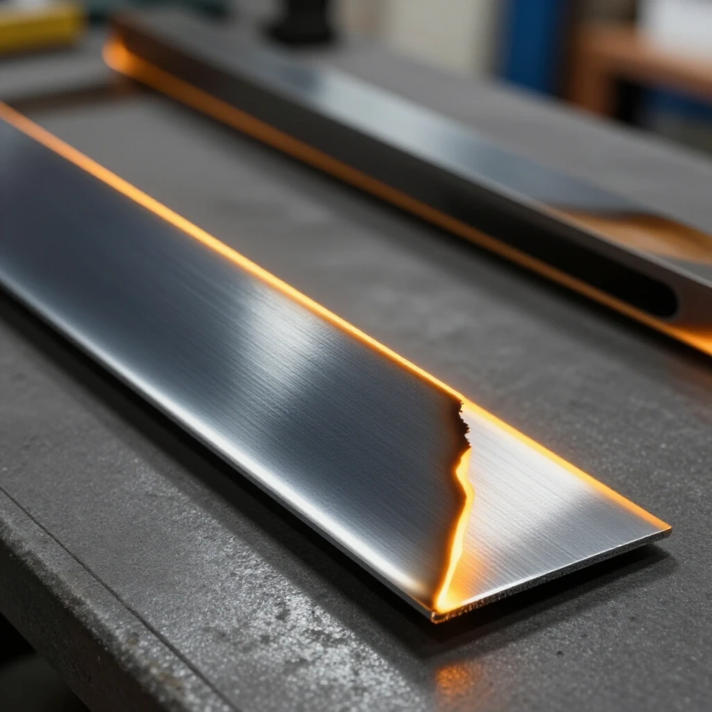
When you strike an arc, the steel in the immediate area reaches a molten state, while the surrounding metal remains relatively cool. This temperature differential is the root cause of almost every structural alignment fault I’ve encountered. As the weld pool cools, it shrinks. If the parts are not restrained, the shrinking weld bead acts like a powerful spring, pulling the base metal toward the center of the joint.
I often tell my apprentices to think of a weld as a cooling rubber band. If you stretch a rubber band between two points and let it go, it pulls those points together. In fabrication, we use mechanical restraints to fight that “pull.” Understanding the magnitude of this force is the first step in any metalworking diagnostic guide. For mild steel, the contraction can be significant enough to bend 1/4-inch plate if your clamping strategy is weak or poorly placed.
Common Types of Weld-Induced Distortion
- Angular Distortion: This occurs when the weld pulls the two pieces of metal toward each other at an angle, usually seen in fillet or V-groove welds.
- Longitudinal Bowing: This happens when a long weld bead shrinks along its length, causing the entire workpiece to curve like a bow.
- Transverse Shrinkage: This is the contraction of the metal perpendicular to the weld line, which can reduce the overall width of your assembly.
- Buckling: Often seen in thinner sheets (under 1/8 inch), where the internal stresses cause the metal to “oil-can” or wave.
Establishing a Diagnostic Baseline for Shop Fixturing
A diagnostic baseline is a set of known measurements and conditions used to identify where a fabrication process is failing. Before you even turn on the welder, you must verify that your starting point is true and that your tools are calibrated.
I’ve seen many fabricators blame their welding technique for a warped frame when the real culprit was a non-planar welding table. If your table has a 1/16-inch dip in the center, your finished part will reflect that error. I start every complex project by checking my work surface with a precision straightedge and a digital level. If the table isn’t flat, no amount of clamping will result in a square part.
Building a baseline also involves checking your material. Mill-scale and slight factory bows are common in hot-rolled mild steel. I use a digital dial indicator to check for straightness over a four-foot span. If I find a deviation of more than 0.020 inches, I know I need to account for that pre-existing stress before I start my layout. This is the foundation of mechanical troubleshooting steps: eliminate the “known-goods” so you can focus on the variables you create during the process.
Baseline Calibration Checklist
- Table Planarity: Verify the welding surface is flat within 0.010 inches across the working area.
- Square Verification: Check all squares and 90-degree magnets against a known reference block.
- Material Inspection: Measure stock for factory twists or “camber” using a string line or straightedge.
- Clamp Condition: Inspect C-clamps and F-clamps for stripped threads or bent frames that might lose tension under heat.
Mechanical Restraint Techniques for Small Shop Projects
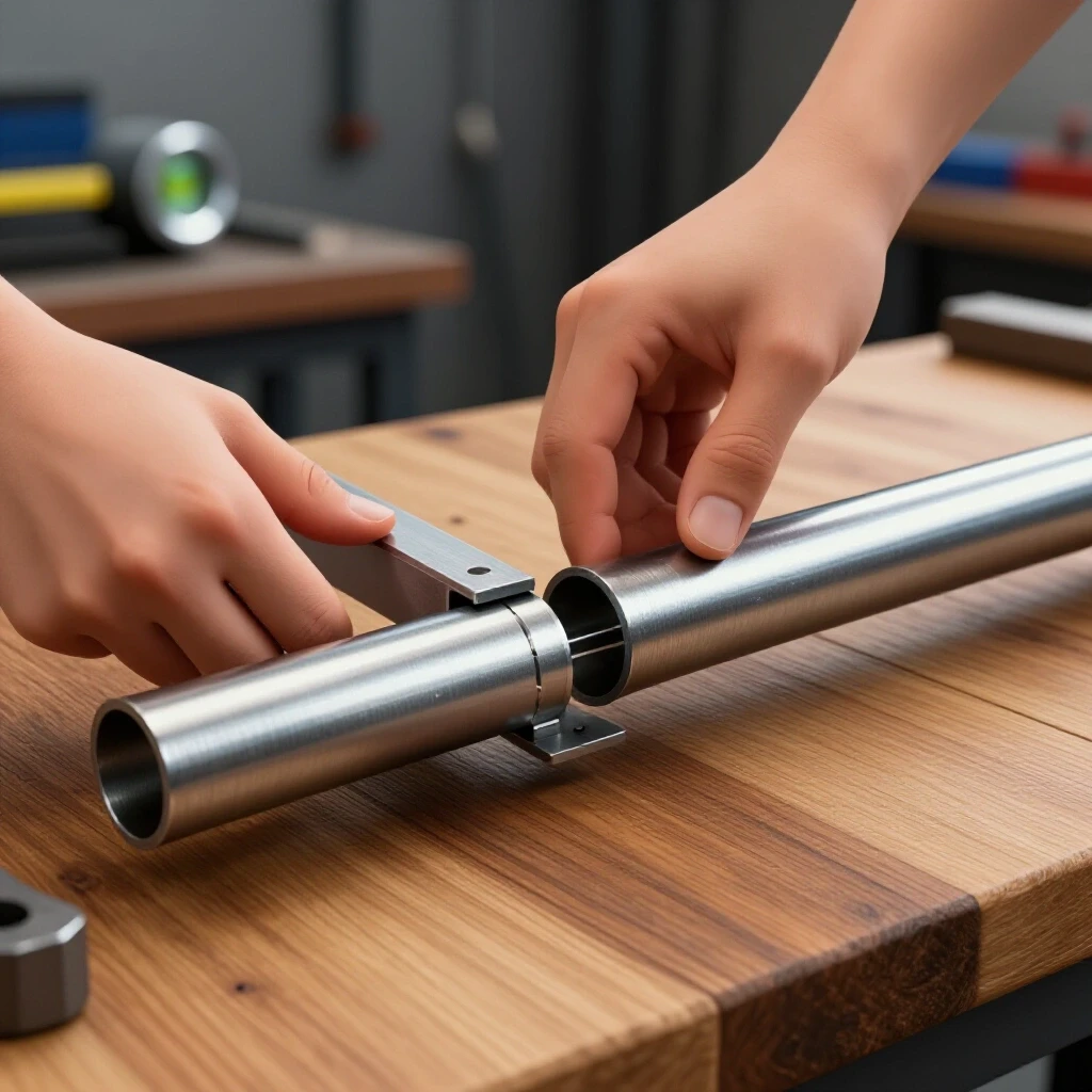
Mechanical restraint involves using external force to keep steel components in alignment during the welding process. The goal is to provide enough counter-force to resist the shrinkage of the cooling weld pool.
In my experience, the most effective restraint is a combination of heavy-duty clamps and “dogs” or wedges. For mild steel up to 1/4 inch, I prefer using F-style sliding clamps because they allow for quick adjustments while providing up to 1,000 pounds of clamping force. However, simply tightening a clamp is not enough. You must place the clamp as close to the joint as possible without it interfering with the torch or electrode.
Interestingly, over-clamping can sometimes be as detrimental as under-clamping. If you restrain a piece so tightly that it cannot move at all, the internal stresses have nowhere to go. This can lead to cracking in the weld bead or the heat-affected zone (HAZ). I look for a “firm-but-not-crushed” tension. A good rule of thumb is to tighten the clamp until the material is seated against the table, then add another half-turn.
Comparison of Clamping Forces and Material Thickness
| Material Thickness | Recommended Clamp Type | Typical Clamping Force | Target Tolerance |
|---|---|---|---|
| 16 Gauge (0.060″) | Spring Clamps / Clecos | 50-100 lbs | +/- 0.015″ |
| 1/8 inch (0.125″) | Light F-Clamps | 300-500 lbs | +/- 0.030″ |
| 3/16 inch (0.187″) | Medium C-Clamps | 600-800 lbs | +/- 0.045″ |
| 1/4 inch (0.250″) | Heavy Duty F-Clamps | 1,000+ lbs | +/- 0.060″ |
Using Strongbacks and Backing Bars to Control Bowing
Strongbacks are temporary stiffeners welded across a joint to prevent the base metal from pulling out of plane. They are essentially the “internal skeleton” of your fixturing strategy.
When I’m working on a long butt weld on 1/4-inch plate, I know that longitudinal bowing is my biggest enemy. To combat this, I tack-weld pieces of heavy angle iron or scrap C-channel across the seam on the side opposite the weld. These “strongbacks” provide the rigidity the flat plate lacks. Once the weld is complete and the metal has cooled to room temperature, I carefully grind off the tacks and remove the stiffeners.
Backing bars serve a dual purpose. They act as a heat sink to draw thermal energy away from the joint, and they provide a physical stop to prevent the plates from pulling together. For DIY setups, a thick piece of copper bar is an excellent backing material because the steel weld won’t stick to it. If you don’t have copper, a thick piece of scrap steel works, though you must be careful not to accidentally weld your project to the backing bar.
Steps for Implementing Strongbacks
- Select Material: Use a stiff section like 2x2x1/4 angle iron that is at least 50% thicker than the workpiece.
- Positioning: Place the strongback every 6 to 8 inches across the seam.
- Tacking: Use small, 1/2-inch tacks at the ends of the strongback.
- Cooling: Do not remove the strongback until the workpiece is cool to the touch (below 100°F).
Systematic Tack Welding and Sequencing
Tacking is the process of using small, temporary welds to hold parts in place before the final pass. A well-planned tacking sequence is the “software” that runs your “hardware” (the clamps).
I’ve seen many talented welders fail because they started at one end of a joint and welded all the way to the other. This “zipper effect” pushes heat in one direction, causing the gap to close or open as you go. Instead, I use a “center-out” or “staggered” tacking sequence. By placing tacks at the ends, then the middle, then bisecting those distances, I distribute the heat more evenly across the entire structure.
For a standard 24-inch joint, I start with 1/2-inch tacks at both ends. Then I place one in the dead center. From there, I fill in the gaps. This prevents the metal from “walking” or shifting during the final weld. If you notice the gap closing as you tack, you can use a flat-head screwdriver or a wedge to maintain the spacing. This is a critical part of troubleshooting weld porosity and alignment; if the gap is inconsistent, your gas coverage and penetration will be too.
Tack Welding Best Practices
- Size Matters: Tacks should be about 3 to 4 times the thickness of the metal in length.
- Penetration: Ensure the tack has good fusion; a “cold” tack will snap under the stress of the main weld.
- Spacing: On 1/8-inch to 1/4-inch steel, space tacks every 3 to 4 inches.
- Cleaning: Always grind the start and stop of your tacks before the final pass to avoid inclusions.
Troubleshooting Common Fabrication Errors
Troubleshooting involves identifying the root cause of defects like porosity or misalignment through a process of elimination. When a part warps despite your best efforts, you have to look at the data.
Was the heat too high? Did the clamps slip? Was the sequence wrong? I recently worked on a project where a series of motor mounts were consistently pulling 5 degrees out of square. After a systematic review, I found that the welder was using a travel speed that was too slow. This dumped excessive heat into the joint, overcoming the resistance of the clamps. By increasing the wire feed speed and moving faster, we reduced the heat-affected zone and solved the distortion issue.
Another common issue is “magnetic arc blow,” which can feel like a mechanical alignment problem but is actually electrical. If your ground clamp is poorly placed, the magnetic field can pull the arc to one side, causing uneven heating and lopsided distortion. I always place my ground as close to the weld zone as possible to ensure a stable arc. This is part of the metalworking diagnostic guide: look at the electricity, the heat, and the mechanics simultaneously.
Troubleshooting Table: Distortion vs. Porosity vs. Alignment
| Symptom | Potential Root Cause | Diagnostic Test | Recommended Fix |
|---|---|---|---|
| Angular Pull | Excessive heat in the root | Measure leg length of weld | Reduce voltage; increase travel speed |
| Longitudinal Bow | Long, continuous weld beads | Check for “banana” shape with string | Use back-step welding technique |
| Surface Porosity | Shielding gas turbulence | Check flow meter and nozzle | Set flow to 20-25 CFH; clean nozzle |
| Misalignment | Table or fixture flex | Use dial indicator on fixture | Reinforce table; use heavier clamps |
| Tool Chatter | Lack of rigidity in setup | Hand-test for vibration | Shorten tool overhang; tighten gibs |
The Role of Heat Sinks and Chill Bars
A heat sink is a mass of material placed near the weld to absorb and dissipate thermal energy. In the world of mechanical troubleshooting steps, managing heat is just as important as managing force.
If I am welding a thin 1/8-inch plate to a heavy 1/2-inch frame, the thin plate is going to soak up all that heat and distort instantly. To prevent this, I clamp a large “chill bar”—usually a thick piece of scrap steel or aluminum—right next to the weld path on the thin plate. The chill bar acts like a sponge, pulling the excess heat away before it can cause the thin metal to reach its expansion limit.
Aluminum is a fantastic material for chill bars because its thermal conductivity is much higher than steel’s. However, be careful not to get the aluminum too close to the arc, or you might contaminate your weld. I find that a 1-inch thick aluminum bar clamped 1/2 inch away from the seam is the “sweet spot” for most DIY mild steel projects.
Advanced Diagnostic Tools for the Modern Shop
While a square and a clamp are essential, modern tools can help you identify issues that are invisible to the naked eye. Digital technology has made it much easier to track down “electrical gremlins” or subtle mechanical shifts.
- Infrared Thermometers: I use an IR temp gun to monitor the interpass temperature. If the steel exceeds 500°F, I stop and let it cool. Excessive heat is the primary driver of distortion.
- Digital Dial Indicators: These are invaluable for checking if a part is moving during the welding process. I sometimes rig one up on a magnetic base away from the heat to see how many thousandths of an inch the metal pulls as it cools.
- Smartphone Vibration Analyzers: If you are experiencing tool chatter or machinery vibration, there are apps that use your phone’s accelerometer to map frequency. This helps you identify if the vibration is coming from a loose motor mount or a spindle bearing.
- Digital Protractor: For checking angular distortion, a digital protractor is much more accurate than a manual one, allowing you to see shifts as small as 0.1 degrees.
Case Study: Isolating Tool Chatter in a Lathe Setup
I once worked with a fabricator who was struggling with terrible surface finish on a lathe. He thought it was a material issue, but it turned out to be a classic “tool chatter” problem rooted in poor clamping and rigidity.
We started by checking the spindle backlash. We found 0.005 inches of play, which was within tolerance but not ideal. Next, we looked at the tool post. By using a digital dial indicator, we saw that the tool was deflecting 0.010 inches under load. The “fix” wasn’t a new tool; it was shortening the tool overhang and tightening the carriage gibs.
This relates directly to welding distortion because both issues stem from a lack of rigidity. Whether it’s a lathe tool vibrating at a high frequency or a steel plate bowing under thermal stress, the diagnostic path is the same: isolate the moving part, measure the deflection, and increase the restraint. Once we stiffened the setup, the chatter disappeared, and the surface finish became mirror-like.
Final Assembly and Inspection Benchmarks
Once the welding is done, the diagnostic process isn’t over. You need to verify that your finished product meets the required tolerances. In my shop, I have a “Zero-Point” inspection I perform on every structural project.
I wait until the part is completely cool—not just “warm,” but room temperature. Metal continues to move until it has fully equalized. I then use a combination of a 48-inch precision level and a set of feeler gauges. If I can’t slide a 0.015-inch feeler gauge under the part at any point on the table, I consider it a success.
If the part is out of spec, I don’t reach for the torch to “heat-straighten” it immediately. First, I document where it went wrong. Did it pull toward the side with the most welds? Did the clamps slip? Keeping a repair log or a fabrication journal is the best way to ensure you don’t make the same mistake on the next project. This data-driven approach is what separates a “parts changer” from a true diagnostic specialist.
Final Inspection Benchmarks
- Flatness: Less than 0.030 inches of deviation over a 4-foot span for general fabrication.
- Squareness: Within 0.060 inches (1/16″) over 2 feet for frames and mounts.
- Weld Quality: No visible porosity, undercut less than 1/32 inch, and full fusion at the toes.
- Dimensions: Overall length/width within 1/32 inch of the design plan.
By following these systematic steps—from establishing a baseline to using strategic restraints and monitoring heat—you can significantly reduce the “guesswork” in your shop. Metalworking is a game of managing forces. When you understand those forces, you stop fighting the metal and start commanding it.
Frequently Asked Questions
Why does my steel always pull toward the weld, even when I use heavy clamps? This happens because the cooling weld bead is physically shrinking. When steel transitions from a liquid to a solid and then cools to room temperature, its volume decreases. This “shrinkage force” is incredibly strong. If your clamps are only holding the edges of the plate, the center of the plate can still bow. You need to use stiffeners like strongbacks or increase the number of tacks to distribute that force across a larger area.
How many tacks do I really need for a 1/4-inch steel frame? For 1/4-inch material, a good rule of thumb is a 1/2-inch long tack every 4 to 6 inches. However, the sequence is more important than the number. Always tack the corners first, then the centers, and work your way in. This traps the metal in a “grid” of tacks, preventing it from shifting in one direction as you apply the final beads.
Can I use wood or plastic clamps for welding? No. Wood and plastic clamps cannot provide the necessary clamping force (often 500-1,000 lbs) required to resist thermal distortion. Furthermore, the heat from the welding process will melt or char them, leading to a loss of tension mid-weld. Stick to forged steel C-clamps or heavy-duty F-clamps designed for metalworking.
What is the best way to prevent “oil-can” buckling in thin sheet metal? Buckling in thin sheets (under 1/8 inch) is caused by the expansion of the heated metal being trapped by the cooler surrounding metal. The best way to prevent this is to use “back-step” welding. Instead of one long bead, weld in short 1-inch segments, moving in the opposite direction of the overall travel. This keeps the heat localized and allows it to dissipate more evenly.
Does the type of welding (MIG vs. Stick) change how I should clamp? The physics of expansion remains the same, but the heat input varies. MIG (GMAW) typically has a more concentrated heat zone, while Stick (SMAW) often puts more total heat into the part due to slower travel speeds. If you are stick welding, you generally need more robust clamping and longer cooling times between passes because the total thermal load on the steel is higher.
How do I know if I’m over-clamping my project? You are over-clamping if you see the weld bead cracking as it cools or if the metal starts to deform around the clamp pads. Mild steel needs a tiny bit of “breathing room” to handle internal stresses. If a weld snaps or “pings” shortly after you finish, it’s a sign that the restraint was so rigid that the metal had to crack to relieve the stress.
Should I leave a gap between my plates (root opening), or should they be touching? For 1/8-inch and thicker mild steel, a small root opening (about 1/16 to 3/32 inch) is usually recommended for full penetration. However, this gap makes the part more prone to “transverse shrinkage” (pulling together). To combat this, use tacks or spacers (like a piece of welding wire) to maintain the gap, and keep your clamps tight until the joint is fully welded and cooled.
How long should I wait before removing the clamps? Patience is the most underused tool in the shop. You should wait until the metal is “hand-warm,” which is generally below 100°F. If you remove the clamps while the steel is still at 300°F or 400°F, it is still in a weakened state and will likely warp the moment the mechanical restraint is gone. Use an infrared thermometer to verify the temperature if you want to be precise.
What is “back-step” welding and how does it help with clamping? Back-stepping is a technique where you start a weld an inch or two ahead of the previous segment and weld back toward it. This helps because each new segment is pulling against a weld that has already started to solidify and provide its own restraint. It works in tandem with your clamps to keep the longitudinal bowing to a minimum.
My welding table is cast iron. Can I weld strongbacks directly to it? No. You should never weld directly to a cast iron table, as the heat will cause the cast iron to crack (due to its high carbon content and low ductility). Instead, use the holes in the table (if it’s a fixture table) or use heavy-duty clamps to secure your strongbacks and workpieces to the surface. If you have a steel-top table, you can tack to it, but you’ll have to grind the table smooth afterward.
(This article was written by one of our staff writers, Paul Whitaker. Visit our Meet the Team page to learn more about the author and their expertise.)