Pure Argon vs Argon CO2 Mix Shielding Gas for MIG (Review)
I remember a Tuesday morning three years ago when a long-time client called me to his shop. He was working on a series of structural frames for a heavy equipment manufacturer. Every weld looked like a row of grapes—lumpy, cold, and barely holding on. He had checked his wire speed, his voltage, and his ground clamp. He was frustrated because his machine settings were exactly where they had been the day before, yet the results were disastrous. After ten minutes of looking at the arc, I realized someone had swapped his 75/25 argon-CO2 mix for a cylinder of straight argon. It was a simple mistake that highlighted a fundamental truth in fabrication: the gas you choose dictates the physics of the arc.
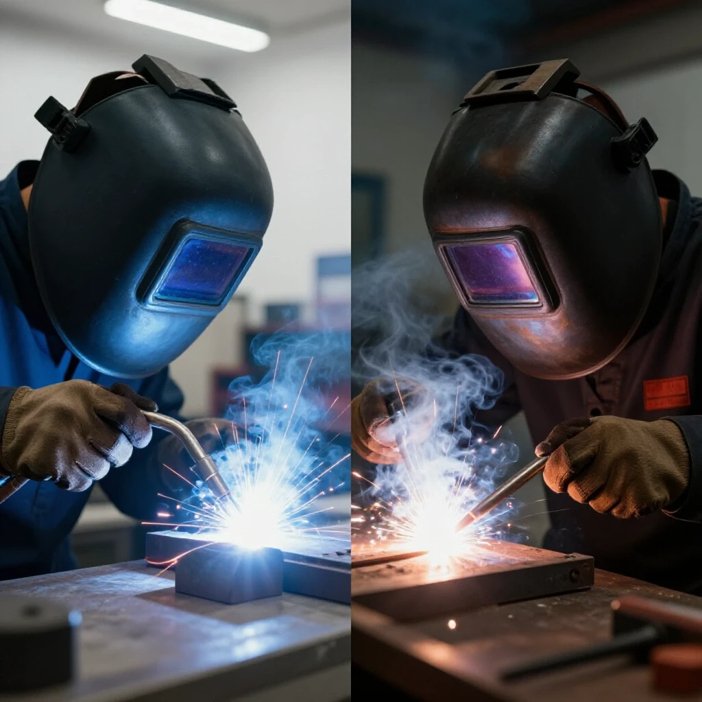
Mastering the diagnostic process in a workshop requires more than just turning dials. It requires an understanding of how different shielding environments interact with the metal. When you are troubleshooting poor weld quality or unexpected machine behavior, you have to look at the variables one by one. This guide focuses on the systematic evaluation of pure inert gases versus active gas blends in MIG welding. We will look at how these choices affect penetration, spatter, and the overall stability of your fabrication process.
Systematically Isolating Shielding Gas Variables
Isolating variables is the first step in any diagnostic framework. You must separate the gas delivery from mechanical issues like wire feed tension or electrical problems like a failing contact tip. This involves verifying the flow rate, checking for leaks in the lead, and ensuring the gas type matches the metallurgical needs of the workpiece.
When a weld starts failing, I always start at the bottle and work toward the torch. If you are using a 100% argon gas on mild steel, you will notice the arc is unstable and the bead is narrow with high reinforcement. This happens because argon is an inert gas. It doesn’t react with the puddle. On the other hand, adding a small amount of CO2 makes the gas “active.” This activity changes the surface tension of the molten metal.
To troubleshoot effectively, you should use a flow meter at the nozzle, not just the regulator at the tank. A reading of 20 to 25 cubic feet per hour (CFH) at the tank doesn’t mean you have that much at the arc if your liner is leaking. I use a portable pea-style flow meter to verify actual delivery. If the flow is consistent but the arc is still “wandering,” the chemistry of the gas is usually the culprit.
Why Pure Argon Behaves Differently on Ferrous Metals
Argon is a noble gas with a low ionization potential, meaning it turns into a plasma quite easily. However, when used alone on mild steel, it creates a very narrow heat profile. The center of the arc is hot, but the edges stay cool, leading to a “pencil-point” penetration pattern that often results in lack of fusion at the toes of the weld.
In my experience, using straight argon on steel is a recipe for structural alignment faults. Because the heat is so concentrated, the weld doesn’t “wet out” or flow into the base metal. This creates a high, ropey bead. If you are trying to align heavy plates, this lack of side-wall fusion can cause the joint to fail under stress. I once saw a heavy-duty bracket snap clean off because the fabricator used pure argon on 1/2-inch plate. The weld looked okay on top, but it had zero penetration into the corners.
If you are seeing a “tunneling” effect where the weld sits on top of the metal like a bead of caulk, you are likely using the wrong gas for the material. On the flip side, pure argon is the standard for non-ferrous metals like aluminum. The diagnostic challenge is knowing when the gas is the tool and when it is the problem.
The Role of CO2 in Stabilizing the MIG Arc
Adding CO2 to an argon base creates a mixture that is more thermally conductive. This means the heat is distributed more evenly across the arc, resulting in a wider, flatter weld bead. The CO2 also helps to clean the surface of the metal by reacting with the molten puddle, which can reduce certain types of surface porosity.
Most industrial shops rely on a 75% Argon / 25% CO2 or an 85% Argon / 15% CO2 blend for general steel fabrication. The CO2 provides the “punch” needed for deep penetration. However, higher levels of CO2 also increase spatter. If you are troubleshooting excessive cleanup time, your gas mix might have too much CO2 for the voltage you are running.
When I evaluate a shop’s workflow, I look at the “spatter map” around the weld. If the spatter consists of large, spherical balls, the voltage is likely too low for the gas mix. If the spatter is fine and dusty, the voltage might be too high. Finding the “sweet spot” involves balancing the gas activity with the machine’s electrical output.
| Feature | 100% Argon | Argon / CO2 Mix (75/25) |
|---|---|---|
| Material | Aluminum, Titanium, Copper | Mild Steel, Low Alloy Steel |
| Arc Stability | Very High (on non-ferrous) | High (on ferrous) |
| Penetration Profile | Deep center, shallow edges | Broad, deep, and consistent |
| Spatter Level | Virtually Zero | Moderate to Low |
| Transfer Mode | Spray (at high volts) | Short-circuit, Globular, or Spray |
| Wetting Action | Poor on steel | Excellent on steel |
Troubleshooting Weld Porosity and Arc Instability
Weld porosity is the presence of tiny holes or “bubbles” trapped in the weld metal, often caused by the loss of shielding gas coverage. When troubleshooting porosity, you must determine if the issue is a lack of gas, contaminated gas, or the wrong gas for the application.
I once spent four hours diagnosing a porosity issue on a robotic welding cell. We checked the gas lines, replaced the diffuser, and even swapped the wire spool. It turned out to be a “venturi effect” where a small tear in the gas hose was actually sucking air into the line rather than leaking gas out. This air contamination ruined every weld.
To diagnose this, I use a systematic “pressure drop” test. 1. Close the cylinder valve. 2. Observe the high-pressure gauge. 3. If the needle drops more than 5 PSI in 10 minutes, you have a leak. 4. Use a soapy water solution to find the bubble—don’t forget to check the internal solenoid inside the welder.
If the gas delivery is perfect but you still have porosity, look at the material. Pure argon on oily or mill-scaled steel will almost always result in porosity because it lacks the “cleaning action” of an active gas mix.
Evaluating Penetration Profiles and Bead Morphology
Bead morphology refers to the shape and size of the weld bead. By looking at the cross-section of a weld, you can diagnose whether your gas selection is providing enough heat to the root of the joint. Pure argon creates a “finger” of penetration that is very narrow, while CO2 blends create a wider “U-shaped” profile.
In structural fabrication, the goal is often a 1-to-1 ratio of width to depth. If your bead is 0.500 inches wide but only 0.050 inches deep, you have a serious penetration issue. This often happens when fabricators try to use pure argon to “keep things clean” on steel. They get a pretty weld, but it lacks the structural integrity required for heavy loads.
I use a simple “macro-etch” test when I suspect gas issues. I cut a sample weld, polish the cross-section with 400-grit sandpaper, and apply a mild acid. This reveals the penetration profile. If I see that “finger” shape on a steel joint, I know we need to move to a gas with at least 10% to 25% CO2 to broaden that heat zone.
Impact of Gas Selection on Machine Harmonics and Duty Cycle
The choice of shielding gas directly affects the electrical resistance of the arc, which in turn impacts the machine’s power supply. Pure argon has lower resistance than CO2. This means that for the same wire speed, you will need different voltage settings depending on the gas you use.
If you hear a “harsh” or “growling” sound from your transformer or inverter, it might be struggling with arc instability. This is often seen when trying to run a high-CO2 mix at low voltages. The machine enters a “globular transfer” mode where large drops of metal short out the arc, causing massive current spikes. These spikes can lead to tool chatter in nearby CNC equipment or even trip sensitive breakers.
- Short-Circuit Transfer: Usually requires 17–22 Volts. Best with 75/25 Argon/CO2.
- Spray Transfer: Usually requires 25+ Volts. Requires at least 80% Argon.
- Globular Transfer: The “no-man’s land” between the two. Causes high vibration and spatter.
When a machine is vibrating excessively or the arc feels “stiff,” I check the voltage-to-gas ratio. A common mistake is trying to run spray transfer with too much CO2. You can’t reach a true spray transfer if your CO2 content is above 20% to 25%; the arc will simply stay in a violent globular state.
Diagnostic Framework for Transitioning Between Gas Blends
When a shop decides to switch from one gas to another, they often forget to recalibrate their machines. This leads to a week of “mystery” defects. I recommend a formal transition checklist to ensure the mechanical and metallurgical variables remain under control.
- Check the Liner: If you’ve been running a lot of CO2, your liner might be full of “fines” or dust from the wire. Pure argon processes are more sensitive to wire feed consistency.
- Verify Voltage Offsets: Moving from 75/25 to 90/10 Argon/CO2 usually requires dropping your voltage by 1 to 2 volts to maintain the same arc length.
- Inspect the Contact Tip: High-argon mixes run hotter at the tip. If you are experiencing “burn-back” (where the wire welds itself to the tip), you may need to increase your wire speed or use a heavy-duty tip.
- Test for “Arc Blow”: Pure argon arcs are more easily deflected by magnetic fields. If the arc is pulling to one side, check your ground placement.
Real-World Case Study: Resolving Structural Alignment Faults
A millwright I know was struggling with a large gearbox housing. Every time he welded the support ribs, the housing warped by more than 0.030 inches, which was outside the tolerance for the bearing alignment. He was using a high-CO2 mix, which was putting too much total heat into the part.
We switched him to a 92% Argon / 8% CO2 blend. This allowed him to move into a “spray transfer” mode. In spray transfer, the metal is delivered in tiny droplets, allowing for faster travel speeds. By moving faster, he reduced the total heat input (Joules per inch) into the housing.
The result? The warping dropped to 0.008 inches, well within the allowable limit. This case proves that gas selection isn’t just about the weld bead; it’s about the mechanical stability of the entire assembly. By choosing a gas that allowed for a more efficient transfer of metal, we solved a structural alignment problem that had nothing to do with the “strength” of the gas itself.
Actionable Tracking Framework for Gas Performance
To stop the guesswork, I suggest keeping a “Weld Parameter Log.” This is especially helpful when you have multiple operators or shifts. If a machine starts acting up, you can compare the current state to a known “good” state.
- Baseline Date: When the machine was last performing perfectly.
- Gas Composition: Verified by the label on the cylinder.
- Flow Rate: Measured at the nozzle (e.g., 22 CFH).
- Voltage/WFS: The specific settings for a given material thickness.
- Visual Notes: Describe the arc (e.g., “Soft hiss,” “Crisp crackle,” or “Violent pop”).
If the “Visual Notes” change from a “hiss” to a “pop” and the settings haven’t moved, you likely have a gas contamination issue or a change in gas composition. This systematic approach saves hours of frustration.
Conclusion
Troubleshooting fabrication issues is a process of elimination. When you understand how different shielding environments change the arc, you stop being a “dial-turner” and start being a diagnostic specialist. Whether you are dealing with porosity, poor penetration, or machine vibrations, always look at the gas as a primary variable. It is the medium through which all your electrical energy passes. If the medium is wrong, the result can never be right. By keeping your flow rates consistent, matching your gas to your metal, and monitoring your penetration profiles, you can resolve even the most stubborn workshop gremlins.
FAQ
Why does my MIG welder produce a lot of spatter when I use pure argon on steel? Pure argon is not recommended for MIG welding on mild steel. It creates an unstable arc because it lacks the active components (like CO2 or Oxygen) needed to stabilize the plasma on ferrous metals. This instability causes the wire to “pop” and “short out” inconsistently, leading to heavy spatter and poor bead shape.
Can I use a 75/25 Argon/CO2 mix for welding aluminum? No. The CO2 in the mix will react with the molten aluminum, causing heavy oxidation and extreme porosity. Aluminum requires a 100% inert environment, which is why pure argon (or an argon/helium mix) is the only choice for MIG welding aluminum.
How does gas flow rate affect weld porosity? If the flow rate is too low (below 15 CFH), the wind or even slight drafts can blow the shield away, letting air into the weld. If the flow rate is too high (above 40-50 CFH), it can create “turbulence.” This turbulence actually sucks air into the gas stream, which causes porosity just as easily as having no gas at all.
What is the “Spray Transfer” mode and which gas do I need for it? Spray transfer is a high-energy welding mode where the wire melts into tiny droplets before touching the puddle. It is very fast and produces almost no spatter. To achieve this, you generally need a gas mix with at least 80% argon and a voltage setting above 24-25 volts.
Why is my weld bead so “tall” and narrow? A tall, narrow bead (high reinforcement) is often a sign of using too much argon on steel or having the voltage set too low. The metal isn’t “wetting out” or spreading. Adding more CO2 to your gas mix or increasing your voltage will help flatten the bead and improve side-wall fusion.
Does shielding gas affect the “sound” of the weld? Yes. A 75/25 mix usually produces a “bacon frying” crackle, which is characteristic of the short-circuit transfer mode. High-argon mixes (90%+) used at high voltages will produce a “hissing” sound, indicating a spray transfer. If the sound is irregular or “stuttering,” it usually indicates a gas flow or contamination issue.
How can I tell if my gas cylinder is contaminated? If you have ruled out leaks, checked your flow rate, and cleaned your material, but you still have “pepper” (tiny black dots) or bubbles in your weld, the gas itself may be contaminated with moisture or air. The only way to verify this is to swap the cylinder for a known “good” one and see if the problem disappears.
What is the best gas for welding thin-gauge sheet metal? For thin steel, a 75% Argon / 25% CO2 mix is usually best. The CO2 helps stabilize the arc at low voltages, which is necessary to prevent burning through the thin material. Pure argon would likely cause the arc to wander and make it difficult to maintain a consistent puddle.
Can gas selection cause machine vibrations? Indirectly, yes. If the gas mix is wrong for the voltage, the arc becomes unstable. This creates rapid, violent fluctuations in current (amperage). These fluctuations can cause the wire drive motor to “chatter” and put stress on the machine’s internal electronics, leading to felt vibrations in the torch or the machine cabinet.
What should I check if I have porosity only at the start of a weld? This is often caused by a “gas surge.” When the solenoid opens, a burst of high-pressure gas hits the weld, creating turbulence. You can solve this by using a gas surge protector or by shortening the gas hose between the regulator and the welder to reduce the volume of trapped, pressurized gas.
(This article was written by one of our staff writers, Paul Whitaker. Visit our Meet the Team page to learn more about the author and their expertise.)