How to Weld Thick Structural Steel Plates Safely (Tutorial)
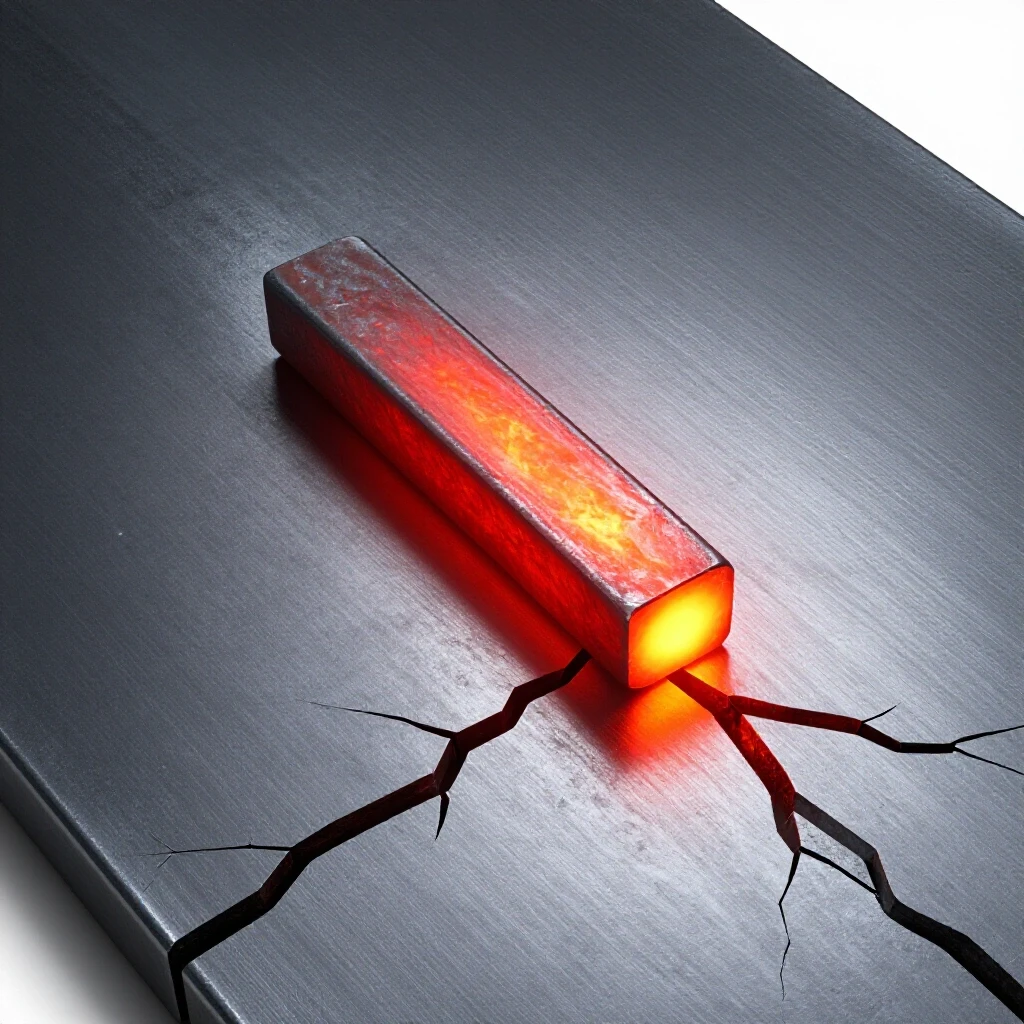
I remember standing over a 30-millimeter-thick base plate five years ago, staring at a transverse crack that had just zipped through my third filler pass. The sound it made was like a pistol shot echoing in the shop. I had followed the basic settings on the machine door, but the weld failed anyway. That moment taught me that when you move into heavy-section fabrication, the margin for error disappears. You can no longer rely on “feel” or general settings; you need a systematic diagnostic approach to manage the heat, the chemistry, and the mechanical stresses involved.
In my 18 years of troubleshooting industrial setups, I have found that most failures in heavy plate joining come from a lack of variable control. Whether it is a wandering arc caused by magnetic interference or hydrogen cracking from improper thermal management, the solution is always found through isolation. We have to treat the welding environment like a laboratory. If a weld is porous or a machine is surging, we don’t just turn knobs randomly. We test the gas, then the wire, then the electrical path, until the outlier reveals itself.
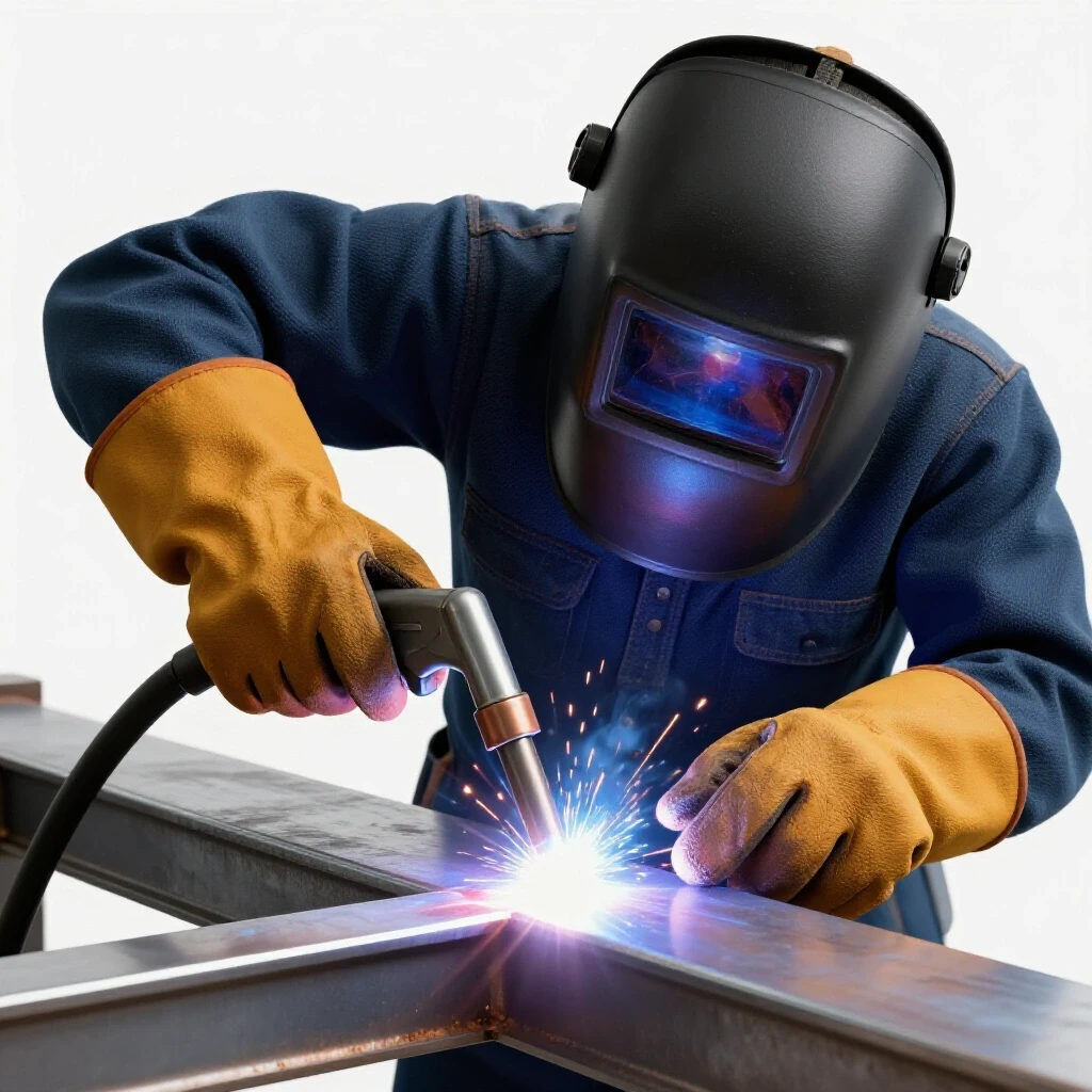
This guide is built for those of you who are tired of “guessing” why a heavy joint failed or why your machine is acting up. We are going to look at the mechanics of joining steel 25 mm and thicker. We will break down how to prepare the metal, manage the heat, and troubleshoot the equipment that makes it all possible. My goal is to give you the diagnostic tools to look at a defect and know exactly which variable in your process caused it.
Establishing a Diagnostic Framework for Heavy Section Joining
A diagnostic framework is a structured method of elimination used to identify the root cause of a fabrication failure or machine malfunction. It moves from the most obvious external factors to the complex internal variables.
When I approach a heavy-plate project, I start by mapping the process. If I encounter an issue like unexpected porosity, I don’t just replace the gas bottle. I use a “Fault Tree” approach. I check the nozzle for spatter, then the gas flow rate at the torch, then the integrity of the lead connections, and finally the base metal cleanliness. By isolating each component, I avoid the frustration of changing five things at once and never knowing which one actually fixed the problem.
In heavy fabrication, the variables are magnified. A small amount of moisture on a 5 mm plate might just cause a bit of spatter. On a 30 mm plate, that same moisture can lead to under-bead cracking that ruins the entire assembly. We must establish a baseline for our equipment and materials before the first arc is struck. This means verifying that our power source is delivering consistent voltage and that our base metal is at the correct temperature.
Initial System Observation and Isolation Steps
Systematic observation involves recording the machine’s behavior and the weld’s appearance under specific conditions to identify patterns. This step prevents “parts-swapping” and focuses on data-driven repairs.
- Document the Baseline: Record your voltage, wire feed speed (WFS), and gas flow rate. If the arc sounds “crispy” but the weld looks cold, your voltage drop across the leads might be too high.
- Isolate the Power Path: Check all ground clamps and lead connections. On heavy sections, a loose ground can cause erratic arc behavior that mimics a faulty wire feeder.
- Verify Material Conditions: Use a digital hygrometer to check shop humidity and an infrared thermometer to verify the steel temperature. Thick steel acts as a massive heat sink, pulling moisture from the air if it is colder than the dew point.
Mechanical Preparation and Joint Geometry Diagnostics
Joint geometry refers to the specific shape and angles ground into the edges of the steel plates to ensure full penetration of the weld metal. Proper geometry reduces the amount of filler metal needed and minimizes internal stress.
If your bevel angle is too narrow, you will struggle with “sidewall lack of fusion,” where the weld doesn’t stick to the sides of the groove. If the root opening is too wide, you will blow through the bottom. For steel over 25 mm, I typically look for a 60-degree included angle (30 degrees on each plate). This provides enough room for the welding nozzle to reach the bottom while keeping the total weld volume manageable.
I once spent two days troubleshooting “inter-run inclusions” on a heavy bridge bracket. It turned out the fabricator was using a 20-degree bevel to save on wire. The arc couldn’t reach the corners of the groove, leaving pockets of slag behind. Once we opened the bevel to 30 degrees per side, the defects vanished. Geometry is the foundation of a sound heavy-section weld.
Measuring and Verifying Joint Tolerances
Precise measurements ensure that the weld bead can properly fuse with the base metal without creating areas of high stress or trapped slag. These metrics are the difference between a repairable error and a total scrap.
- Bevel Angle: Use a dedicated protractor or bevel gauge. Aim for 30 to 35 degrees per side for a single-V groove.
- Root Face (Land): This is the flat spot at the bottom of the bevel. For heavy plate, a 2 mm to 3 mm land helps support the heat of the first pass.
- Root Opening (Gap): Use a 3 mm or 4 mm spacer to ensure the gap is consistent across the entire length of the joint. Consistent gaps prevent the “pulling” that leads to misalignment.
| Feature | Target Measurement | Diagnostic Sign of Failure |
|---|---|---|
| Bevel Angle | 30° – 35° (per side) | Lack of sidewall fusion; slag traps |
| Root Opening | 3.0 mm – 4.0 mm | Lack of penetration; excessive burn-through |
| Root Face | 1.6 mm – 3.2 mm | Root cracking; melt-through |
| Fit-up Alignment | Within 1.5 mm | High-low stress concentrations; uneven loading |
Thermal Dynamics: Managing Preheat and Interpass Temperatures
Thermal management is the practice of heating the base metal before and during the welding process to slow the cooling rate of the weld pool. This is critical for preventing the formation of brittle microstructures in thick steel.
Thick steel plates are excellent conductors of heat. When you strike an arc, the surrounding cold metal sucks the heat away instantly. This rapid cooling can trap hydrogen in the weld, leading to “cold cracking” hours after the job is finished. To prevent this, we use preheating. For a 25 mm mild steel plate, a preheat of 100°C to 150°C is often the baseline.
Interpass temperature is just as important. This is the temperature of the weldment between subsequent passes. If the plate gets too hot (over 250°C for some steels), the mechanical properties can degrade. I use temperature-indicating crayons (Tempilstiks) or a calibrated infrared thermometer to monitor this. If the plate is too cold, I stop and reheat. If it is too hot, I let it air cool. Never quench a heavy weld with water; the thermal shock will almost certainly cause cracking.
Why Preheat is Non-Negotiable for Thick Sections
Preheating reduces the temperature gradient between the weld and the base metal, which lowers the residual stress and allows hydrogen to escape. It is the single most effective way to prevent catastrophic structural failure in heavy fabrication.
- Hydrogen Diffusion: Hydrogen is the enemy of heavy welds. Preheating keeps the metal “open” longer, allowing hydrogen atoms to migrate out of the lattice before it freezes.
- Reduced Hardness: Slowing the cooling rate prevents the formation of martensite, a very hard and brittle phase of steel that is prone to cracking.
- Moisture Removal: Even if the steel looks dry, a layer of molecular moisture exists on the surface. Heating to 100°C ensures this moisture is driven off before the arc hits it.
Troubleshooting Weld Porosity and Gas Contamination
Welding porosity is the presence of small holes or voids in the weld metal caused by trapped gas. In heavy-section welding, porosity often indicates an issue with the shielding gas delivery or surface contamination.
When I see porosity on a heavy multi-pass weld, I look at the “Three Cs”: Coverage, Contamination, and Chemistry. Coverage refers to the shielding gas. Is the flow rate high enough to displace the air in a deep groove? For heavy plate, I often bump the flow to 40 or 45 cubic feet per hour (CFH) to ensure the gas reaches the bottom of the bevel.
Contamination usually comes from the plate surface. Heavy scale, rust, or oil can outgas when hit by the arc. Chemistry involves the interaction between the filler wire and the base metal. If you are using a wire with low deoxidizers on “dirty” steel, you will get bubbles. In my experience, 90% of porosity issues in heavy grooves are caused by either a draft blowing the gas away or the nozzle being too far from the work.
Porosity Diagnosis Pathways
When porosity appears, follow this systematic checklist to find the leak or the source of the contamination. Do not change your machine settings until you have verified the gas path.
- Check the Nozzle: Is it clogged with spatter? Spatter disrupts the laminar flow of gas, causing turbulence that pulls in air.
- Verify Flow Rate: Use a portable flow meter at the torch nozzle, not just at the regulator. You might have a leak in the lead.
- Inspect the Liner: A dirty or worn wire feeder liner can introduce moisture or lubricants into the weld pool.
- Test for Drafts: Even a small fan or an open shop door can strip the shielding gas away from a deep bevel. Set up welding screens if necessary.
| Symptom | Potential Root Cause | Corrective Action |
|---|---|---|
| Scattered Surface Pores | Low gas flow or wind | Increase CFH to 40; use screens |
| Deep Internal Voids | Moisture in the flux or plate | Increase preheat; check gas dryness |
| Wormhole Porosity | Heavy mill scale or oil | Grind to bright metal 25mm from joint |
| Start/Stop Porosity | Poor gas pre-flow/post-flow | Adjust machine timers for 1.5s pre-flow |
Resolving Wire Feeder and Power Source Inconsistencies
Equipment diagnostics involve testing the electrical and mechanical components of the welding machine to ensure they are operating within manufacturer tolerances. Consistency is key when depositing large amounts of filler metal.
If your wire feeder is “stuttering,” your weld will have inconsistent penetration. On heavy plate, this can lead to cold laps where the weld just sits on top of the metal. I check the drive roll tension first. It should be tight enough to feed the wire but loose enough that it slips if the wire stops. If it is too tight, you will crush the wire and cause friction in the liner.
Electrical “gremlins” often manifest as a wandering arc or a change in the arc sound. I use a digital multimeter to check for voltage drops. Place one lead on the machine terminal and the other on the work piece while welding. If you see a drop of more than 2 or 3 volts, your cables are likely too small for the amperage, or your connections are poor. For heavy plate welding at 300+ amps, you need at least 2/0 or 3/0 gauge copper cables.
Machine Calibration and Maintenance Checklist
A well-maintained machine prevents intermittent faults that lead to weld defects. Use this checklist every time you start a heavy-section project to ensure your equipment is a reliable tool.
- Drive Roll Inspection: Ensure the rolls match the wire diameter and type (V-groove for hard wire, U-groove for aluminum or soft flux-core).
- Liner Blow-out: Use compressed air to blow dust out of the gun liner. Replace the liner every 50 to 100 lbs of wire.
- Contact Tip Check: A worn contact tip (oval-shaped hole) causes “arcing” inside the tip, leading to erratic wire feeding.
- Ground Clamp Integrity: Ensure the ground is clamped to clean, bright metal. A ground on mill scale creates resistance and heat.
Controlling Distortion and Residual Stress in Multi-Pass Welds
Distortion is the physical warping of the steel caused by the uneven heating and cooling of the welding process. Residual stress is the internal “tug-of-war” left in the metal after it cools.
When you weld a 25 mm plate, the weld metal shrinks as it cools. Since there is so much metal being deposited, the shrinking force is massive. If you weld only on one side of a joint, the plates will “butterfly” or pull toward the weld. To solve this, I use a balanced welding sequence. If possible, I use a double-V prep and flip the plate, welding one pass on the top and then one on the bottom.
If you can’t flip the plate, you must use “back-stepping.” Instead of welding one long continuous bead, you weld short segments from left to right, but move your starting point from right to left. This distributes the heat more evenly. I also use “tack and wedge” methods to lock the plates in place, though you must be careful; if the tacks are too small, the shrinking weld will simply snap them.
Strategies for Minimizing Warping
Managing the physical movement of heavy plates requires a combination of mechanical restraint and strategic heat application. These techniques help keep your fabrication square and true.
- Balanced Sequencing: Alternate sides of the joint to cancel out the shrinkage forces.
- Back-Stepping: Weld in 150 mm to 200 mm increments, moving backward toward the previous bead.
- Pre-Setting: Angle the plates slightly away from the weld (1 to 2 degrees) so that when the weld shrinks, it pulls them into a flat position.
- Clamping and Fixturing: Use heavy C-clamps or bridge clamps, but always allow for some minute movement to prevent the weld from cracking under the strain of total restraint.
Case Study: The Intermittent Porosity Mystery
I was once called to a shop that was building heavy equipment frames using 40 mm plate. They were experiencing “random” porosity that occurred only in the afternoons. The welders had changed the gas, the wire, and the tips, but the problem persisted.
I started my diagnostic process by observing the environment. I noticed that at 2:00 PM, the shop’s large overhead doors were opened to cool the building. I set up a digital anemometer near the weld station and found that the wind speed was spiking to 8 miles per hour—just enough to blow away the shielding gas.
We didn’t need to fix the machines; we needed to fix the environment. We installed simple welding screens around the stations and increased the gas flow from 35 CFH to 45 CFH. The porosity disappeared instantly. This case study highlights why systematic observation is better than random part-swapping. Always look at the “boring” variables like wind and humidity before you tear into a machine’s electronics.
Troubleshooting Mechanical Vibration and Tool Chatter
While we are discussing heavy joining, many of these plates end up on a mill or lathe for finishing. Tool chatter—that high-pitched squeal and wavy finish—is often a result of the same lack of rigidity that causes welding issues.
Chatter is a resonant vibration. It happens when the cutting force fluctuates at a frequency that matches the natural frequency of the machine or the part. On heavy plates, the part itself is usually rigid, so the chatter often comes from the tool overhang or a loose spindle. I use a “variable change” method here: I either increase the feed rate to “load” the tool or decrease the spindle speed to move away from the resonant frequency.
If you are experiencing chatter on a heavy fabrication, check your machine’s backlash. Backlash is the “play” in the lead screws. If you have more than 0.05 mm (0.002 inches) of play, the tool can “climb” the work, causing a vibration loop. Adjusting the gibs and tightening the lead screw nuts can often eliminate chatter without needing new tooling.
Diagnostic Steps for Eliminating Chatter
- Check Tool Overhang: The tool should be as short as possible. Every extra millimeter of overhang increases the chance of vibration.
- Verify Spindle Bearings: Use a dial indicator on the spindle nose. If you see more than 0.01 mm of runout, your bearings may be failing.
- Adjust Feed and Speed: Start by reducing speed by 25% and increasing feed by 10%. This changes the “harmonic signature” of the cut.
- Inspect Part Rigidity: Ensure the heavy plate is clamped directly over the table supports, not over a hollow spot in the fixture.
Final Diagnostic Checklist for Heavy Plate Fabrication
Before you strike the arc on a heavy-section project, run through this final checklist. This ensures that all variables are controlled and the machine is ready for the high-duty cycle required.
- Material Prep: Is the mill scale ground back 25 mm from the edge? Is the bevel angle correct?
- Thermal: Is the preheat temperature verified with a Tempilstik?
- Electrical: Are the leads 2/0 or larger? Is the ground clamp on bright metal?
- Gas: Is the flow rate at least 35 CFH? Are there any drafts in the area?
- Machine: Are the drive rolls clean and the tension set correctly? Is the contact tip new?
Frequently Asked Questions
Why does my weld crack a few hours after I finish? This is likely hydrogen-induced cracking. It happens when the cooling rate is too fast or the steel was not preheated. The hydrogen is trapped in the weld and creates internal pressure that eventually snaps the brittle metal. Increase your preheat and use a low-hydrogen electrode or wire.
Can I weld 25 mm plate in a single pass? No. For heavy sections, you must use a multi-pass technique. A single pass large enough to fill a 25 mm gap would create a massive heat-affected zone and likely lead to slag inclusions or lack of fusion. Multiple smaller passes allow for better grain refinement and lower stress.
What is the best shielding gas for thick mild steel? A mix of 75% Argon and 25% CO2 is the industry standard for GMAW (MIG) on thick steel. The CO2 provides deep penetration, while the Argon stabilizes the arc and reduces spatter. For even deeper penetration on very thick sections, some pros use an 85/15 or 90/10 mix.
How do I know if my preheat is deep enough? You must heat the steel all the way through, not just the surface. Heat the plate, wait a few minutes for the soak, and then check the temperature on the opposite side of where you applied the heat. If the back side is at the target temperature, the plate is ready.
Why is my wire feeder surging? Check for a worn contact tip or a kinked liner. If the wire has to fight through the liner, the motor will strain and surge. Also, check the tension on the wire spool hub; if it is too tight, the feeder has to pull too hard.
What should I do if I find a crack in a root pass? Stop immediately. You must grind out the entire crack until you reach sound metal. Never try to “weld over” a crack; the heat will only cause the crack to propagate deeper into the base metal or the next layer of weld.
How much gap should I leave between plates? A 3 mm to 4 mm gap is standard for heavy plate. This allows the arc to reach the bottom of the joint for full penetration. Use “bridge tacks” or spacers to maintain this gap during the welding process.
Is it safe to weld thick plate with a small 110V welder? Generally, no. A 110V welder lacks the amperage to get proper penetration on steel 25 mm thick. You will end up with “cold lap,” where the weld sits on the surface without actually fusing to the base metal. For 25 mm plate, you typically need a 220V/240V machine capable of at least 250 to 300 amps.
(This article was written by one of our staff writers, Paul Whitaker. Visit our Meet the Team page to learn more about the author and their expertise.)