How to Run Neat Stick Welding Cap Passes on Pipes (DIY Fix)
I’ve spent the last 15 years in industrial fabrication shops where the difference between a successful project and a costly rework often comes down to the final few minutes of work. There is a specific kind of frustration that sets in when you have spent hours aligning a heavy-duty pipe assembly, only to have the final surface layer look uneven, lumpy, or riddled with undercut. It isn’t just about aesthetics; a poorly executed finish on a cylindrical joint can hide underlying structural issues or create stress risers that lead to premature failure.
In my experience as a diagnostic specialist, I have found that most “bad welds” are actually “bad processes.” We often blame our hands or our eyes when the real culprit is a failure to systematically isolate variables like arc length, travel speed, and rod angle. When a machine stops working, we look for the broken gear. When a weld bead fails to lay down smoothly, we must look for the broken habit. This guide is designed to help you diagnose why your final weld layers on pipe aren’t meeting your standards and how to apply a systematic fix.
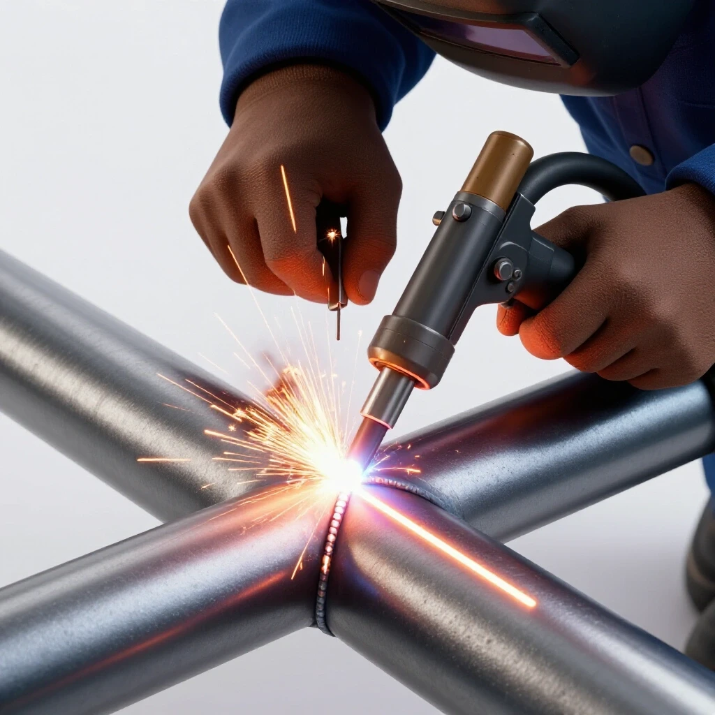
The Diagnostic Approach to Final Layer Uniformity
This framework involves the systematic observation of the arc and molten puddle to ensure the final weld bead covers the groove edges without excessive buildup or undercut. It requires a baseline understanding of how metal behaves under concentrated heat.
When I am called in to troubleshoot a fabrication line, I start with a “diagnostic baseline.” For a final weld layer on a pipe, this means checking the mechanical stability of the workpiece first. If the pipe is vibrating or moving even a fraction of an inch due to a loose clamp or a shaky stand, your bead will never be straight. I once spent three hours trying to fix a “porosity issue” on a large diameter roll, only to find that a nearby compressor was sending micro-vibrations through the floor, causing the welder’s hand to oscillate at a frequency that disrupted the shielding gas envelope.
Before you strike an arc for that final pass, ensure your work environment is controlled. This includes your body position. If you are straining to reach the top of the pipe, your muscles will fatigue, and your travel speed will become erratic. I recommend a “dry run” where you move your hand along the path of the weld without the arc. If your elbow hits a brace or your cable snags on a corner, you’ve identified a mechanical variable that needs fixing before the metal gets hot.
Identifying Variable Failures in Electrode Manipulation
This process involves analyzing how rod angle and weave width contribute to the final appearance and structural integrity of the weld surface. It is the core of manual diagnostic welding.
The most common error I see in pipe finishing is an inconsistent “work angle.” On a flat plate, this is easy to manage, but on a cylindrical surface, the angle is constantly changing relative to the ground. If you maintain a static hand position while moving around the pipe, your rod angle will eventually become too steep or too shallow. This leads to “cold lap,” where the molten metal sits on top of the pipe rather than fusing into it.
Troubleshooting Rod Angle and Arc Length
In my repair logs, I often note that “arc blow” or uneven bead profiles are caused by a rod that is trailing too far behind the puddle. For a clean finish, you want a slight “drag” angle—usually between 5 and 15 degrees. If you exceed this, the force of the arc pushes the molten metal forward, creating a hump in the center of the bead and leaving the edges starved.
| Symptom | Probable Cause | Diagnostic Test | Recommended Adjustment |
|---|---|---|---|
| Undercut at the edges | Travel speed too fast or arc too long | Measure arc length; it should be roughly the diameter of the rod core. | Slow down at the edges; tighten the arc. |
| Excessive convexity (Humping) | Travel speed too slow or rod angle too steep | Check the “drag” angle relative to the pipe’s tangent. | Increase travel speed; maintain a 10-degree drag. |
| Porosity in the cap | Shielding gas turbulence or long-arcing | Observe the distance between the rod tip and the puddle. | Keep the rod tip close; avoid “whipping” the rod. |
| Uneven bead width | Inconsistent weave timing | Use a metronome or mental count (1-2-hold, 1-2-hold). | Focus on holding the “corners” of the weave. |
Troubleshooting Travel Speed and Heat Input
This is the process of matching the rate of rod movement to the cooling rate of the puddle to prevent sagging or structural defects like “cold lap.” Heat management is the most difficult variable to master because it is invisible until the metal reacts.
If you move too slowly, the heat builds up in the pipe, causing the puddle to become too fluid. On a pipe, gravity is your enemy. If the puddle gets too hot, it will sag toward the bottom of the joint, creating a “grapes” effect or excessive reinforcement. Conversely, if you move too fast, the base metal doesn’t reach the “wetting” temperature, and the weld metal simply freezes on the surface without bonding.
I use a “count-based” diagnostic for travel speed. When performing a weave—which is common for a final finish—you must pause at the edges of the weld groove. This pause allows the heat to melt the “shoulders” of the groove, ensuring the metal flows in and fills the void. I tell my students to think of it like a “Z” pattern. You move across quickly, but you “anchor” at each side for a fraction of a second. If you don’t anchor, you get undercut. If you stay too long in the middle, you get a mountain of metal you’ll have to grind off later.
Case Study: The Sagging Cap on a 6-Inch Schedule 40 Line
I recall a project involving a series of 6-inch steel pipes where the welder was struggling with the 5G position (horizontal pipe, vertical weld). Every time he reached the “sides” of the pipe (the 3 o’clock and 9 o’clock positions), the weld would sag, leaving a thin spot at the top of the bead and a lump at the bottom.
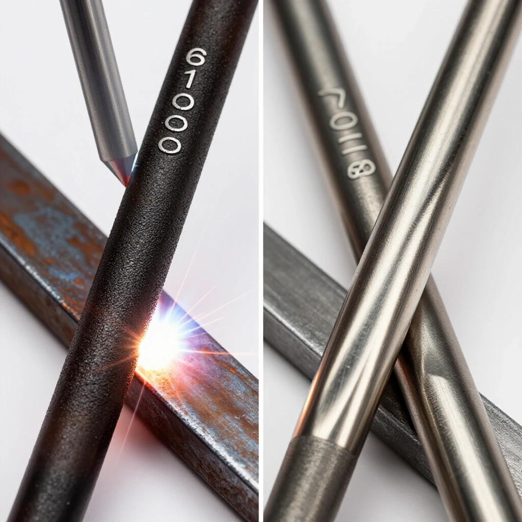
We treated this like a mechanical troubleshooting exercise. First, we checked the machine settings—they were within the manufacturer’s suggested range. Next, we looked at the electrode. He was using a standard 7018 rod. The issue wasn’t the equipment; it was the “puddle physics.”
- Observation: The puddle was too large for the gravity acting upon it at the 3 o’clock position.
- Isolation: We reduced the weave width by 15% and increased the travel speed slightly.
- Result: The sagging stopped, but he started getting undercut.
- Final Fix: We adjusted the rod angle to point slightly “up” into the top edge of the weave. This used the arc force to fight gravity, holding the molten metal in place until it solidified.
Mechanical Alignment and its Impact on Final Aesthetics
This section covers how the physical setup and alignment of the pipe sections dictate the difficulty of the finishing pass. Misalignment in the early stages often manifests as a “wandering” cap pass.
If your pipe sections are not perfectly concentric, one side of your weld groove will be higher than the other. This “high-low” condition is a nightmare for a neat finish. When you try to run your final bead, the arc will naturally want to jump to the closer piece of metal. This results in an off-center bead that looks unprofessional and may fail inspection.
I always use a digital dial indicator or a high-quality “line-up” clamp to ensure the pipe ends are within 0.010 inches of alignment. If you find yourself struggling to keep the bead centered, stop and measure the joint. If the pipe has warped during the previous passes, you may need to “compensate” by tilting your rod angle toward the “low” side to build up more material there.
A Checklist for Pre-Finish Alignment
- Check for pipe roundness using a wrap-around or a large caliper.
- Verify the “land” or the edge of the groove is consistent all the way around.
- Ensure the “tack welds” are ground down to a feather edge so they don’t cause a bump in your final pass.
- Use a magnetic level to find the “dead top” (12 o’clock) and “dead bottom” (6 o’clock) of the pipe and mark them with soapstone. These are your navigational waypoints.
Diagnosing Weld Porosity in the Final Layer
Weld porosity is the presence of tiny gas pockets or holes in the weld metal, often caused by contamination or improper arc technique. In a finishing pass, it is usually a sign of “long-arcing.”
When you reach the end of a project, it’s tempting to pull the rod away quickly to see your work. This increases the arc length. A long arc is unstable; it creates a wider, shallower puddle and allows atmospheric nitrogen and oxygen to enter the molten metal. This results in “pockmarks” on your beautiful finish.
To diagnose porosity, look at the shape of the holes. If they are clustered at the start of the bead, it’s likely a contaminated rod or base metal. If they are scattered throughout, you are likely holding the rod too far from the work. I recommend keeping the arc length no longer than the diameter of the electrode’s steel core—roughly 1/8 inch for a standard rod.
Real-World Guidelines for Bead Profile and Reinforcement
According to most fabrication standards (like the AWS D1.1), the reinforcement on a weld—the amount the metal sticks up above the surface—should generally not exceed 1/8 inch (3mm). Anything more than that is “excessive reinforcement” and can actually weaken the joint by creating a sharp transition point where cracks can start.
- Target Height: 1/16 inch to 1/8 inch.
- Target Width: 1/16 inch wider than the original groove on each side.
- Visual Uniformity: The “ripples” in the weld should be spaced evenly. This is a direct indicator of a steady travel speed.
If your bead is too wide, you are weaving too much. If it’s too narrow, you aren’t covering the edges of the groove. I use a “bridge cam gauge” to measure these values during my inspections. It’s a simple tool that removes the guesswork from the diagnostic process.
Essential Tools for Systematic Troubleshooting
To move from “guessing” to “knowing,” you need the right diagnostic tools in your box. These aren’t just for fixing machines; they are for fixing your technique.
- Welding Fillet Gauge: For measuring the leg length and convexity of the bead.
- Magnifying Hood Lens: If you can’t see the leading edge of the puddle, you can’t control it. I often find that “bad welding” is actually “bad vision.”
- Digital Infrared Thermometer: To check the “interpass temperature.” If the pipe gets too hot (above 500°F for some steels), the final pass will stay liquid too long and sag.
- Soapstone and Wrap-around: For marking perfectly straight guide lines on the pipe. Even the pros use “training wheels” when the stakes are high.
- Small Grinder with a Wire Wheel: To clean every single millimeter of the previous pass. Porosity often starts from a tiny speck of slag left behind.
Conclusion: The Path to Consistent Results
Mastering the final appearance of a pipe weld isn’t about having “golden hands.” It’s about becoming a diagnostic technician of your own movements. By isolating variables like rod angle, travel speed, and mechanical alignment, you turn a chaotic process into a predictable one.
The next time you face a pipe joint, don’t just start welding. Perform a dry run. Check your alignment. Set a mental rhythm for your weave. If the bead starts to look wrong, don’t just keep going—stop, diagnose the specific error (is it undercut? is it sagging?), and adjust your variables one at a time. This systematic approach is what separates the hobbyist from the specialist.
Frequently Asked Questions
Why does my final weld bead have “pinholes” even though I cleaned the metal?
Pinholes, or porosity, are often caused by a “long arc.” If you hold the rod too far from the pipe, the shielding gas cannot protect the molten metal from the air. Keep your arc tight—about the thickness of the rod itself. Also, ensure there is no draft or wind blowing away your shielding gas if you are working near a door or fan.
How do I stop the weld from sagging at the bottom of the pipe?
Sagging is a heat and gravity issue. To fix this, you can slightly reduce your amperage (by 5-10 amps) or increase your travel speed. Most importantly, use the arc force to your advantage by pointing the rod slightly upward. This “pushes” the metal against gravity until it freezes.
Why is there a “groove” or undercut at the very edge of my weld?
Undercut happens when the arc melts the base metal, but you move away before the filler metal has a chance to fill the hole. The fix is to “pause” for a split second at the edges of your weave. This allows the puddle to “wash in” and fill the area the arc just carved out.
What is the best weave pattern for a neat finish on a pipe?
For most DIY projects, a “Z-weave” or a slight “Crescent” motion is best. The goal is to move across the center of the weld quickly (to avoid a hump) and linger at the edges (to avoid undercut). Keep the width consistent by following a soapstone line.
How wide should my final pass be?
Ideally, your final pass should be about 1/8 inch wider than the original groove (1/16 inch on each side). This ensures that you have completely fused the edges of the pipe and provides a smooth transition from the weld to the base metal.
My weld ripples are spaced unevenly. What am I doing wrong?
Uneven ripples are a sign of inconsistent travel speed. You are likely moving in “jerks” rather than a smooth motion. Try to find a comfortable position where you can move your entire arm rather than just your wrist. Practicing your “dry run” will help build the muscle memory needed for a steady pace.
Can I use a wire brush to fix a lumpy weld?
A wire brush will clean the surface, but it won’t fix the shape of the metal. If the weld is truly lumpy or has “cold lap,” the only way to fix it properly is to grind the high spots down with a hard grinding disk and run another pass. This is why diagnosing the issue during the weld is so important.
Does the temperature of the pipe matter for the final pass?
Yes. If the pipe is already very hot from previous passes, the metal will stay molten longer, making it harder to control and more likely to sag. If the pipe is too hot to touch with a gloved hand for more than a second, let it cool down to about 250-300°F before starting your final layer.
Why does my rod keep sticking when I try to keep a tight arc?
This usually means your amperage is a bit too low, or you are “pushing” the rod into the puddle rather than hovering just above it. Try increasing your current by 5 amps, or focus on maintaining a consistent 1/8-inch gap.
How do I know if my rod angle is correct?
Look at the slag. If the slag is “peeling” up on its own as it cools, your angle and heat are usually spot on. If the slag is hard to remove and seems “stuck” in the edges, you likely have undercut or a rod angle that is too steep.
(This article was written by one of our staff writers, Paul Whitaker. Visit our Meet the Team page to learn more about the author and their expertise.)