How to Build a Sturdy Steel Frame Storage Bin Rack (DIY Plan)
I remember the first time I tried to build a large-scale shop organizer. I had my cut list ready, my MIG welder dialed in, and a stack of 1-inch angle iron. I spent four hours cutting and another three welding, only to realize by the end that the entire frame had twisted nearly two inches off-center. It looked more like a piece of abstract art than a functional storage unit. That project taught me a hard lesson: steel is a living thing when you apply heat to it. If you do not have a plan to manage that movement, the metal will always win.
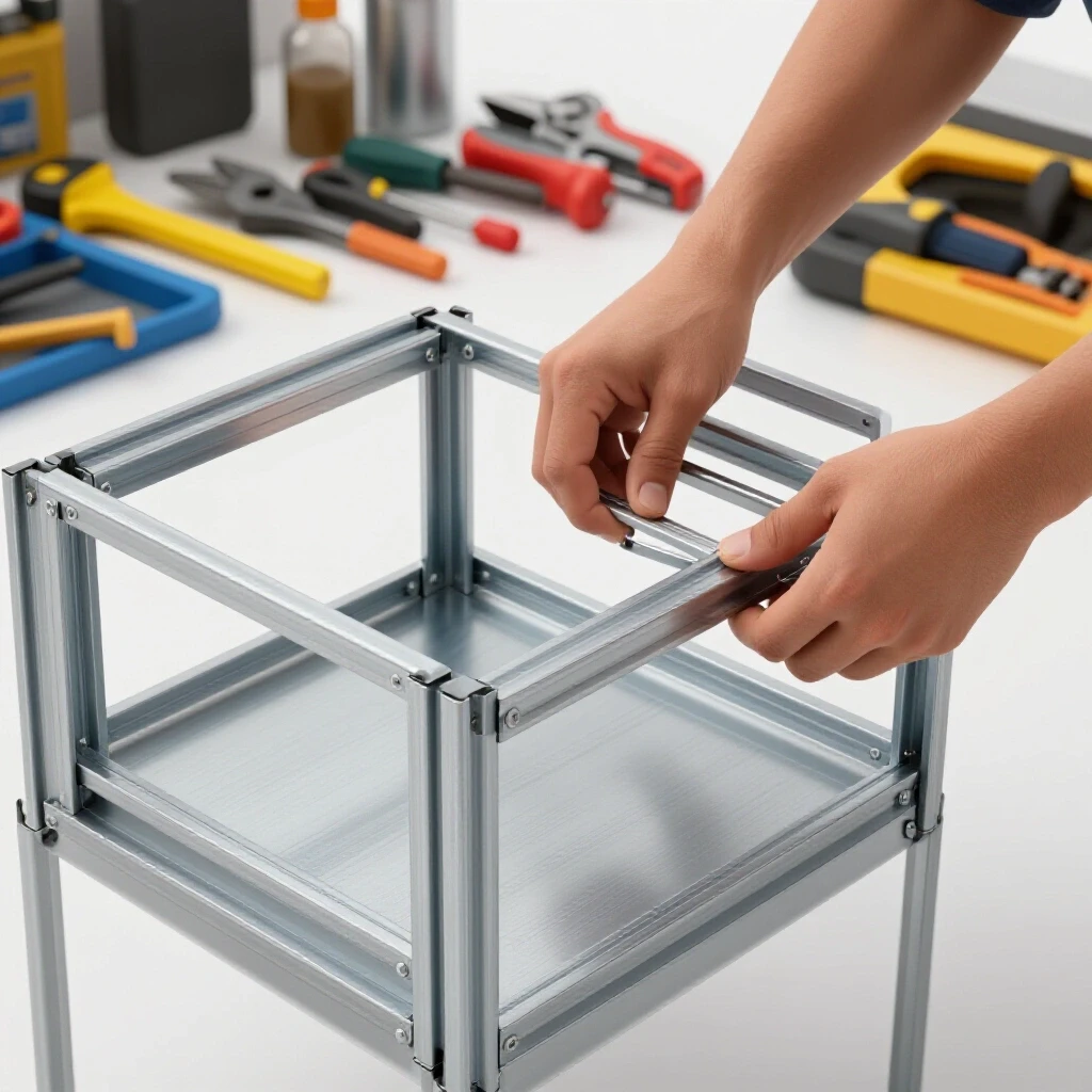
In my thirteen years as a prototype technician and fabricator, I have learned that the difference between a professional-grade build and a garage headache lies in the preparation. Whether you are building a utility trailer or a heavy-duty rack for organized bin storage, the physics remain the same. You are managing thermal expansion, contraction, and the mechanical limits of your materials. This guide focuses on the technical reality of building a straight, square, and structurally sound frame that will hold hundreds of pounds of hardware without buckling or leaning.
Designing the Framework and Calculating Precise Cut Lists
A cut list is a detailed inventory of every piece of metal needed for a project, including exact lengths and angles. It serves as the roadmap for the entire fabrication process, ensuring that material waste is minimized and that the final assembly matches the intended dimensions.
Before you strike an arc, you need a blueprint that accounts for the physical reality of the steel. For a unit designed to hold multiple rows of plastic bins, you must measure your containers first. I always add a 1/2-inch “wiggle room” to the total width of each shelf. This prevents the bins from binding against the weld beads in the corners. When you calculate your lengths, you must also account for the thickness of the metal itself. If you are building a frame that is 48 inches wide using 1/8-inch thick angle iron, your internal cross-members will not be 48 inches; they will be 47-3/4 inches.
Understanding Kerf Allowances for Accurate Sizing
Kerf is the width of the material removed by the cutting tool during the slicing process. Ignoring this measurement leads to cumulative errors where each subsequent piece is slightly shorter than the last, eventually throwing the entire frame out of square.
In my shop, I use a standard abrasive chop saw for most structural projects. These blades are usually 1/8-inch thick. If I need four pieces at 24 inches each, I cannot just mark 24, 48, 72, and 96 on a single stick of steel. By the time I hit the fourth cut, I will be nearly half an inch short because of the kerf. I always mark, cut, and then re-measure for the next piece.
| Cutting Tool Type | Average Kerf Width | Best Use Case |
|---|---|---|
| Abrasive Chop Saw | 0.125 inch (1/8″) | Heavy structural steel and thick angle iron |
| Cold Saw | 0.080 – 0.100 inch | Precision cuts with minimal heat input |
| Portable Band Saw | 0.025 – 0.035 inch | On-the-fly trimming and thin-wall tubing |
| Plasma Cutter | 0.040 – 0.060 inch | Non-linear shapes and thick plate |
Planning for Material Wall Thickness
Wall thickness refers to the gauge or fractional measurement of the metal’s skin. This dimension dictates the weight-bearing capacity of the rack and determines how much heat you can apply during welding without burning through the material.
For a rack intended to hold heavy bolts, car parts, or tools, I recommend 11-gauge (approximately 1/8-inch) square tubing for the uprights and 1/8-inch angle iron for the shelf rails. Thinner materials, like 16-gauge, are lighter and cheaper but tend to warp significantly more during the welding process. When you plan your joints, remember that a butt joint adds the thickness of one member to the overall dimension, whereas a miter joint keeps the outer dimensions true to your measurements.
Selecting Materials for Structural Integrity and Load Distribution
Material selection involves choosing the specific shapes and grades of steel that best resist bending and twisting under load. Proper selection ensures the storage system remains stable even when fully loaded with dense materials.
When I design a storage solution, I look at the “moment of inertia” for the steel shapes. Square tubing is excellent for vertical compression—the “legs” of your rack. It resists twisting (torsional force) better than angle iron. However, angle iron is the king of shelf supports. The “L” shape provides a natural ledge for bins to sit on, and it is much easier to weld into a ladder-style configuration.
Comparing Angle Iron versus Square Tubing
Angle iron consists of two legs at a 90-degree angle, while square tubing is a closed four-sided box. Each has specific mechanical advantages depending on whether the force is being applied vertically or horizontally.
For the shelf rails where the bins actually slide in and out, angle iron is the practical choice. I typically use 1-1/2″ x 1-1/2″ x 1/8″ angle. It provides a wide enough surface to catch the lip of the bin while staying rigid across a 4-foot span. For the vertical corners, 1-1/2″ square tubing provides a much more stable “spine” for the rack. It is harder to accidentally kick or bend a square tube leg than a single piece of angle iron.
- Square Tubing: High resistance to buckling; ideal for vertical posts.
- Angle Iron: Easy to clean, easy to weld shelf tabs; ideal for horizontal rails.
- Flat Bar: Only used for diagonal bracing to prevent “racking” or side-to-side swaying.
Calculating Load Limits for Steel Shelving
Load limit is the maximum weight a structure can safely support before the metal reaches its yield point, which is the stage where it permanently deforms.
A common mistake is overestimating what a long span of steel can hold. A 4-foot piece of 1/8-inch angle iron will start to sag in the middle if it is supporting 200 pounds of hardware. To combat this, I always include a center vertical support if the rack is wider than 48 inches. This cuts the span in half and increases the weight capacity exponentially.
Creating Layout Jigs and Workspace Fixtures
Jigs and fixtures are temporary tools or setups used to hold workpieces in the exact desired position during the assembly process. They act as a “third hand” to maintain squareness and prevent parts from shifting during tack welding.
You cannot build a straight frame on an uneven floor. If your garage floor has a drain slope, your rack will have a built-in twist. I use a dedicated welding table, but if you are working on a budget, you can create a temporary fixture using a sheet of 3/4-inch plywood topped with a thin sheet of sacrificial steel. The goal is to have a flat reference plane where you can clamp your pieces down.
Building a Simple Corner Jig
A corner jig is a basic fixture that holds two pieces of metal at a perfect 90-degree angle. It can be as simple as two heavy blocks of steel bolted to a table or a dedicated commercial welding clamp.
In my shop, I often make “L-jigs” out of scrap 2×2 tubing. I weld two pieces into a perfect 90-degree “L” and check it with a machinist’s square. I then clamp my project pieces into the inside of that “L.” This ensures that when I place my first tack welds, the corner cannot pull inward as the metal cools. If you don’t use a jig, the cooling weld will naturally pull the joint shut, turning your 90-degree corner into 88 degrees.
Using Clamps to Fight Thermal Movement
Clamping is the process of using mechanical pressure to lock workpieces against a fixture. This prevents the metal from moving as it expands from the heat of the welding arc.
- C-Clamps: Provide the highest pressure for thick materials.
- F-Clamps (Sliding Clamps): Allow for quick adjustments across long spans.
- Locking Pliers (Vice-Grips): Good for quick tacks but can slip under high heat.
- Copper Heat Sinks: Clamping a piece of copper behind a joint helps dissipate heat and prevents burn-through.
Mastering the Art of Square Tacking and Initial Fit-Up
Tack welding involves placing small, localized beads of weld to hold a structure together. These tacks must be strong enough to resist the cooling forces of the metal but small enough to be easily removed or welded over during the final pass.
Once your pieces are clamped in the jig, do not just start welding the entire seam. You need to “tack” the project together first. I place 1/4-inch tacks on the corners. For a standard shelf joint, I place one tack on the top and one on the bottom. I never tack the “inside” of the corner first, as this is where the most shrinkage occurs.
The Diagonal Rule for Squaring Frames
The diagonal rule states that if a rectangular frame is perfectly square, the distance between opposite corners (A to C and B to D) will be exactly equal.
After I have tacked the four corners of a shelf level, I take my tape measure and check the diagonals. If one side is 60-1/8 inches and the other is 60-3/8 inches, the frame is a parallelogram. I use a large bar clamp to squeeze the “long” diagonal until the measurements match. Only once the diagonals are within 1/16 of an inch do I proceed with more tacks.
- Measure from top-left to bottom-right.
- Measure from top-right to bottom-left.
- Compare the two numbers.
- Apply pressure to the longer dimension to “squish” it into square.
- Add secondary tacks to lock the new position.
Sizing Tacks for Structural Stability
A tack weld that is too small will “pop” or crack as the rest of the frame is assembled. A tack that is too large becomes a hump that interferes with the final weld bead.
For 1/8-inch steel, a tack should be about the size of a pencil eraser. If you are using a MIG welder, a “one-Mississippi” count is usually enough. If you are using a stick welder, ensure you have good penetration; a cold tack will simply sit on top of the mill scale and fail the moment you try to adjust the frame.
Controlling Heat Warp Through Strategic Weld Sequencing
Weld sequencing is the planned order in which welds are applied to a structure. By alternating sides and locations, a fabricator can balance the pulling forces of cooling metal to keep the overall project straight.
Heat is the enemy of a straight frame. When you weld, the steel becomes molten. As it cools, it shrinks. If you weld the entire front side of your storage rack all at once, the cooling metal will pull the uprights inward, creating a “bow-tie” shape. To prevent this, you must distribute the heat evenly across the entire structure.
The “Mirroring” Technique for Distortion Control
Mirroring involves performing a weld on one side of a joint and then immediately performing the exact same weld on the opposite side or the opposite end of the frame.
If I weld the top-left corner of the rack, my next weld isn’t the bottom-left. Instead, I move to the bottom-right. By jumping across the frame, I allow the first weld to cool while the second weld pulls in the opposite direction. This “tug-of-war” keeps the frame centered.
| Weld Sequence Step | Location | Purpose |
|---|---|---|
| 1 | Top-Left Outer Corner | Establish primary anchor point |
| 2 | Bottom-Right Outer Corner | Counter-pull against Step 1 |
| 3 | Top-Right Outer Corner | Establish secondary anchor point |
| 4 | Bottom-Left Outer Corner | Counter-pull against Step 3 |
| 5 | Center Rails (Alternating) | Distribute heat across the “ladder” |
Managing Angular Distortion in T-Joints
Angular distortion occurs when a weld bead is placed on one side of a vertical member, causing it to lean toward the weld. This is a major issue when attaching shelf rails to upright posts.
When you weld a shelf rail to an upright, the vertical post will want to lean toward the rail. To combat this, I often “pre-set” the joint. I might clamp the post so it leans 1 or 2 degrees away from the shelf. When the weld cools, it pulls the post perfectly vertical. Alternatively, you can use “back-stepping,” where you weld in short 2-inch segments, moving in the opposite direction of the overall bead travel.
Correcting Distortion and Ensuring Final Alignment
Final alignment is the process of inspecting the completed structure for any warping and using mechanical or thermal methods to bring it back into specification.
Even with the best sequencing, some movement is inevitable. Once the welding is complete, let the frame cool naturally. Never throw water on a hot weld to speed up the process; this makes the steel brittle and can cause the welds to crack. Once cool, I perform a final check with a 4-foot level and a framing square.
Using Mechanical Force for Straightening
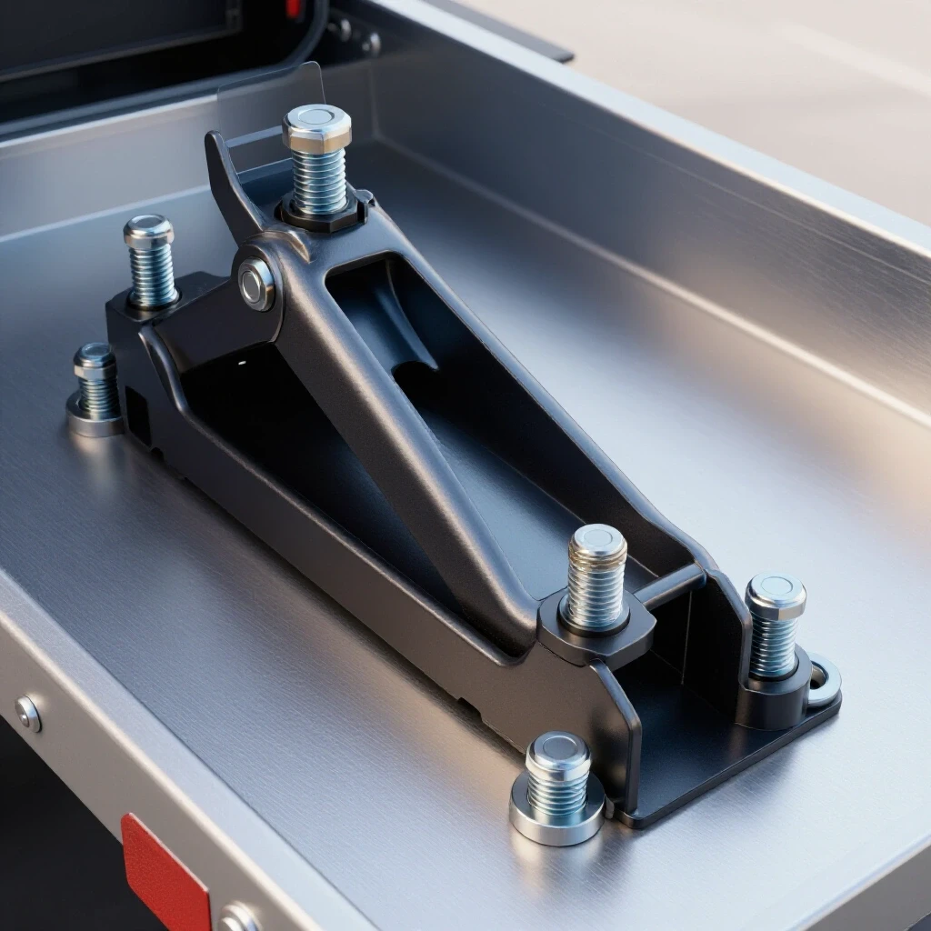
If a leg has bowed inward by 1/4 inch, you can often “cold-straighten” it using a hydraulic bottle jack or a heavy-duty port-a-power.
I place the jack between the two bowed members and slowly apply pressure until they are slightly past the “straight” point. Steel has an elastic limit; you have to push it a bit further than you want it to go so that it “springs back” to the correct position. Be careful not to over-stress the welds during this process. If you hear a “ping” sound, stop immediately—you have cracked a weld.
The Use of Heat Shrinking for Precision Fixes
Heat shrinking is a technique where a small area of metal is heated with a torch to cherry red and then allowed to cool, using the metal’s own contraction to pull a warped section back into alignment.
If a shelf rail is “humped” upward, you can heat a small triangle on the underside of the rail. As that red-hot triangle cools, it will shrink more than the surrounding cold metal, pulling the hump back down. This is an advanced technique that requires patience. In a garage setting, it is usually better to rely on smart clamping and sequencing to avoid needing this step entirely.
- Identify the “high” side of the warp.
- Apply heat to the “long” side of the curve.
- Allow to air cool (do not quench).
- Re-measure and repeat if necessary.
Final Assembly and Load Distribution Strategies
The final phase involves adding the finishing touches, such as feet or casters, and verifying that the structure can handle the intended weight distribution of the storage containers.
Before I call a project finished, I look at how the rack touches the floor. A tall storage unit filled with heavy bins can be top-heavy. I always weld 3″ x 3″ squares of 1/4-inch plate to the bottom of the legs. These “feet” distribute the weight so the steel doesn’t dig into the concrete, and they provide a great place to drill holes for floor anchors.
Adding Cross-Bracing for Lateral Stability
Cross-bracing involves adding diagonal members to a rectangular frame to prevent it from collapsing sideways under a “shear” load.
A frame might be strong vertically, but if you push it from the side, it can “rack” or fold over. I add 1-inch flat bar diagonals to the back of the rack. These should form an “X” shape across the largest open span. This triangulates the structure, making it incredibly rigid. Even a thin piece of flat bar, when used as a diagonal, can increase the lateral strength of a rack by over 500%.
Verification and Post-Weld Inspection
Inspection is the systematic check of all weld joints for cracks, porosity, or undercut, ensuring the rack is safe for use.
- Visual Check: Look for “pinholes” in your welds. These are signs of gas coverage issues and can weaken the joint.
- Squareness Check: Use a framing square on every shelf level.
- Level Check: Ensure the uprights are “plumb” (perfectly vertical).
- Load Test: Place your heaviest bins on the bottom shelf first, then gradually fill the upper levels while watching for any signs of deflection.
Building a high-quality storage solution is more about managing physics than it is about having the most expensive welder. By respecting the way heat moves through steel and taking the time to build accurate jigs, you can create workshop fixtures that are straighter and stronger than anything you could buy.
FAQ: Common Challenges in Steel Frame Fabrication
How do I prevent the bottom of my rack from wobbling on an uneven floor? The best solution is to weld threaded nuts into the bottom of your square tubing legs. You can then thread in heavy-duty leveling feet (bolts with wide plastic or metal bases). This allows you to adjust each corner independently to match the contour of your garage floor.
What is the best way to weld thin-wall tubing without burning holes? Use the “stitch” method. Instead of one long continuous bead, make a series of overlapping tacks. This keeps the overall temperature of the base metal lower. Also, ensure your wire speed is high enough; if it’s too low, the arc stays in one place too long and melts through.
Should I paint the steel before or after welding? Always after. You cannot weld through paint without creating toxic fumes and weak, porous welds. Clean the steel with acetone or a degreaser after fabrication, then apply a self-etching primer followed by a durable topcoat.
How much weight can a 1/8-inch thick angle iron shelf hold? Over a 4-foot span, a pair of 1-1/2″ x 1/8″ angle iron rails can safely support about 250-300 pounds of distributed weight before noticeable deflection occurs. If you need to hold more, add a vertical support in the center.
Why did my frame pull out of square even though I clamped it? You likely removed the clamps while the metal was still “black hot.” Steel continues to shrink until it reaches room temperature. Keep your clamps on until the joint is cool enough to touch with your bare hand.
What is the “3-4-5 rule” for squaring large racks? If you measure 3 feet down one side and 4 feet down the connecting side, the diagonal between those two points must be exactly 5 feet. This is a quick way to check squareness on projects too large for a standard framing square.
Can I build this with a 110v welder? Yes, but you are limited by the duty cycle. For 1/8-inch steel, a 110v MIG welder is usually at its upper limit. Take your time, let the machine rest between shelves, and ensure you are plugged into a 20-amp circuit to avoid voltage drops that cause “cold” welds.
How do I stop the “L” shape of the angle iron from twisting when I weld it? Angle iron is notorious for twisting. Always weld from the “root” (the inside corner) outward. If you weld the tips of the legs first, the root will pull and twist the entire length of the bar.
Is it better to miter the corners or butt-joint them? Miter joints (45-degree cuts) look cleaner and provide more surface area for the weld, but they are harder to cut accurately. Butt joints are much easier for beginners and are just as strong if you account for the material thickness in your cut list.
How do I get clean cuts with a cheap abrasive saw? Don’t push too hard. Let the weight of the saw do the work. If you force it, the blade will flex, resulting in a cut that is not square. Also, replace the blade once it wears down to half its original diameter, as smaller blades have more “run-out.”
(This article was written by one of our staff writers, Robert Kline. Visit our Meet the Team page to learn more about the author and their expertise.)