How to Build a Mobile Steel Engine Hoist Frame (DIY Guide)
I remember the first time I tried to build a heavy-duty shop fixture. I had spent hours measuring every piece of square tubing, ensuring my 45-degree miters were tight enough to hold a piece of paper. The moment I finished the final bead on the base frame, I stepped back to admire my work, only to find one leg sitting a full half-inch off the garage floor. The heat from my welder had pulled the steel into a gentle but devastating curve. It was a humbling lesson in the physics of metal: steel is never static when heat is involved.
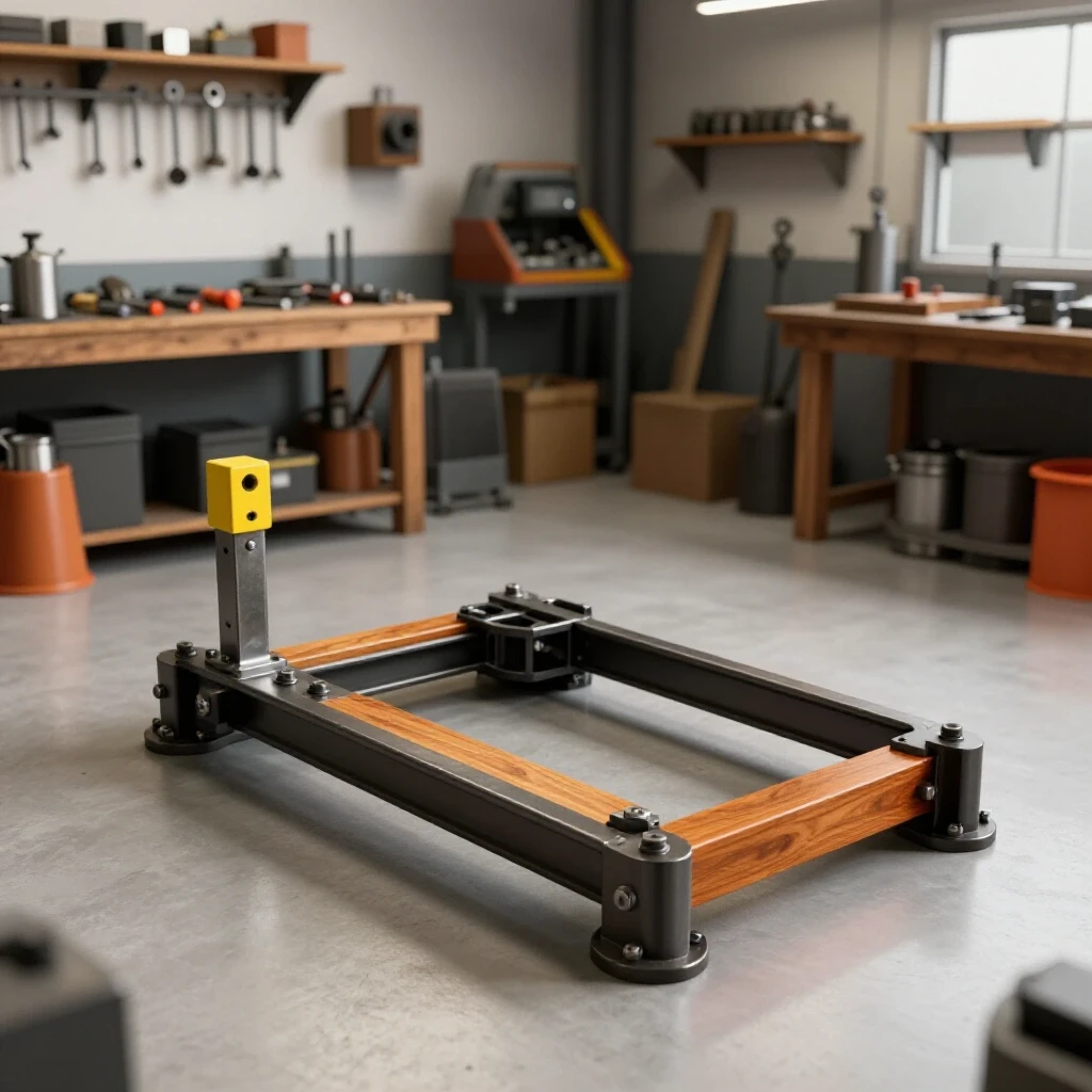
In my thirteen years as a prototype technician, I’ve learned that a successful custom fabrication project isn’t just about the quality of your welds. It is about how you manage the forces of thermal expansion and contraction. When you are constructing a mobile lifting structure designed to hold hundreds of pounds, those forces can ruin your alignment and compromise the structural integrity of the frame. This guide focuses on the practical steps to plan, cut, and assemble a rolling steel frame while keeping it square and true.
Designing the Cut List and Selecting Structural Material
Creating a reliable lifting frame starts with choosing the right raw materials and planning your cuts to minimize waste. For a shop-built crane, we typically look at Hollow Structural Sections (HSS), commonly known as square or rectangular steel tubing.
Selecting the right wall thickness is a balance between weight and rigidity. For most utility projects, A36 mild steel is the standard. I prefer using 3/16-inch or 1/4-inch wall thickness for the main uprights and the base. Thinner material, like 1/8-inch, is easier to weld with hobbyist machines but lacks the torsional stiffness required for a tall, mobile frame.
Understanding Material Yield and Load Basics
Before you buy your steel, you need to understand how much stress the material can handle before it deforms permanently. This is known as the yield strength. Most A36 steel has a yield strength of about 36,000 psi. However, in a DIY environment, we always overbuild to account for the “real world” of imperfect welds and uneven floors.
- 2″ x 4″ Rectangular Tubing (3/16″ wall): Excellent for the main boom where vertical loads are highest.
- 3″ x 3″ Square Tubing (3/16″ wall): Ideal for the base and uprights to resist twisting.
- 1/2″ Steel Plate: Used for caster mounts and gussets to distribute stress at the joints.
Accounting for Kerf and Layout Accuracy
One of the biggest mistakes I see in garage builds is failing to account for the kerf. The kerf is the width of the material removed by your cutting tool. If you use a standard abrasive chop saw, you are losing about 1/8 of an inch with every cut. If you have ten cuts in a row, your final piece could be over an inch short if you didn’t plan ahead.
When I’m laying out a mobile frame, I use a “measure once, cut once, but mark twice” approach. I mark my first cut, execute it, and then measure the remaining stock for the next piece. This prevents the cumulative error that happens when you mark all your pieces at once based on a blueprint.
Metal Kerf Allowances by Cutter Type
| Cutting Tool | Typical Kerf Width | Best Use Case |
|---|---|---|
| Abrasive Chop Saw | 0.125″ (1/8″) | Rough structural cuts |
| Cold Saw | 0.090″ – 0.110″ | Precision miters, low heat |
| Horizontal Band Saw | 0.035″ – 0.050″ | High accuracy, slow speed |
| Plasma Cutter | 0.040″ – 0.060″ | Plate steel, gussets |
| Oxy-Acetylene Torch | 0.100″ – 0.150″ | Thick plate, dismantling |
To maintain a dimensional tolerance of +/- 1/16th inch, I recommend using a scribe rather than a thick carpenter’s pencil. A sharp line is the difference between a joint that fits tight and one that requires a massive “bridge” weld to fill the gap.
Building Workshop Jigs and Layout Fixtures
You cannot build a square frame on an unlevel floor. Most garage floors are sloped for drainage, which means if you lay your steel directly on the concrete, your frame will be built with a built-in twist. To combat this, I use a series of adjustable layout fixtures or “jack stands” made from scrap steel.
A layout fixture is any device that holds your workpieces in the same plane during the tack-welding process. For a mobile frame base, I set up four points that are perfectly level with each other using a laser level or a long straightedge. By shimming these points, I create a “virtual” flat table.
- Step 1: Place your base rails on the leveled stands.
- Step 2: Use a large framing square to check the corners, but verify the squareness by measuring the diagonals.
- Step 3: If the distance from the front-left corner to the back-right corner is identical to the other diagonal, your base is square.
- Step 4: Secure the pieces with heavy C-clamps or F-clamps to prevent them from shifting during the first tacks.
Why Weld Shrinkage Warps Square Structures
When you weld, you aren’t just joining two pieces of metal; you are applying localized heat that causes the steel to expand. As the weld pool cools, it shrinks. This shrinkage acts like a tiny, powerful winch, pulling the two pieces toward the side where the weld was placed. This is known as angular shrinkage.
In a custom fabrication project, if you weld the entire outside of a joint first, the shrinkage will pull the upright out of square. To manage this, we use a specific weld sequencing layout. By placing welds in a balanced order, the shrinkage forces of one bead counteract the forces of the next.
Angular Weld Shrinkage Rates
| Material Thickness | Shrinkage Force (Approx) | Typical Distortion Angle |
|---|---|---|
| 1/8″ (11ga) | Low | 1.5 – 2.0 degrees |
| 3/16″ (0.188) | Medium | 1.0 – 1.5 degrees |
| 1/4″ (0.250) | High | 0.5 – 1.0 degrees |
Interestingly, thicker material resists bending better but exerts more force on your clamps. This is why “tack welding” is the most critical stage of the assembly.
Strategic Tacking and Structural Sequencing
A tack weld is a small, temporary weld intended to hold components in alignment until the final passes are made. For a structural frame, your tacks need to be substantial—usually about 1/2 inch long for 3/16-inch material. I place tacks at the center of each side of a joint rather than at the corners.
When I move to the final welding phase, I follow a strict sequence. For a square tube joint, I never weld all four sides in a circle. Instead, I weld side A, then move to the opposite side (side C). This balances the heat. If I weld side A and then side B (the adjacent side), the combined pull will yank the part diagonally.
- Tack all four corners of the main frame.
- Re-measure diagonals to ensure the tacks didn’t pull the frame out of square.
- Weld the “inside” joints first. This allows the frame to be “pulled” inward, where the cross-members provide resistance.
- Weld the “outside” joints last.
- Allow the metal to cool completely before removing your clamps. Removing clamps while the steel is still “red-hot” or even “blue-warm” is a recipe for instant warping.
Executing the Main Upright and Boom Assembly
The vertical mast and the lifting boom are the heart of a mobile lifting frame. These components see the most stress. Because the boom is often a long, cantilevered arm, even a tiny amount of weld distortion at the base can translate into a boom tip that is inches off-center.
To keep the upright perfectly vertical, I use a technique called “pre-setting.” If I know a weld will pull the upright two degrees to the left, I will clamp it two degrees to the right before I start. This is an advanced move that takes practice. For most builders, the safer bet is to use heavy gussets.
Gusset Placement and Heat Sinks
Gussets are triangular pieces of plate steel used to reinforce a joint. They are excellent metal warping solutions because they provide a massive amount of surface area to resist the pull of the weld. When I weld gussets on a lifting frame, I start from the center of the gusset and weld toward the outer edges.
If you are worried about heat buildup, you can use a heat sink. A thick block of copper or even a large piece of scrap aluminum clamped near the weld zone can help pull heat away from the steel, reducing the size of the Heat-Affected Zone (HAZ). A smaller HAZ means less overall distortion.
Adding Mobility: Caster Attachment and Alignment
A mobile frame is only as good as its wheels. For a lifting structure, I always use heavy-duty steel or polyurethane casters with a weight rating that exceeds the total expected load by at least 50%. This “safety factor” accounts for dynamic loads—like when you’re pushing the frame over a crack in the garage floor.
When welding caster plates to the bottom of the base, the heat can warp the plate, making the caster sit at an angle. This causes “death wobble” when you try to move the frame. To prevent this:
- Bolting vs. Welding: I prefer welding a 1/2-inch thick mounting plate to the frame and then bolting the caster to that plate.
- Sequence: Weld the mounting plate using a “stitch weld” pattern—2 inches of weld, 2 inches of gap—to keep the plate flat.
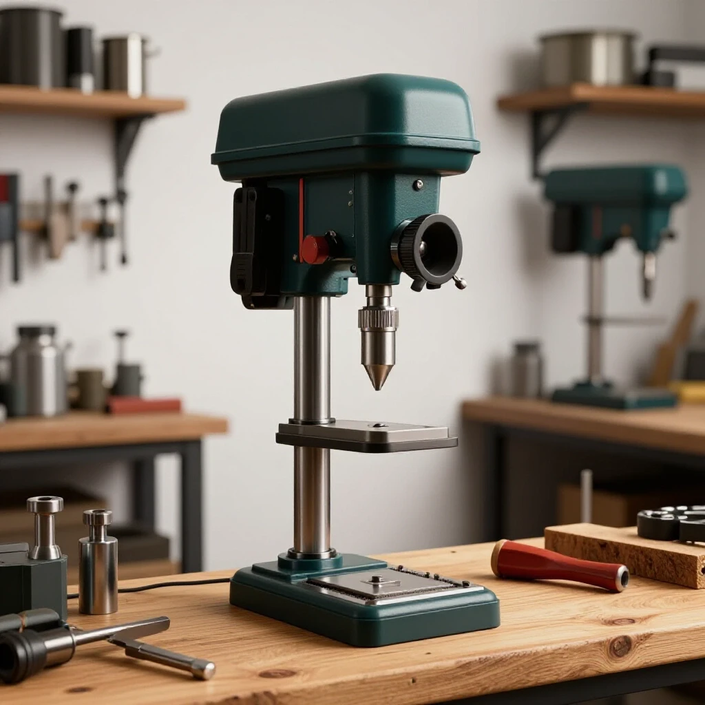
- Drilling: Drill your bolt holes in the plate before welding it to the frame. It is much easier to use a drill press on a small plate than to use a hand drill on a completed 200-pound frame.
Correcting Heat Distortion and Final Straightening
Even with the best planning, metal moves. If you find that your boom is slightly crooked or the base has a “rock” to it, don’t panic. There are ways to correct this without cutting the project apart.
One method is “flame straightening.” By applying heat to the side opposite the warp, you can cause that side to expand and then shrink, pulling the piece back into alignment. This requires a torch and a lot of patience. A more mechanical approach for DIY builders is using a hydraulic jack and some heavy chains to “cold bend” the frame back into square.
- Check 1: Level the base on a known flat surface.
- Check 2: Use a plumb bob dropped from the tip of the boom to the center of the base.
- Check 3: Ensure all casters touch the ground simultaneously.
Actionable Framework for a Successful Build
To keep your project on track, I recommend using a build log. This isn’t just for record-keeping; it’s a tool to prevent mistakes.
- Material Log: Track every piece of steel, its length, and its cost.
- Cut List Checklist: Check off each piece as it is cut and labeled.
- Weld Map: Draw a simple diagram of your joints and number the order in which you will weld them.
- Tolerance Log: Record your measurements before and after welding each major section. If you see the frame moving 1/8th of an inch, you can adjust your next weld to pull it back.
Building a durable, straight, and mobile lifting frame is a rite of passage for many fabricators. It requires you to stop thinking like a “welder” and start thinking like an “assembler.” When you respect the heat and plan for the movement of the steel, you end up with a tool that will serve your shop for decades.
Frequently Asked Questions
What is the best way to ensure my frame stays square during welding?
The most effective way is to use a combination of diagonal measurements and heavy fixturing. Always measure the distance between opposite corners (X-measuring). If the two distances are equal, the frame is square. Use heavy-duty C-clamps and tack-weld all corners before laying down any continuous beads.
Can I use a standard MIG welder for a structural lifting frame?
Yes, provided the welder has enough amperage to achieve proper penetration on 3/16″ or 1/4″ steel. For these thicknesses, a 220V welder is generally required. If you only have a 110V machine, you may need to use multi-pass welds and pre-heat the joints with a torch, though this is less than ideal for structural integrity.
Why did my steel tubing bow in the middle after welding the ends?
This is usually caused by “longitudinal shrinkage.” As the weld on the ends cools, it pulls the outer “skin” of the tube. If you only weld on one side of the tube, it will bow. To prevent this, balance your welds by alternating sides frequently to keep the heat input symmetrical.
How do I calculate the kerf for my specific saw?
The easiest way is to take a scrap piece of metal, measure its length exactly, make one cut, and then measure the two resulting pieces. Subtract the combined length of the two new pieces from the original length. The difference is your kerf. For a standard chop saw, this is usually 0.125 inches.
Is it better to miter the corners or use butt joints?
Mitered corners (45 degrees) look cleaner and provide more weld surface area, but they are harder to align and more prone to “walking” during welding. Butt joints (90 degrees) are easier to cut and clamp, making them a more practical choice for many DIY utility projects.
What size casters should I use for a mobile frame?
Look for casters with a “static load rating” that is significantly higher than your intended lift capacity. For a frame designed to lift 1,000 lbs, I recommend four casters each rated for at least 500-750 lbs. This accounts for the weight of the steel frame itself and the uneven distribution of weight while moving.
How do I prevent the “death wobble” on my rolling frame?
Wobble is usually caused by casters that are not mounted on the same plane. Ensure your base frame is perfectly flat before welding the caster plates. If one caster is higher than the others, you can use thin steel shims between the caster and the mounting plate to level it out.
Should I paint or powder coat the frame?
For a shop tool, a high-quality self-etching primer followed by a durable enamel “chassis paint” is usually sufficient. Powder coating is excellent but can be expensive and makes it difficult to weld on future modifications or repairs.
How many tack welds are necessary for a 3-inch square tube joint?
I recommend at least four tacks—one in the center of each flat side. For structural joints, make these tacks about 1/2-inch to 3/4-inch long to ensure they don’t “pop” when the metal begins to move during the final welding passes.
What is the “heat-affected zone” and why does it matter?
The HAZ is the area of metal around the weld that didn’t melt but was heated enough to change its microstructure. This area is often slightly weaker or more brittle than the base metal. By using proper weld sequencing and not over-welding, you can keep the HAZ small and maintain the strength of your steel.
(This article was written by one of our staff writers, Robert Kline. Visit our Meet the Team page to learn more about the author and their expertise.)