How to Calculate Safe Hole Spacing From Steel Edges (Tips)
I still remember a cold Tuesday morning in 2011 when a heavy equipment rack I had designed suffered a catastrophic failure during a load test. It did not break at a weld or bend in the middle. Instead, a single 1/2-inch bolt ripped through the edge of a steel mounting plate like a hot knife through butter. I had placed the hole too close to the edge of the plate, thinking the thickness of the steel would compensate for the lack of margin. That mistake cost me three days of rework and a significant blow to my professional pride.
In my 14 years of metal fabrication and mechanical engineering, I have learned that steel is incredibly strong until you give it a reason to fail. Holes are necessary for fasteners, but every hole is a deliberate “wound” in the material. If you place these holes too close to the edge or too close to each other, you create a path of least resistance for the metal to tear. This article is born from those hard lessons and thousands of hours on the shop floor, designed to help you avoid the frustration of wasted material and structural instability.
Understanding Structural Metal Load Capacity and Edge Clearance
Structural metal load capacity refers to the maximum stress a steel component can withstand before it deforms or breaks. When we drill holes near an edge, we reduce the amount of material available to resist those forces. Understanding these limits prevents the steel from tearing or failing under pressure by ensuring enough “meat” remains around every fastener.
When you apply a load to a bolted joint, the force is transferred from the bolt to the side of the hole. This creates a high concentration of stress. If the hole is too close to the edge, the small strip of metal between the hole and the boundary of the plate cannot handle the tension. This leads to a failure known as “tear-out.” In my experience, most hobbyists underestimate how much material is needed to prevent this.
The yield strength of common A36 structural steel is about 36,000 PSI. While that sounds like a lot, a narrow margin of steel can reach that limit surprisingly fast under a levered load. To keep your projects safe, you must consider the “shear path.” This is the imaginary line where the metal would split if the bolt were forced through the edge. By increasing the distance from the hole to the edge, you lengthen that path and increase the force required to cause a failure.
The Mechanics of Edge Distance and Material Tearing
Calculating the minimum edge distance involves determining the specific gap required between a hole’s center and the physical boundary of the steel plate. This measurement ensures that the surrounding metal remains strong enough to prevent the fastener from pulling through the edge when a load is applied. It is a fundamental step in ensuring structural reliability.
A common industry standard for general fabrication is the “1.5x Rule.” This means the distance from the center of the hole to the edge of the steel should be at least 1.5 times the diameter of the bolt. For example, if you are using a 1/2-inch bolt, the center of your hole should be at least 3/4 of an inch from the edge. However, this is a minimum. In my shop, I prefer a “2x Rule” whenever possible, especially for parts that will see vibration or heavy loads.
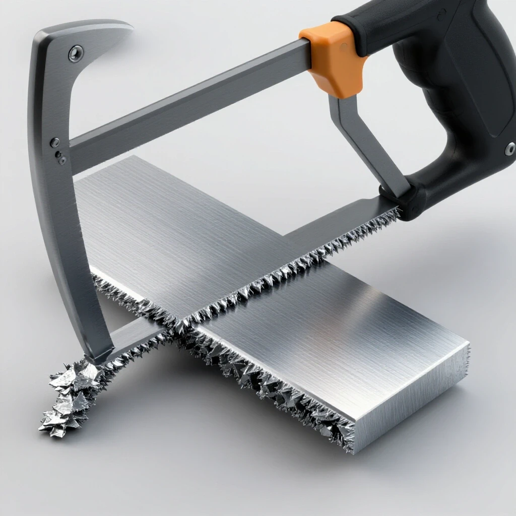
The type of edge also matters. A “sheared” edge, which is cut by a large industrial machine, often has microscopic cracks that can act as starting points for a tear. A “rolled” edge or a cleanly machined edge is slightly more stable. If you are working with a sheared edge, I recommend adding an extra 1/8 of an inch to your clearance to account for those hidden imperfections.
| Bolt Diameter | Minimum Edge Distance (1.5x) | Recommended Safety Margin (2x) |
|---|---|---|
| 1/4″ | 3/8″ | 1/2″ |
| 3/8″ | 9/16″ | 3/4″ |
| 1/2″ | 3/4″ | 1″ |
| 5/8″ | 15/16″ | 1 1/4″ |
| 3/4″ | 1 1/8″ | 1 1/2″ |
Why Heat Affected Zone Weakness Impacts Hole Integrity
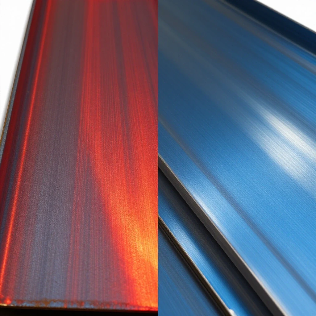
Heat affected zone weakness occurs when the thermal energy from cutting or welding alters the internal structure of the steel. This change often makes the metal around a hole more brittle or softer than the rest of the plate, increasing the risk of cracks or structural failure. This is particularly relevant if you use a plasma cutter or torch to make holes.
I have seen many fabricators use a plasma cutter to quickly “blow a hole” in a plate. While fast, the intense heat changes the metallurgy of the steel immediately surrounding that hole. This area, the Heat Affected Zone (HAZ), can become brittle. If that hole is also close to an edge, the brittleness makes it much more likely to crack under stress.
Whenever I am building something that requires high structural integrity, I drill my holes rather than burning them. Drilling is a “cold” process that does not alter the grain structure of the steel. If you must use a torch or plasma cutter, try to cut the hole undersized and then use a reamer or a drill bit to take it to the final size. This removes the brittle HAZ material and leaves you with a much stronger joint.
Workshop Safety Checklist for Layout and Drilling
A workshop safety checklist for layout and drilling provides a systematic way to verify measurements and tool settings before making permanent cuts. By following a structured process, fabricators can catch errors in hole placement or material alignment, significantly reducing the chance of wasted steel or accidents. Precision in the layout phase is the best defense against structural failure.
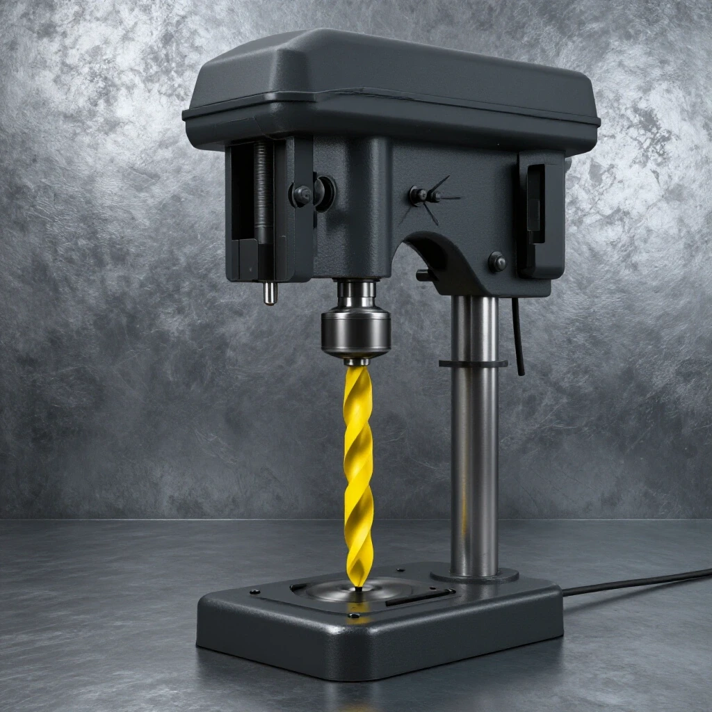
Before I even touch a drill press, I go through a mental and physical checklist. It is easy to get in a hurry, but a hole drilled in the wrong place is a permanent mistake. I start by cleaning the steel surface with a wire brush or a flap disc to remove mill scale. This allows my layout lines to be accurate and visible.
- Verify material thickness and bolt grade against your design.
- Mark the center of each hole using a high-quality scribe and a steel square.
- Use a center punch to create a deep divot for the drill bit to follow.
- Check the edge distance twice using a set of calipers.
- Ensure the workpiece is securely clamped to the drill press table.
- Wear appropriate PPE, including impact-rated safety glasses and hearing protection.
In my garage fabrication safety routine, I also pay attention to how the drill bit interacts with the metal. If the bit “wanders” toward the edge, it can ruin your calculated clearance. Always start with a small pilot bit to ensure the final hole stays exactly where you planned it.
Troubleshooting Common Fabrication Failures in Joint Preparation
Troubleshooting common fabrication failures involves identifying the root causes of issues like edge tearing, hole elongation, or cracking. By analyzing why a joint failed, a fabricator can adjust their design and drilling techniques to ensure future projects are more durable and meet safety standards. Learning from mistakes is what turns a hobbyist into a master.
One issue I frequently see is “hole elongation.” This happens when the bolt is slightly smaller than the hole, and the constant shifting of the load causes the bolt to hammer against the side of the hole. Over time, the round hole becomes an oval. This movement creates shock loads that can eventually cause the edge of the steel to fail, even if your initial spacing was correct.
To prevent this, I always aim for a “close fit” hole. If you are using a 1/2-inch bolt, use a 17/32-inch drill bit rather than a 9/16-inch bit. This extra 1/32 of an inch gives you just enough room to get the bolt through without leaving too much space for movement. If you find that a hole has already begun to elongate, the safest fix is usually to weld the hole shut, grind it flush, and redrill it with better spacing.
| Failure Type | Common Cause | Corrective Action |
|---|---|---|
| Edge Tearing | Hole too close to plate boundary | Increase edge distance to 2x diameter |
| Hole Elongation | Oversized hole or loose fastener | Use closer tolerance bits and grade 8 bolts |
| Brittle Cracking | HAZ from plasma cutting holes | Drill holes or ream after thermal cutting |
| Joint Shifting | Insufficient clamping force | Use hardened washers and proper torque |
Spacing Between Multiple Holes
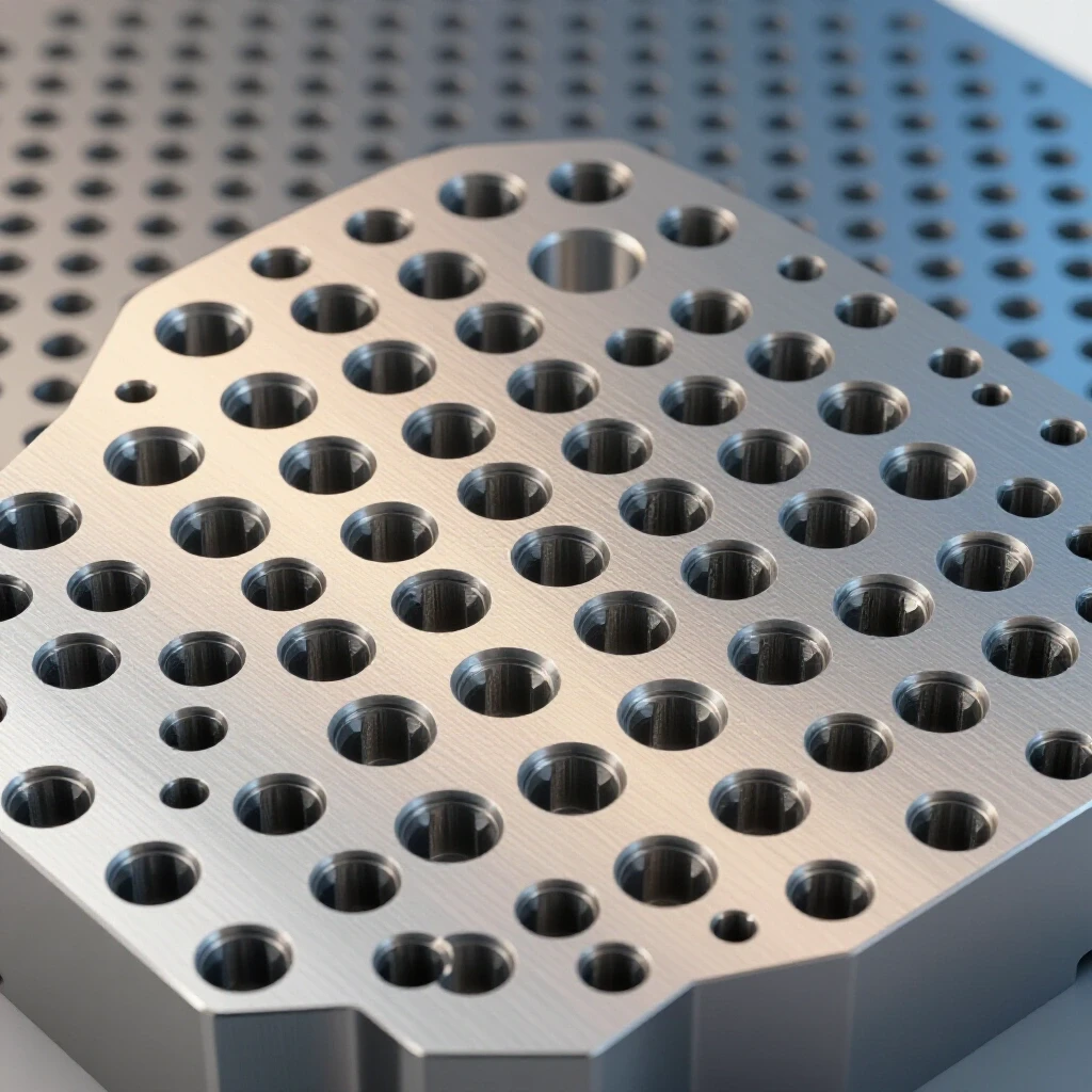
When you are drilling a row of holes, the distance between them is just as important as the distance to the edge. If holes are too close together, you create a “perforation” effect, much like a sheet of stamps. This makes the steel prone to a “zipper failure,” where a crack travels from one hole to the next until the entire joint separates.
The standard rule for hole-to-hole spacing is “3x the diameter.” If you have 1/2-inch bolts, the centers of those holes should be at least 1.5 inches apart. This ensures there is enough solid metal between the holes to distribute the load effectively. In my 14 years of work, I have found that sticking to this 3x rule virtually eliminates the risk of mid-plate cracking.
The Role of Material Thickness
While we often focus on the diameter of the hole, the thickness of the steel plate plays a massive role in how the edge behaves. A very thin plate will buckle or “curl” at the edge before it actually tears. A very thick plate is more resistant to curling but can be more prone to brittle fracture if the steel is of a lower grade.
If you are working with material thinner than 1/8 of an inch, the 1.5x rule might not be enough if the joint is under high tension. In these cases, I often use a “doubler plate.” This is a second piece of steel welded over the hole area to effectively double the thickness. This reinforces the edge and provides much more surface area for the bolt to bear against, which is a great trick for garage fabrication safety when you are limited by the materials you have on hand.
Integrating Welding and Fastening
Often, a project requires both welding and bolting. It is critical to remember that welding near a hole can cause distortion. If you weld a bracket and then try to bolt it, you might find that the heat has pulled the steel, moving your holes out of alignment.
I always prefer to do my heavy welding first, let the part cool completely, and then do my final layout and drilling. This ensures that the holes remain exactly where they need to be relative to the edges. If you must weld near an existing hole, keep your heat in check. Excessive heat can lead to welding defect troubleshooting issues like undercut or warping, which further weakens the area around your fasteners.
For those using MIG welding near these joints, remember to check your welding gas flow rate. I typically set mine between 15 and 20 CFH (cubic feet per hour). Proper gas coverage prevents porosity, which is a common internal weld defect. If you have porosity in a weld near a hole, you have essentially created a microscopic honeycomb of air pockets that will fail the moment the joint is stressed.
Final Inspection and Testing
Before I put any fabricated part into service, I perform a visual and physical inspection. I use a magnifying glass to look for tiny cracks around the edges of the holes. If I see anything suspicious, I use a simple dye penetrant kit. You spray a red dye on the area, wipe it off, and then apply a white developer. If there is a crack, the red dye will bleed through the white powder, making it clearly visible.
I also recommend a “dry fit” of all fasteners. If a bolt feels tight or you have to hammer it through, your holes are misaligned. Forcing a bolt creates “pre-stress” in the steel. This means the metal is already working hard before you even apply an external load. A safe, reliable structure should go together smoothly.
Practical Steps for Your Next Project
To ensure your projects are structurally sound, I suggest building a small “test coupon” when you are unsure. Take a scrap piece of the same steel you plan to use, drill a hole at your intended edge distance, and then try to destroy it. Put it in a vise and hit it with a sledgehammer or pull on it with a hydraulic jack. Seeing how the metal fails in a controlled environment is the best way to gain confidence in your design.
- Identify the maximum load your joint will carry.
- Select the appropriate bolt size (typically Grade 5 or Grade 8 for structural work).
- Calculate the 2x diameter distance for your hole centers.
- Clean the steel and perform a precise layout with a scribe and center punch.
- Drill a pilot hole, followed by the final size bit at a slow, steady RPM with cutting oil.
- Deburr the hole and the edge of the plate to remove sharp points where cracks can start.
- Inspect the final product for any signs of material distress.
By following these steps, you move away from guesswork and toward a data-driven approach to fabrication. It takes a little more time in the planning phase, but it saves an immense amount of time and money in the long run.
FAQ
What is the absolute minimum distance a hole can be from a steel edge? The absolute minimum is generally 1.5 times the diameter of the fastener. For example, a 1/2-inch bolt requires the center of the hole to be at least 3/4 of an inch from the edge. Going any closer significantly increases the risk of the metal tearing under load.
Does the type of steel change the edge distance requirements? For most common mild steels like A36, the 1.5x to 2x rules are standard. However, higher-strength steels or tempered steels may be more brittle, meaning they might require even more distance to prevent cracking. Always check the material properties if you are moving away from standard mild steel.
Can I weld a washer to the edge to strengthen a hole that is too close? While welding a washer can provide some surface area, it does not replace the strength of the base metal. If the hole is too close to the edge, the base metal can still tear underneath the washer. It is always better to redrill the hole in a safe location or use a larger reinforcement plate.
Is it better to drill or punch holes near an edge? Drilling is generally safer for structural integrity. Punching is a violent process that can create micro-fractures in the steel, especially near the edges. If you must punch holes, ensure the material is thick enough to resist the deformation that occurs during the process.
How does hole spacing change if I am using multiple rows of bolts? If you have multiple rows, you should maintain the 3x diameter spacing between holes in a row and also between the rows themselves. This ensures a uniform distribution of stress across the entire plate and prevents the “zipper” effect of multiple failures.
What should I do if I accidentally drill a hole too close to the edge? The safest course of action is to discard the piece or weld the hole completely shut using a high-quality welding process. After welding, grind it flush and redrill the hole at the correct distance. Do not try to “make it work” by using a smaller bolt or adding a shim.
How do I measure edge distance on a curved or irregular edge? On a curved edge, measure from the center of the hole to the nearest point on the boundary. The 1.5x rule still applies. If the curve is tight, you may want to increase the distance further, as the geometry can create additional stress concentrations.
Does using a Grade 8 bolt mean I can put the hole closer to the edge? No. A Grade 8 bolt is stronger than a Grade 5 bolt, but the steel plate itself has not changed. Using a stronger bolt actually increases the risk of tear-out because the bolt is less likely to fail, putting all the stress on the edge of the hole.
What is the impact of vibration on edge distance? Vibration causes “fatigue,” which can turn microscopic scratches into large cracks over time. If your project will be subject to constant vibration (like a vehicle bracket), I strongly recommend using a 2.5x or 3x diameter edge distance to provide a larger safety margin.
Should I use cutting oil when drilling near an edge? Yes, always use cutting oil. It reduces heat and friction, which prevents the steel from hardening or becoming brittle during the drilling process. A cool, clean cut is always structurally superior to one that was forced through dry.
(This article was written by one of our staff writers, James Harlan. Visit our Meet the Team page to learn more about the author and their expertise.)