How to Select the Right Flap Disc Grit for Steel (Review)
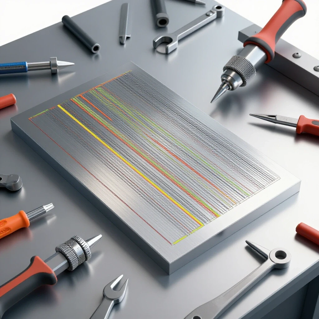
In my fourteen years of navigating the shop floor, I have learned that the most dangerous tool in a fabricator’s arsenal is not a malfunctioning saw or a high-voltage welder. It is often the subtle, overlooked choice of surface preparation. Early in my career, I was tasked with inspecting a heavy-duty equipment rack that had failed during a stress test. On the surface, the welds looked clean, but a macro-etch test revealed deep, jagged gouges beneath the weld toe. The fabricator had used an overly aggressive abrasive to clean the mill scale, creating “stress risers” that acted like pre-cut perforated lines in the steel. When the load hit 80% of its rated capacity, the metal simply unzipped along those scratches.
This experience fundamentally changed how I view the relationship between abrasive selection and structural integrity. For those of us working in home shops or small fabrication businesses, the stakes are high. We are often building trailers, structural frames, or load-bearing brackets where a failure isn’t just a nuisance—it is a liability. Choosing the correct abrasive particle size is not just about aesthetics; it is a critical engineering decision that affects the fatigue life and load capacity of your project.
Understanding the Physics of Abrasive Particle Sizing on Steel
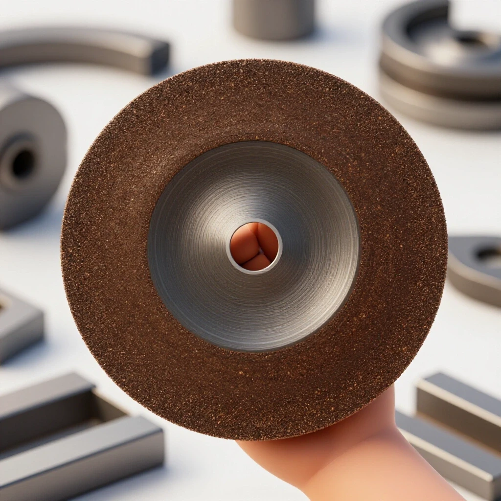
Abrasive particle sizing refers to the physical dimensions of the grains bonded to a flap disc, which dictates how deeply they penetrate the steel surface and how much material they remove per pass. In technical terms, grit size is determined by the number of openings per linear inch in a sizing screen; higher numbers indicate smaller particles.
When you press a spinning disc against a steel workpiece, you are performing micro-machining. A 36-grit particle acts like a tiny plow, carving deep furrows into the carbon steel. An 80-grit particle acts more like a fine chisel. Understanding this helps you manage the “surface profile,” which is the measured depth of the peaks and valleys on the metal. For structural steel like A36, which has a yield strength of roughly 36,000 PSI, an incorrect surface profile can reduce the effective cross-sectional area of the material, leading to premature failure under cyclic loading.
The Role of Surface Roughness in Structural Integrity
Surface roughness is the measurement of the texture of a metal surface, often expressed as Ra (Roughness Average). In structural fabrication, a surface that is too rough can harbor microscopic cracks, while a surface that is too smooth might not allow for proper paint or coating adhesion.
If you are preparing a joint for a critical weld, the goal is to remove contaminants without thinning the base metal. I have seen hobbyists take a 40-grit disc to 11-gauge (1/8 inch) tubing and accidentally grind away 10% of the wall thickness just trying to remove mill scale. In a structure designed with a 2:1 safety factor, you have just compromised your margin of error significantly.
Matching Abrasive Coarseness to Fabrication Stages
Every fabrication project follows a sequence: preparation, welding, and finishing. Using the same abrasive for all three stages is a common mistake that leads to poor weld quality and structural weakness.
Initial Material Cleaning and Mill Scale Removal
Mill scale is the flaky, bluish-black layer of iron oxide that forms on hot-rolled steel. It is brittle and has a higher melting point than the underlying steel. If you weld over it, you risk weld porosity and lack of fusion. For this stage, you need an abrasive that can bite through the oxide layer without gouging the base metal.
- Recommended Grit: 36 to 40
- Primary Goal: Rapid stock removal and cleaning.
- Risk: Over-grinding can create deep scratches that lead to “brittle fracture” points.
Weld Blending and Reinforcement Reduction
Once a weld is complete, you may need to level the “crown” or reinforcement of the weld to make it flush with the base metal. This is a delicate process. If you use a grit that is too coarse, you will leave deep scratches in the Heat Affected Zone (HAZ), which is the area of metal that didn’t melt but had its microstructure altered by the heat.
- Recommended Grit: 60
- Primary Goal: Leveling the weld bead while maintaining a consistent surface.
- Risk: Removing too much weld reinforcement can weaken the joint’s load capacity.
Final Surface Refining and Paint Preparation
The final stage involves removing the scratches left by previous steps to create a uniform finish. This is especially important if the part will be powder-coated or painted, as these coatings can highlight surface defects rather than hide them.
- Recommended Grit: 80 to 120
- Primary Goal: Smoothing and polishing.
- Risk: Spending too much time in one spot can generate excessive heat, leading to material warping.
| Fabrication Stage | Recommended Grit | Material Removal Rate | Surface Finish Quality |
|---|---|---|---|
| Mill Scale Removal | 36 – 40 | High | Rough / Jagged |
| Weld Blending | 60 | Medium | Uniform / Satin |
| Final Smoothing | 80 | Low | Smooth / Polished |
| Paint Prep | 120 | Very Low | Mirror-like / Fine |
Managing Heat-Affected Zone Weakness During Finishing
The Heat Affected Zone (HAZ) is the area surrounding a weld that has been subjected to high temperatures. This heat changes the grain structure of the steel, often making it more brittle or reducing its tensile strength. When you use a flap disc on this area, you are adding more friction-based heat.
I always tell my students to monitor the color of the steel. If the metal turns a deep blue or purple while you are grinding, you are reaching temperatures between 500°F and 600°F. While this isn’t enough to melt the steel, it can cause localized expansion and contraction, leading to “welding distortion” or warping. In a precision-aligned frame, even a 1/16-inch warp can throw the entire assembly out of square.
Strategies to Minimize Heat Buildup
- Use a “Light Touch”: Let the abrasive do the work. Pressing harder only increases friction and heat without significantly increasing the rate of material removal.
- Keep the Disc Moving: Never dwell in one spot for more than a second or two. Use long, sweeping strokes.
- Select the Right Backing: Rigid backings provide more pressure for heavy removal, while flexible backings dissipate heat better on contoured surfaces.
Selecting Particle Density for Structural Safety
The density of the abrasive flaps on a disc also plays a role in how the tool interacts with the steel. High-density discs have more flaps, which allows them to last longer and provide a softer “cushion” during grinding. For a risk-averse fabricator, high-density discs are often a safer choice because they are less likely to “dig in” and create the accidental gouges that lead to structural failure.
When I am inspecting a structural joint, I look for “undercutting.” This is a welding defect where the base metal is melted away at the toe of the weld, but it can also be caused by improper grinding. If you use a low-density, coarse-grit disc at a high angle, you can easily create a groove next to the weld. This groove becomes a focal point for stress, significantly lowering the structural metal load capacity.
Workshop Safety and Diagnostic Inspection Protocols
Before you even touch a disc to metal, your workshop safety checklist must be complete. Grinding produces high-velocity sparks and fine metallic dust. In my shop, I’ve seen a near-miss where a spark landed in a pile of oily rags ten feet away, smoldering for twenty minutes before igniting.
The Grinding Safety Zone
- Clearance: Ensure a 10-foot radius clear of flammable materials.
- Ventilation: Use a localized exhaust or a high-volume fan to move metallic dust away from your breathing zone.
- Shielding: If others are working in the shop, use welding screens to block the path of sparks.
PPE for Abrasive Work
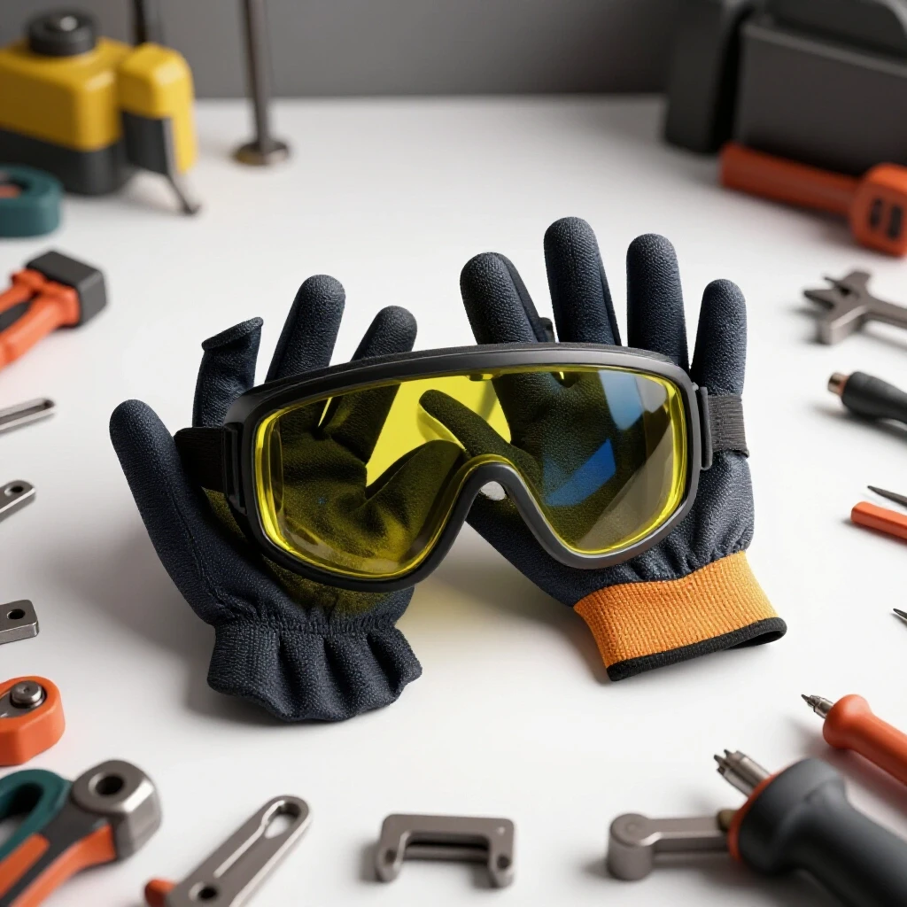
Standard safety glasses are often insufficient for the volume of debris generated by flap discs. I recommend a “double-up” approach: – Primary: Z87+ rated safety glasses with side shields. – Secondary: A full-face shield worn over the glasses. – Respiratory: A P100 rated particulate respirator to prevent “metal fume fever” and long-term lung damage from inhaling iron oxide dust.
Step-by-Step Guide to Preparing a Structural Joint
To ensure a project is structurally sound, follow this protocol for every load-bearing joint. This method minimizes the risk of internal weld defects and ensures the material maintains its rated strength.
- Initial Cleaning: Use a 40-grit disc to remove all mill scale, rust, and oil within two inches of the weld zone. Ensure you can see the “bright metal.”
- Beveling: For steel thicker than 3/16 inch, use a 36-grit disc to create a 30-to-45-degree bevel on the edges. This allows for full-depth weld penetration.
- Inspection: Look for deep scratches. If you see gouges deeper than 0.010 inches, smooth them out with a 60-grit disc before welding.
- Welding: Execute the weld using your calibrated settings (e.g., 15–20 CFH for shielding gas).
- Post-Weld Blending: Use a 60-grit disc to remove slag and level the weld. Do not grind the weld perfectly flush unless the design specifically requires it; leaving a slight “hump” provides a safety margin in the joint’s strength.
- Final Inspection: Use a magnifying glass or a dye-penetrant kit to check for surface cracks.
Case Study: The Failure of a Custom Utility Trailer Tongue
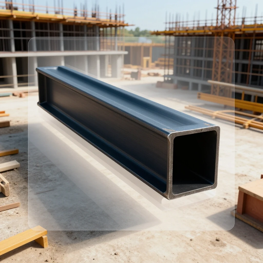
A few years ago, a neighbor asked me to look at a trailer tongue that had snapped while he was hauling a load of gravel. The trailer was made of 3-inch C-channel steel. Upon inspection, I found that the break occurred exactly where he had ground down a weld seam.
He had used a very coarse 36-grit disc to blend the weld but had been too aggressive. He had thinned the C-channel from 0.170 inches down to 0.120 inches in that specific spot. Furthermore, the deep scratches from the 36-grit abrasive were perpendicular to the direction of the load. This created a “zipper effect.” Under the bouncing load of the gravel, the stress concentrated in those scratches, causing a fatigue crack that eventually led to a total structural failure.
The fix would have been simple: use a 60-grit disc for blending and stop as soon as the weld was level with the surface, ensuring the grinding marks ran parallel to the direction of the stress, not across it.
Common Mistakes in Abrasive Selection
- Using a Worn-Out Disc: As the abrasive grains break down, the disc stops cutting and starts rubbing. This generates immense heat without removing material, which can ruin the temper of the steel.
- Ignoring the RPM Rating: Every disc has a maximum RPM. Exceeding this is a major safety risk. If a disc shatters at 11,000 RPM, the fragments travel at over 200 miles per hour.
- Grinding with the Edge: Flap discs are designed to be used at a shallow angle (5 to 15 degrees). Using the very edge of the disc increases the risk of “digging in” and creating structural weak points.
Structural Verification Checklist
Before considering a project finished, go through this checklist to ensure your abrasive work hasn’t compromised the build.
- Wall Thickness Check: Use calipers to verify that the steel thickness near ground joints is within 95% of its original dimension.
- Visual Inspection: Check for “blueing” of the metal, indicating excessive heat.
- Surface Profile: Ensure there are no deep, sharp-bottomed scratches in high-stress areas.
- Weld Profile: Verify that the weld still has a slight convex shape (unless a flush fit is required).
- Cleanliness: Ensure all abrasive dust is removed before applying any protective coatings.
Advanced Diagnostic Tools for the Home Shop
While professional labs use X-rays, you can use more accessible tools to verify your work. – Dye Penetrant Kits: These consist of a cleaner, a red dye, and a developer. The dye seeps into any surface cracks that are invisible to the naked eye, making them turn bright red. – Magnetic Particle Inspection: A simple magnet and some iron filings can help reveal sub-surface cracks in carbon steel. – Digital Calipers: Essential for monitoring material removal and ensuring you haven’t thinned out critical structural members.
Conclusion
Mastering the use of abrasives is a journey from focusing on how a project looks to focusing on how it performs. By selecting the right particle size for each stage of the process, you protect the structural integrity of your steel and ensure the safety of those who will use your creations. Remember that every scratch you put into the metal is a potential failure point. Treat the surface of your steel with the same respect you give your welding arc or your structural calculations.
Next Steps for the Risk-Averse Fabricator
- Audit Your Inventory: Check your current stock of discs. Do you have a range from 40 to 120 grit, or are you trying to make one size do everything?
- Practice Heat Management: Take a scrap piece of steel and intentionally try to “blue” it with a coarse disc. This will help you recognize the warning signs of overheating.
- Implement a Checklist: Print out a workshop safety checklist and a joint verification list to keep at your workbench.
- Focus on Direction: Practice grinding so that your finish marks run parallel to the expected load of the part, which helps minimize stress concentration.
FAQ: Abrasive Selection and Structural Safety
Why shouldn’t I use a 36-grit disc for everything if it works the fastest? While 36-grit removes material quickly, it leaves deep “V-shaped” scratches in the steel. In structural engineering, these are known as stress risers. Under load, these scratches act as starting points for cracks. For structural safety, you should always follow up a coarse grit with a finer grit (like 60 or 80) to “round out” the bottoms of those scratches and reduce the risk of fatigue failure.
How do I know if I’ve ground away too much metal? The best way is to use digital calipers to measure the thickness of the steel before and after grinding. In structural applications, you generally want to avoid removing more than 5% of the base metal’s thickness. If you started with 0.125-inch material and you’re now at 0.110-inch, you have significantly reduced the structural load capacity of that component.
Can the heat from a flap disc actually weaken the steel? Yes. Carbon steel has a specific grain structure created during its manufacturing. Excessive heat from grinding (indicated by the metal turning blue or purple) can “anneal” or soften the steel in a localized area. This creates a weak spot in your frame that may bend or fail long before the rest of the structure reaches its limit.
Does the angle of the grinder matter for structural integrity? Absolutely. Using a flap disc at a steep angle (over 20 degrees) concentrates all the pressure on a small area, making it very easy to “undercut” the metal or gouge a deep groove. Keeping a shallow angle (5-15 degrees) distributes the pressure and creates a smoother transition between the weld and the base metal.
Is it better to leave the mill scale on if I’m worried about thinning the metal? No. Mill scale is an insulator and a contaminant. If you weld over it, the arc will be unstable, and the weld will likely have “porosity” (tiny holes) or “lack of fusion” (where the weld just sits on top of the scale instead of bonding to the steel). You must remove the scale, but do it carefully with a 40 or 60 grit disc rather than a heavy grinding wheel.
What is the “Heat Affected Zone” (HAZ) and why is it so sensitive? The HAZ is the area of the base metal that was heated during welding but didn’t melt. This area often becomes the “weakest link” in a joint because the heat can make the grain structure larger and more brittle. When grinding in the HAZ, you must be extra careful not to add more heat or create deep scratches, as this is where most structural cracks begin.
How can I tell the difference between a 60-grit and an 80-grit finish? A 60-grit finish will have a visible “brushed” look with distinct lines, similar to a heavy-duty kitchen appliance. An 80-grit finish will look much smoother and will start to reflect light more uniformly. If you run your fingernail across the surface, you will feel the ridges on a 60-grit finish, whereas an 80-grit finish will feel almost flat.
Do I need different discs for different types of steel? This guide focuses on carbon and structural steel. While the grit sizes remain similar, the “chemistry” of the abrasive can vary. For standard steel, zirconia or ceramic alumina grains are preferred because they “self-sharpen” as they break down, providing a consistent cut and generating less heat than cheaper aluminum oxide discs.
What is the most common mistake when blending welds? The most common mistake is trying to make the weld perfectly invisible. While a flush weld looks great, the “reinforcement” (the part of the weld that sticks up) actually provides extra strength. For structural projects, it is often safer to leave a small amount of reinforcement and just smooth the edges where the weld meets the base metal to avoid stress concentrations.
How often should I replace my flap disc? Replace the disc as soon as you notice you have to apply more pressure to get the same result. A “glazed” or worn disc generates much more heat and increases the risk of slipping or gouging the metal. From a safety perspective, a fresh disc is always more predictable and easier to control.
(This article was written by one of our staff writers, James Harlan. Visit our Meet the Team page to learn more about the author and their expertise.)