How to Align Drilled Holes Accurately in Steel Parts (Fix)
I have spent over 14 years on the shop floor, often standing over a drill press or a workbench, trying to solve the puzzle of two steel plates that simply refuse to line up. In my early years as a mechanical engineer and fabricator, I assumed that if I measured twice and marked once, the bolts would slide through like butter. I was wrong. I quickly learned that steel is a stubborn medium; it moves, it resists, and it punishes even a half-millimeter of error. When a structural frame doesn’t bolt together because the holes are off by the thickness of a fingernail, you don’t just lose time—you lose the structural integrity of the entire project.
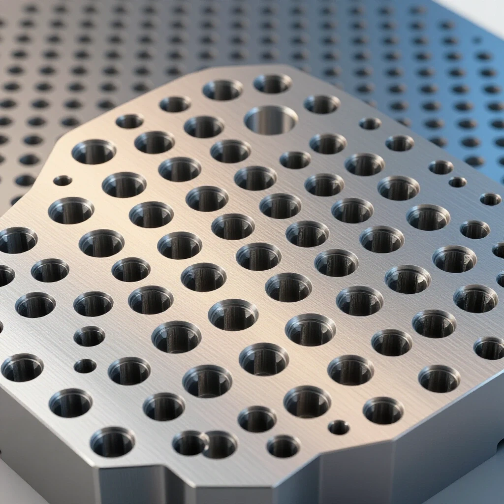
My background in industrial inspection taught me that a misaligned hole is more than just an annoyance. It creates uneven loading on fasteners, which can lead to premature wear or even a catastrophic shear failure under load. In this guide, I will share the hard-won lessons from my workshop, focusing on manual techniques to ensure your fasteners fit exactly where they should. We will look at how to transfer marks accurately, the importance of rigid fixturing, and how to correct those inevitable small errors without compromising the strength of your steel parts.
The Physics of Hole Misalignment in Structural Steel
Achieving concentricity—where the centers of two holes in separate parts align perfectly—is the primary goal of any mechanical assembly. In steel fabrication, even a small deviation can prevent a bolt from passing through or cause it to bind, creating unintended stress points in the material.
When we talk about alignment, we are managing tolerances. For most manual workshop projects involving steel plate up to 12 mm thick, we aim for a tolerance of 0.1 mm to 0.3 mm. If your holes are outside this range, you will likely struggle with assembly. Steel does not have the “give” that wood or plastic offers. If a 10 mm bolt needs to pass through a 10.5 mm hole, and that hole is offset by 1 mm, the bolt simply will not fit. This creates a “bind” where the fastener applies lateral pressure to the side of the hole, reducing the effective clamping force and potentially leading to joint failure over time.
Understanding Mechanical Load Paths and Fastener Fit
A load path is the route that physical force takes through a structure. In a bolted steel joint, the load should ideally be distributed evenly across the shank of the bolt and the internal walls of the drilled holes.
When holes are misaligned, the bolt may only contact a small portion of the hole’s surface area. This concentrates the force, exceeding the local yield strength of the steel. For common A36 mild steel, the yield strength is approximately 36,000 PSI. If all the weight of a structure is resting on a tiny sliver of misaligned steel, that point can deform or “egg out,” leading to a loose joint. To prevent this, we must ensure that our drilling process accounts for the thickness of the material and the tendency of drill bits to “walk” or wander across the surface.
- Yield Strength: The point at which steel permanently deforms.
- Shear Stress: The force tending to cause deformation of a material by slippage along a plane or planes parallel to the imposed stress.
- Safety Factor: A ratio of the breaking strength of a part to the actual load it is expected to carry (typically 3:1 or 5:1 for hobbyist structures).
Mechanical Transfer Methods for High-Precision Layout
The most common cause of misalignment is trying to measure and mark two different parts independently. Even with a high-quality steel rule, human error in reading the scale or placing the scribe mark can lead to a 0.5 mm discrepancy.
Instead of measuring twice, I prefer the “master part” method. This involves drilling one part perfectly and then using it as a physical template to mark the second part. This ensures that the relative distance between holes remains identical across both pieces. To do this accurately, you need a set of transfer punches. These are hardened steel pins with a point ground exactly in the center of the diameter. By placing the punch through the existing hole of your master part and giving it a light tap with a hammer, you create a perfectly centered dimple on the workpiece below.
Steps for Using Transfer Punches Effectively
- Deburr the Master Hole: Ensure the underside of your first drilled part is completely flat. Any burr or “volcano” of metal around the hole will tilt the part and ruin the alignment.
- Clamp the Parts: Use heavy C-clamps or F-clamps to lock the two plates together. If they move even a fraction of a millimeter during marking, the alignment is lost.
- Select the Correct Punch Size: The punch must fit snugly in the hole with no side-to-side play. If the hole is 10 mm, use a 10 mm transfer punch.
- Mark with a Single Tap: One sharp blow is better than several light ones, which can cause the punch to bounce and create a “double dimple.”
| Tool Type | Purpose | Expected Accuracy |
|---|---|---|
| Steel Rule & Scribe | Manual measuring and marking | +/- 0.5 mm |
| Transfer Punch | Copying hole locations from a template | +/- 0.1 mm |
| Center Punch | Deepening a mark for a drill bit | +/- 0.2 mm |
| Optical Center Punch | High-precision visual centering | +/- 0.05 mm |
Fixturing and Clamping for Concentricity
A common mistake I see in many workshops is holding the workpiece by hand or using inadequate clamping while drilling. Steel is a dense material, and as the drill bit cuts, it generates significant torque. If the part shifts even slightly, the hole will be angled or offset.
Proper fixturing involves more than just holding the part down; it involves “locating” the part so it cannot move in any direction. For stacked plates, I often use “dead holes” or “tack-drilling.” This means I clamp the plates together, drill a single hole through both, and immediately insert a tight-fitting bolt or a dowel pin through that hole. This bolt now acts as a secondary clamp, preventing the plates from pivoting while I drill the remaining holes.
Workshop Safety Checklist for Drilling Operations
- Secure the Workpiece: Never hold a steel part by hand while drilling. Use a drill press vise or clamps bolted to the table.
- Check Drill Speed: For mild steel, use slower speeds (RPM) as the drill diameter increases. High speeds cause heat buildup and bit wandering.
- Use Cutting Fluid: This reduces friction and prevents the bit from grabbing the metal, which can jerk the workpiece out of alignment.
- Clear the Chips: Long, stringy steel shavings can wrap around the bit and pull the part out of position. Stop frequently to clear debris.
Corrective Reaming and Adjustment Techniques
Even with the best preparation, you might find that your holes are off by a fraction of a millimeter. When this happens, do not reach for a larger drill bit. A drill bit is designed to cut a new hole, not to enlarge an existing one slightly to one side. If you try to “steer” a drill bit, it will often chatter, create an oval hole, or snap.
The professional fix for minor misalignment is a bridge reamer or a construction reamer. Unlike a drill bit, a reamer has multiple flutes and is designed to shave away very small amounts of material (0.1 mm to 0.5 mm) to bring two holes into perfect alignment. If a bolt is sticking, I use a reamer to gently open the passage. This maintains the circular integrity of the hole and ensures the bolt has maximum surface contact with the steel.
How to Fix an Out-of-Alignment Hole
- Identify the High Spot: Use a flashlight to look through the stacked holes and see which way the bottom plate needs to move.
- Select a Reamer: Choose a reamer that matches your final bolt size.
- Apply Constant Pressure: Use a low-speed drill or a hand wrench to turn the reamer. The multiple flutes will shave the “crescent” of metal that is blocking the bolt.
- Verify with a Dowel: Instead of forcing the bolt, use a smooth dowel pin to check for a “slip fit.” If the dowel slides through, the bolt will too.
Structural Load Capacities and Joint Integrity
When we modify holes by reaming or enlarging them, we must consider the structural safety margins. A hole that is too large for the bolt (excessive clearance) reduces the bearing area. In a structural joint, we generally want the hole to be no more than 1.5 mm larger than the bolt diameter for standard applications.
If you find you have to enlarge a hole significantly to get parts to fit, you are effectively reducing the amount of steel available to resist the load. This is where the concept of “edge distance” becomes critical. Industry standards usually suggest that the center of a hole should be at least 1.5 to 2 times the bolt diameter away from the edge of the plate. If your alignment error forces you to move a hole closer to the edge, you risk a “tear-out” failure where the bolt literally rips through the side of the steel plate under tension.
- Standard Bolt Clearance: 0.5 mm to 1.0 mm over bolt diameter.
- Oversized Hole Limit: Avoid exceeding 3.0 mm over bolt diameter without engineering review.
- Bearing Strength: The ability of the steel surrounding the hole to resist the crushing force of the bolt.
Practical Tools for Precision Alignment
To achieve professional results in a home shop, you don’t need expensive machinery, but you do need the right manual tools. I keep a dedicated “alignment kit” in my drawer that has saved countless projects from the scrap bin.
- Transfer Punch Set: A full set from 1 mm to 13 mm covers almost all common bolt sizes.
- Drill Drift or Taper Pins: These are tapered steel pins you can drive into a misaligned hole to “pull” the plates into position before clamping.
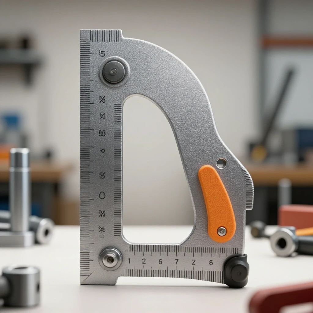
- Machinist’s Square: Essential for ensuring your drill press table is 90 degrees to the spindle. An angled hole is a misaligned hole.
- Calipers: A set of digital or dial calipers allows you to measure the exact distance between hole edges to verify your layout before you ever start the drill.
- Step Drills: For thinner plates (under 5 mm), step drills are less likely to wander than standard twist drills.
Managing Material Thickness and Drill Wander
When drilling through 10 mm or 12 mm steel, the length of the drill bit becomes a factor. Long bits are flexible. If the tip hits a hard spot in the steel or if the starting dimple isn’t deep enough, the bit will flex. By the time it exits the bottom of a thick plate, it may be 1 mm or more away from the entry point.
To prevent this “drill wander,” I always start with a center drill. These are short, stubby bits that are extremely rigid. They create a shallow, precise pilot hole that guides the larger twist drill. For holes over 8 mm, I also drill a small pilot hole first (around 3 mm). This pilot hole reduces the “web force” required to push the larger bit through the metal, which keeps the drill running straighter and reduces the heat generated in the heat-affected zone of the cut.
Alignment Verification Checklist
- [ ] Is the drill press table square to the bit?
- [ ] Are the workpieces clamped so they cannot rotate or lift?
- [ ] Did I use a center drill to start the hole?
- [ ] Is the transfer punch the exact same size as the master hole?
- [ ] Have I cleared all burrs from between the mating surfaces?
- [ ] Am I using the correct RPM and lubricant for the steel thickness?
Conclusion: Building with Confidence
Aligning holes in steel is a test of patience and process. In my 14 years of fabrication, I’ve found that the most successful projects aren’t the ones where everything went perfectly, but the ones where the fabricator took the time to verify every step. By using mechanical transfer methods like punches, ensuring rigid fixturing, and having the tools on hand to correct minor deviations, you can build structures that are both safe and professional.
Remember that steel doesn’t forgive mistakes, but it does reward precision. Take that extra five minutes to clamp your work and check your layout. The reward is a project that bolts together effortlessly, with the peace of mind that every fastener is doing its job exactly as designed.
Frequently Asked Questions
What should I do if my drill bit starts to “walk” away from my mark?
If the bit wanders, stop immediately. Do not try to force it back. The best fix is to use a small round file to create a new “center” in the direction the hole needs to go, or use a center punch to create a deeper, corrected dimple. Then, restart with a smaller pilot bit.
How much larger should my hole be than my bolt?
For general fabrication, a “standard fit” is usually 0.5 mm to 1.0 mm larger than the bolt diameter. For example, use a 10.5 mm or 11 mm drill bit for a 10 mm bolt. This provides a small amount of “clearance” to account for minor manufacturing variations without sacrificing joint strength.
Can I use a hand drill for accurate hole alignment?
It is difficult but possible. To succeed, you must use a center punch and a pilot bit. However, a hand drill often results in “angled” holes, which will cause misalignment when stacking plates. A drill press is always the preferred tool for ensuring the hole is perfectly perpendicular to the plate surface.
Why do my holes line up on the top but not on the bottom?
This is usually caused by “drill wander” or an un-squared drill press table. If the drill bit is not perfectly 90 degrees to the workpiece, it will travel diagonally through the metal. As the plate gets thicker (e.g., 12 mm), this exit error becomes more pronounced.
Is it safe to “slot” a hole with a file to make a bolt fit?
Yes, for many non-critical applications, slightly elongating a hole with a file is a standard practice. However, ensure you are not filing toward the edge of the plate, as this reduces the “edge distance” and can weaken the joint. Always try to keep the slot as small as possible.
What is the best way to align holes in two pieces of angle iron?
Clamp the two pieces of angle iron together “nested” or back-to-back. Drill through both pieces at the same time. This is the only way to ensure that the hole spacing is identical on both components.
How do I prevent burrs from pushing my plates apart?
When drilling through stacked plates, the “chips” can sometimes get forced between the two layers, creating a gap. To prevent this, clamp the plates very tightly. If a gap forms, stop, unclamp, clean the debris, and re-clamp before continuing.
What tool should I use if the holes are off by only 0.2 mm?
A bridge reamer is the best tool for this. It will shave the interfering edge of the metal smoothly. If you don’t have a reamer, a round “chainsaw” file can work for small adjustments, though it is less precise.
Does the thickness of the steel affect how I should mark my holes?
Yes. In thicker steel (10 mm+), your layout marks must be very deep because the drill bit will be under more pressure and is more likely to slip out of a shallow mark. Use a heavy hammer blow on your center punch for thicker sections.
Can I use a bolt as a transfer punch?
I don’t recommend it. Bolts have flat or slightly concave ends and are not hardened for marking. They will not create a centered or crisp enough dimple for a drill bit to follow. Investing in a proper set of hardened transfer punches is essential for accuracy.
(This article was written by one of our staff writers, James Harlan. Visit our Meet the Team page to learn more about the author and their expertise.)