How to Improve Cut Line Visibility on Dark Steel Parts (Fix)
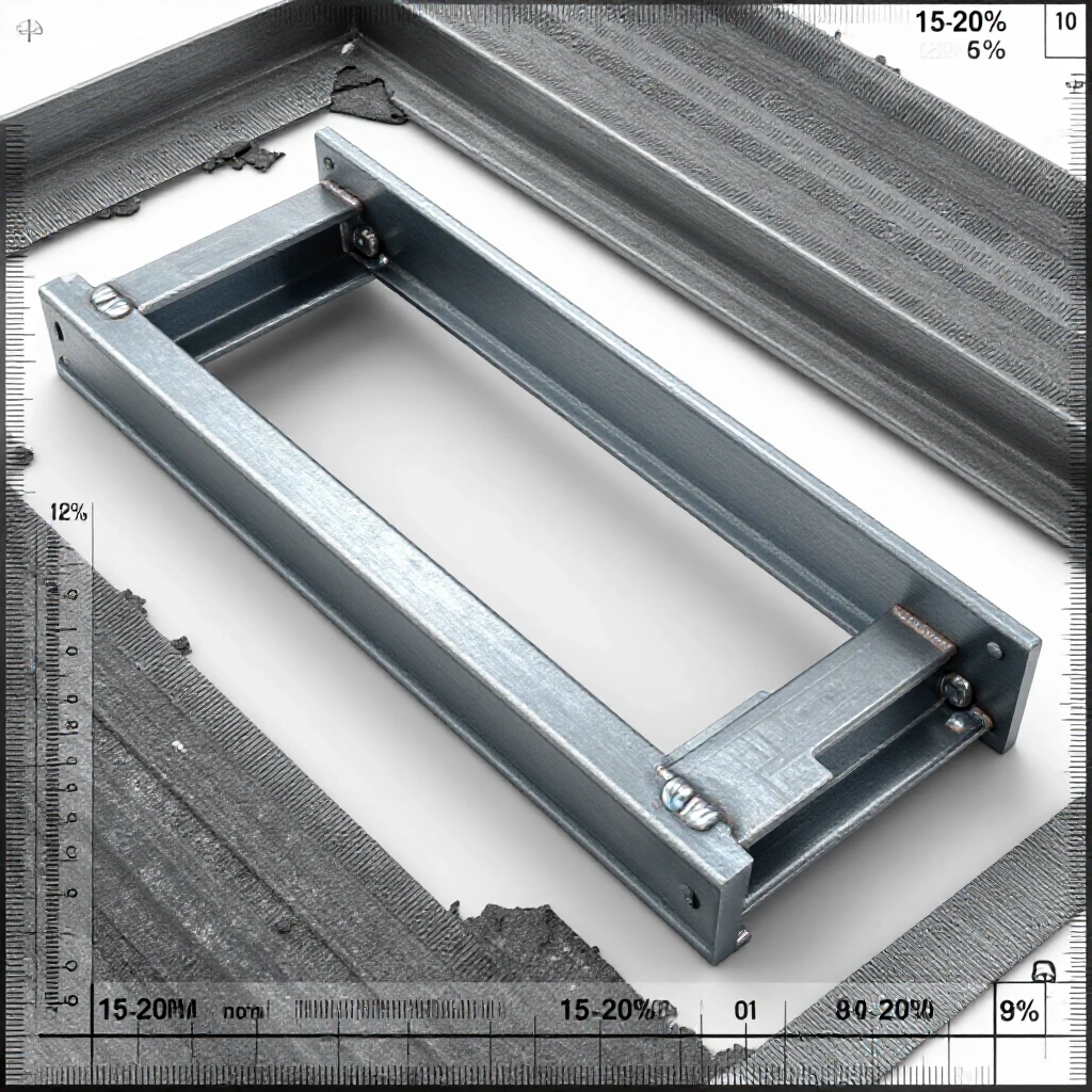
In my fourteen years on the shop floor, I have seen more structural failures caused by a simple pencil line than by complex engineering errors. When you are working with hot-rolled steel, the dark, flaky mill scale acts like a sponge for light, making your marks nearly invisible once the sparks start flying. I remember a specific project involving a heavy equipment trailer where a missed layout mark led to a three-degree misalignment in the main C-channel. It looked fine to the naked eye during fit-up, but under a load test, the uneven stress distribution caused a catastrophic weld failure. That incident taught me that precision begins long before the torch is lit; it starts with how clearly you can see your path.

Enhancing Surface Contrast for Accurate Layout
Layout fluids and specialized marking tools are the first line of defense against fabrication errors. These methods create a visual barrier between the dark steel surface and your intended cut path, ensuring that you aren’t guessing where the blade should land.
Using high-contrast layout fluids is a standard industrial practice for a reason. By applying a thin, quick-drying dye to the steel, you create a surface where a carbide scribe can bite through to reveal the bright, shiny metal underneath. This creates a “glow” effect under shop lights that a standard soapstone or carpenter’s pencil simply cannot match. For hobbyists and intermediate builders, moving away from thick, blunt markers toward precision scribing is the most effective way to reduce the margin of error in structural joints.
| Marking Method | Visibility Level | Precision (Inches) | Best Use Case |
|---|---|---|---|
| Standard Soapstone | Low | 1/16″ to 1/8″ | Rough cutting, general assembly |
| Silver Streak Pencil | Medium | 1/32″ | General fabrication, tube notching |
| Layout Dye & Scribe | High | 0.005″ | Critical fit-up, structural joints |
| White Paint Marker | Medium-High | 1/16″ | Plasma cutting, dark environments |
The Role of Directional Lighting in Scribe Line Clarity
The physics of how light hits a piece of dark steel determines whether you see a clear line or a blurry smudge. Proper lighting setup is not just about brightness; it is about the angle of incidence and how shadows interact with the physical grooves in the metal.
When you scribe a line into steel, you are creating a microscopic V-groove. If your shop lights are directly overhead, the light fills the groove and eliminates the shadow, making the line disappear. By using adjustable task lighting positioned at a low angle relative to the workpiece, you create a high-contrast shadow inside the scribe mark. I recommend using LED lamps with a high Color Rendering Index (CRI) to ensure the light doesn’t wash out the natural color of the steel or the layout fluid you have applied.
- Position the primary light source at a 30-degree angle to the work surface.
- Use a secondary “fill” light from the opposite side to eliminate harsh glares.
- Ensure the light source is shielded to prevent direct glare into your welding helmet or safety glasses.
- Clean the steel surface with a wire brush or solvent before lighting to remove reflective oils.
Mechanical Scribing Techniques for Permanent Paths
A mechanical scribe is a tool that physically displaces material rather than just depositing it on the surface. Understanding the difference between a surface mark and a physical groove is vital for maintaining accuracy during high-vibration cutting processes like bandsawing.
In my experience, many fabricators rely too heavily on soapstone, which can be wiped away or obscured by cooling fluids. A carbide-tipped scribe creates a permanent physical reference point that survives the heat-affected zone (HAZ) of a cut. When you are working on structural frames where a 1/16-inch gap can lead to excessive weld shrinkage and warping, the precision of a scribed line is your best insurance policy. This physical groove also provides a “track” that you can feel with your fingernail or a center punch, adding a tactile layer of verification to your visual checks.
- Carbide-Tipped Scribe: Best for fine, thin lines on layout dye.
- Automatic Center Punch: Used to “pop” marks along the scribe line for visibility under a welding hood.
- Silver Welders Pencil: Contains reflective lead that glows under the arc, perfect for following lines while welding.
- Dividers and Compasses: Essential for marking radii and consistent offsets on dark plate.
Why Layout Precision Prevents Structural Weld Defects
Poor visibility during the layout phase often leads to improper joint fit-up, which is a leading cause of internal weld defects. When parts do not align correctly because a cut line was misread, the resulting gaps require more filler metal and higher heat input.
Increasing the heat to bridge a wide gap expands the heat-affected zone (HAZ), which can weaken the base metal’s molecular structure. In structural applications, a large HAZ can lead to brittle failure or stress cracking over time. By ensuring your cut lines are highly visible and accurate, you achieve a “tight” fit-up. This allows for a consistent welding gas flow rate—typically 15–20 CFH—and ensures the shielding gas effectively protects the molten puddle from atmospheric contamination, which causes porosity.
| Fit-up Gap Size | Required Heat Input | Risk of Distortion | Structural Integrity |
|---|---|---|---|
| 0″ – 1/32″ | Low/Optimal | Minimal | High |
| 1/16″ | Medium | Moderate | Good |
| 1/8″ or larger | High | High | Potential for failure |
Workshop Safety Protocols for Visual Layout Work
Safety in the layout phase is often overlooked, but it is where many “close-call” incidents occur. Proper eye protection and ergonomic positioning are necessary to prevent fatigue, which is the primary driver of layout mistakes.
When you are leaning over a dark piece of steel trying to find a faint mark, you are at risk of eye strain and physical injury. OSHA standards emphasize the importance of adequate illumination in industrial workspaces to prevent such issues. I always insist on wearing clear safety glasses with an anti-reflective coating during the layout phase. If you are using a plasma cutter or torch to follow your lines, upgrading to a Shade 3 or Shade 5 cutting face shield will protect your eyes from infrared radiation while still allowing enough visible light to see your high-contrast marks.
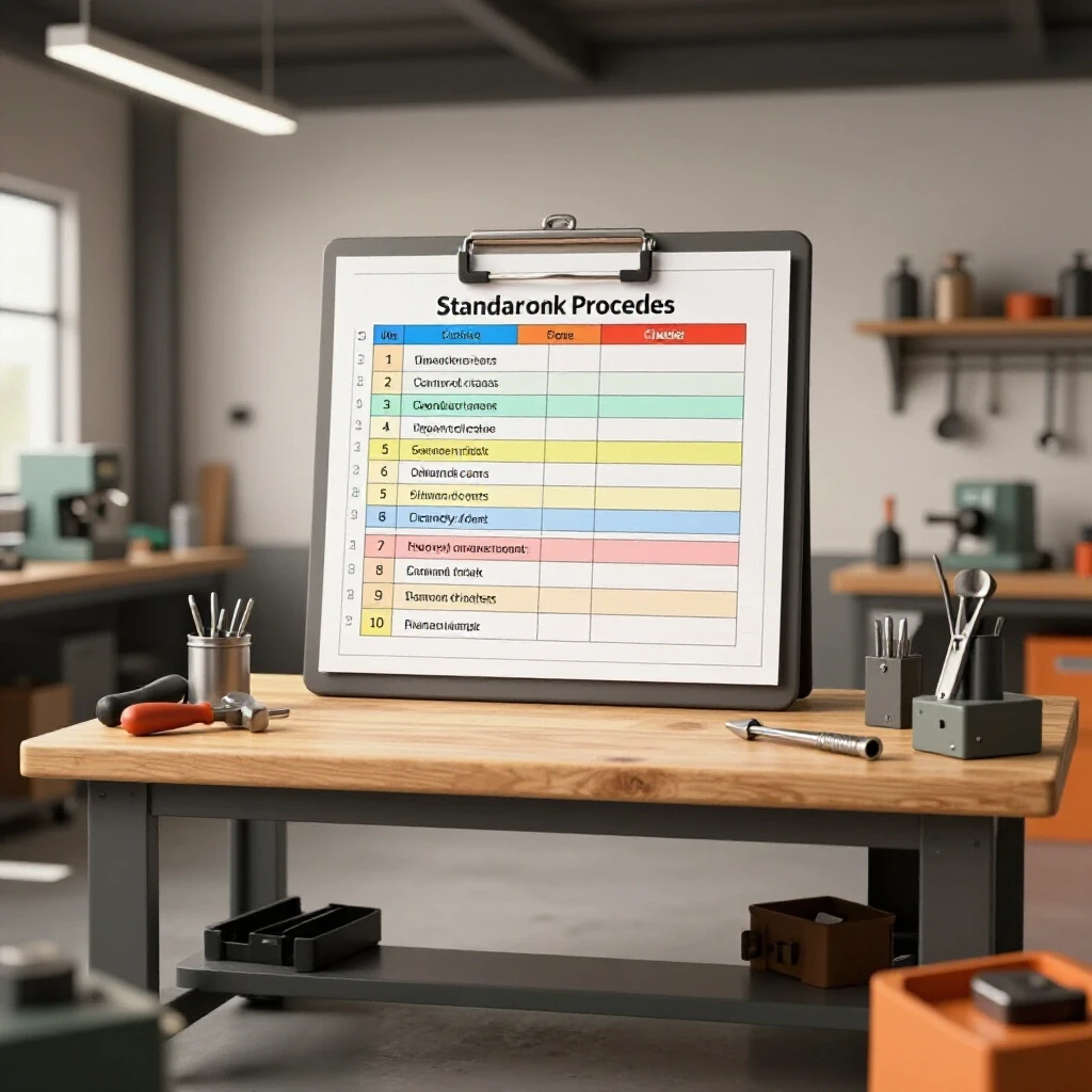
- Workshop Safety Checklist for Layout:
- Clear all trip hazards and scrap metal from the layout table.
- Verify that task lighting is secure and won’t fall during cutting.
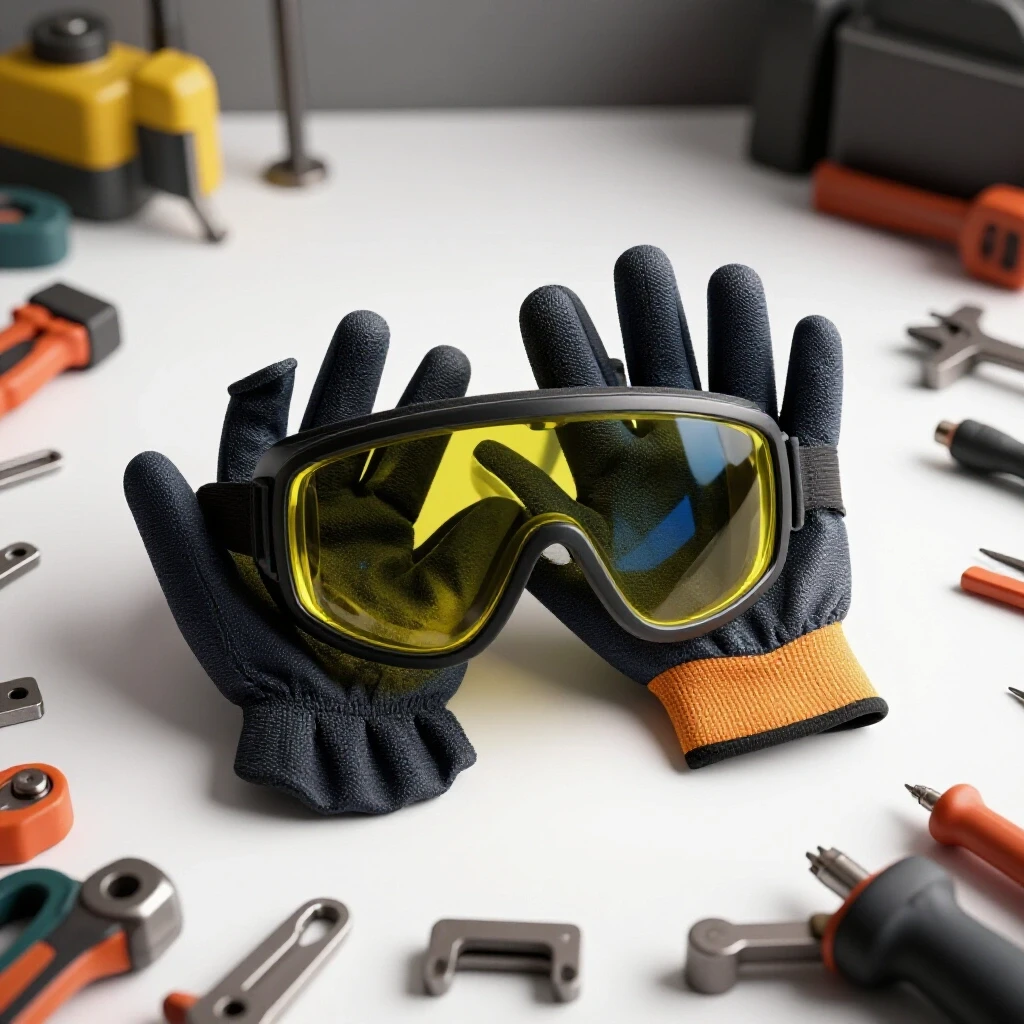
- Wear cut-resistant gloves when handling raw steel edges.
- Ensure adequate ventilation if using aerosol layout fluids or solvents.
- Check that your marking tools are sharp; a dull scribe leads to wider, less accurate lines.
Diagnostic Inspection of Cut Accuracy
Once a cut is completed, it must be inspected against the original layout to verify structural dimensions. This step is the final “fail-safe” before the parts are permanently joined by welding.
I use a combination of precision squares, calipers, and feeler gauges to verify that my cuts have stayed true to the high-visibility lines I created. If a cut has drifted, it is better to scrap the part or grind it back to square than to try and “fix it in the weld.” A weld can only be as strong as the joint preparation that precedes it. By treating the layout as a formal diagnostic process, you transition from a hobbyist mindset to a professional engineering approach, where every measurement is a data point in the safety of the final structure.
- Step 1: Deburr the cut edge using a file or flap disc to reveal the true edge.
- Step 2: Place a machinist square against the reference edge and check for light gaps.
- Step 3: Measure the total length using a calibrated tape measure or long-range calipers.
- Step 4: Document any deviations and determine if they fall within the allowable tolerance for the specific project.
Managing Heat and Distortion During the Cutting Process
The visibility of your line can change as the metal heats up during a cut. Thermal expansion can cause the steel to move, and the heat can burn off certain types of marking media.
If you are using a torch or plasma cutter, the intense light of the arc can wash out your marks entirely. This is why “punching” your line is so effective. By using a center punch to create a series of small indentations every half-inch along your scribe line, you create a “connect-the-dots” path that remains visible even when the metal is glowing red. This technique prevents “wandering” during long cuts, which is a common cause of wasted material and structural misalignment in large-scale projects like trailer frames or shop benches.
- Thermal Tip: Always cut on the “waste side” of your line.
- Cooling Tip: If using a bandsaw, ensure the coolant flow is directed to wash away chips but not the layout fluid.
- Stability Tip: Secure the workpiece with heavy-duty C-clamps to prevent movement during the layout and cutting phases.
Practical Benchmarks for Layout Success
To ensure your projects meet professional standards, you should aim for specific benchmarks during the preparation phase. These metrics help you quantify your progress and identify areas where your visibility or accuracy might be lacking.
A successful layout on dark steel should allow you to see the mark clearly from a distance of 24 inches under standard shop lighting. If you have to squint or use a flashlight, your contrast is insufficient. For structural projects, aim for a layout tolerance of +/- 1/32 of an inch. While this may seem strict for a hobbyist, it provides the necessary safety margin to account for the natural distortion that occurs during the welding process. By holding yourself to these benchmarks, you reduce the likelihood of structural fatigue points caused by poor joint geometry.
Frequently Asked Questions
Why does my soapstone disappear as soon as I start cutting? Soapstone is a soft mineral that easily powders and blows away under the pressure of a torch or the vibration of a saw. It also lacks the heat resistance to stay visible near the cutting path. Switching to a silver-lead pencil or a scribed line with layout dye provides a more durable mark that resists heat and physical displacement.
What is the best way to clean mill scale before marking? Mill scale is a layer of iron oxide that forms during the hot-rolling process. To get the best visibility, use a wire wheel or a light abrasive disc to remove the scale in the area where you plan to mark. This reveals the bright steel underneath, providing an immediate boost in contrast for any marking tool you choose.
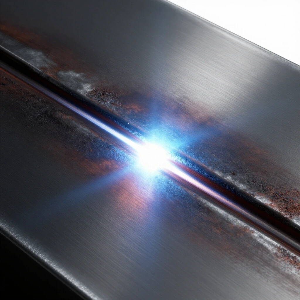
How do I see a scribe line through a welding helmet? When following a line while welding, use a “Silver Streak” pencil or a series of center punch marks. These reflect the light of the welding arc back to your eyes, allowing you to see the path through the darkened lens. Ensuring your helmet cover lens is clean and scratch-free is also vital for maintaining visibility.
Does the color of layout fluid matter? Blue is the industry standard because it provides the best contrast against the bright silver of a scribe mark. However, red layout fluid is often used on aluminum or stainless steel. For dark, hot-rolled steel, blue dye is almost always the superior choice for maximum visibility.
Can I use a standard permanent marker for structural layout? Standard permanent markers have a thick tip that creates a line roughly 1/16″ wide. This is often too imprecise for structural work where fit-up is critical. Additionally, the ink can sometimes interfere with weld quality if not fully removed, though this is less of a concern than the lack of precision.
How does lighting affect my accuracy on dark metal? Dark steel absorbs a significant amount of light. If your shop is dimly lit, your pupils will dilate, reducing your depth perception and making it harder to follow fine lines. High-intensity, angled task lighting is essential for creating the shadows needed to see physical scribe marks.
What safety gear do I need for layout work? At a minimum, you need Z87+ rated safety glasses. If you are using layout fluids, ensure you have adequate ventilation or a respirator rated for organic vapors. Cut-resistant gloves are also important when handling steel sheets or bars with sharp, mill-cut edges.
How do I prevent my marks from being rubbed off during handling? If you must use a pencil or marker, apply a quick coat of clear acrylic spray over the layout area. This “locks” the mark to the surface and prevents it from being smudged by your hands or tools. For the most permanent solution, a physical scribe mark is unbeatable.
Is there a specific angle I should hold my scribe? Hold the scribe at a 60-degree angle to the surface, similar to how you would hold a pen. Apply firm, consistent pressure to ensure you are cutting through the mill scale and into the base metal. One solid pass is better than multiple light passes, which can create “ghost lines” and cause confusion.
How can I check if my cut line is square on a large sheet? For large-scale layout, use the “3-4-5 rule” to verify squareness. Measure 3 feet along one edge, 4 feet along the perpendicular edge, and the diagonal should be exactly 5 feet. This geometric principle works at any scale (e.g., 3 inches, 4 inches, 5 inches) and is more accurate than a small machinist square on large projects.
(This article was written by one of our staff writers, James Harlan. Visit our Meet the Team page to learn more about the author and their expertise.)