How to Ream Holes for High Precision Parts (DIY Guide)
I remember the first time I truly understood the difference between a hole that was “good enough” and one that was precise. I was working on a custom steering linkage for a vintage tractor restoration. I had drilled the holes for the pivot pins using a standard twist drill and a steady hand. On paper, the sizes matched. In reality, the pins wobbled, the assembly vibrated under load, and within three weeks, the friction had wallowed out the bores until they were oval. That failure cost me forty hours of rework and a significant amount of expensive alloy steel. It was a hard lesson in why we cannot rely on a drill bit for high-tolerance fits.
In my 14 years on the shop floor and as a mechanical engineer, I have seen that the most common cause of mechanical failure isn’t a lack of strength; it’s a lack of precision. When parts don’t fit perfectly, they create stress concentrations and vibration. To solve this in a home workshop, we turn to the art of finishing bores manually. This guide is designed to help you navigate the nuances of refining internal diameters to achieve tolerances as tight as 0.01 mm to 0.03 mm without the need for million-dollar industrial machinery.
The Engineering Logic Behind Refined Internal Diameters
Refining internal diameters is the process of taking a rough, drilled opening and transforming it into a perfectly round, smooth, and accurately sized bore. While a drill bit is designed to remove bulk material, it often leaves a hole that is slightly oversized, out-of-round, or tapered. Finishing tools are designed to correct these geometric errors.
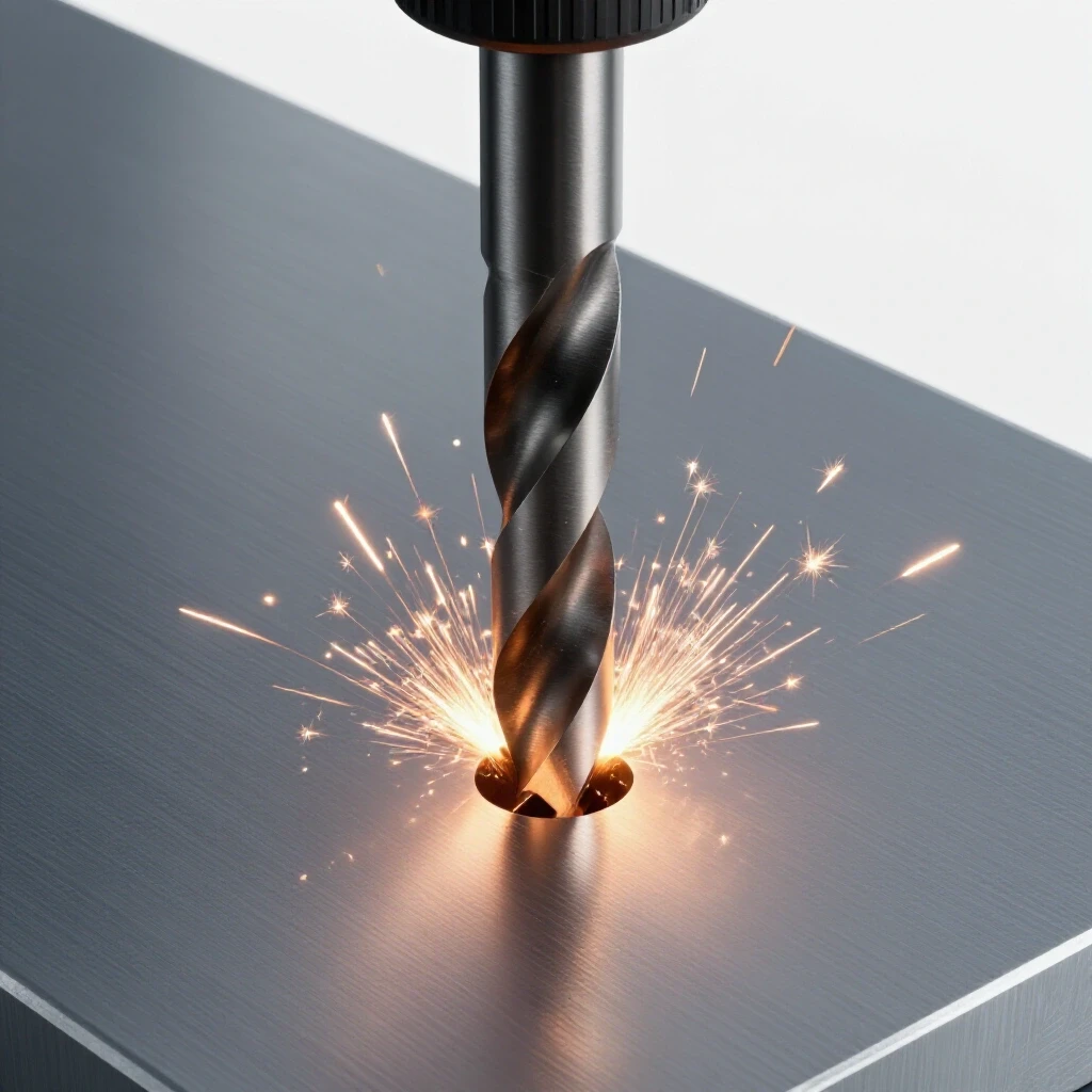
In a workshop environment, we must respect the physical limits of our tools. A standard twist drill is essentially a “roughing” tool. Because it only has two cutting edges and a pointed tip, it tends to wander. If you are building a structural frame where a bolt simply needs to pass through, a drill is fine. However, if you are creating a press-fit for a bearing or a slip-fit for a hardened pin, you need the multi-bladed stability of a finishing tool. These tools have multiple flutes—usually between four and ten—which support the tool against the walls of the hole, preventing the “chatter” or “walking” that ruins precision.
Preparing the Pilot Hole for High-Accuracy Results
A pilot hole is the initial opening created before the final finishing pass. Its size is critical; leaving too much material stresses the tool, while leaving too little results in a hole that isn’t properly cleaned or aligned with the tool’s cutting edges.
The biggest mistake I see intermediate fabricators make is trying to remove too much metal during the final stage. If you leave 1/16 of an inch (1.5 mm) for a finishing tool to remove, the tool will likely bind, snap, or create a finish so rough it looks like a screw thread. For most manual operations in mild steel or aluminum, you want to leave between 0.2 mm and 0.4 mm (0.008″ to 0.015″) of material on the diameter.
Material Removal Benchmarks for Manual Finishing
| Hole Diameter | Drill Size (Decimal) | Material to Remove (Diameter) | Recommended Tool Type |
|---|---|---|---|
| 6 mm (0.236″) | 5.8 mm (0.228″) | 0.2 mm (0.008″) | Straight Flute |
| 12 mm (0.472″) | 11.7 mm (0.460″) | 0.3 mm (0.012″) | Spiral Flute |
| 20 mm (0.787″) | 19.6 mm (0.771″) | 0.4 mm (0.016″) | Chucking Reamer |
| 25 mm+ (1.000″) | 24.5 mm (0.964″) | 0.5 mm (0.020″) | Adjustable Reamer |
When I prepare these holes, I prefer to use a cobalt drill bit for the pilot hole because it holds its edge better and produces a more consistent diameter. If the hole is particularly deep, I ensure I’m clearing chips every 3 mm of depth. A clogged pilot hole creates heat, which can work-harden the metal, making the final finishing pass nearly impossible in materials like stainless steel.
Selecting Tooling for DIY Precision
Selecting the correct tool involves matching the cutter type—such as straight-fluted, spiral-fluted, or adjustable—to the specific material and hole type. Each design handles chip evacuation and alignment differently, impacting the final roundness and surface quality of the workpiece.
For the risk-averse fabricator, understanding the tool geometry is your best defense against a ruined part.
- Hand Reamers: These have a long, slight taper at the front (the “lead”). This taper allows the tool to self-center in the hole. They are turned with a tap wrench, not a power tool.
- Chucking Reamers: These have a much shorter lead and are designed to be held in a drill press or mill. They are excellent for speed but require the workpiece to be perfectly aligned with the machine spindle.
- Spiral Flute Reamers: These are my go-to for holes with “interruptions,” such as a cross-drilled oil hole or a keyway. The spiral flutes bridge the gap, preventing the tool from catching on the edge of the interruption.
- Adjustable Reamers: These are versatile but require care. They use replaceable blades that can be expanded by moving nuts along a threaded body. I use these when I need a “non-standard” size, but they are less rigid than solid tools.
Optimizing Speeds and Feeds for Clean Cuts
Speeds and feeds refer to the rotational velocity of the tool and the rate at which it advances into the metal. In manual finishing, slower speeds and steady pressure are essential to prevent heat buildup, tool chatter, and premature wear on the cutting edges.
One of the hardest habits to break is the urge to run your drill press at high speed. When finishing a hole, your RPM should be roughly half of what you used to drill the hole. If you go too fast, the friction creates heat, the tool expands, and you end up with an oversized hole. Even worse, the tool can “chatter,” creating a wavy, polygonal shape instead of a circle.
I follow a simple “Slow and Steady” protocol: 1. Set the drill press to its lowest or second-lowest belt setting (usually 200–400 RPM for small holes). 2. Apply a constant, firm downward pressure. You want the tool to “bite” and create actual chips, not just rub the surface. 3. If you are doing this by hand, use a T-handle wrench and focus on keeping the tool perpendicular to the work. I often use a “starting guide”—a block of wood or metal with a hole drilled on a professional press—to keep my hand tool straight.
Lubrication and Chip Management Strategies
Lubrication involves applying specialized fluids to reduce friction and heat during the cutting process. Proper fluid selection and chip removal prevent the metal shavings from “re-cutting” or galling the surface, which is vital for maintaining tight tolerances and a mirror-like finish.
Never cut dry. In my early years, I thought a bit of WD-40 was enough for everything. I was wrong. Different metals react differently to the heat of a finishing cut.
Cutting Fluid Selection by Material
- Mild Steel (A36, 1018): Use a high-sulfur cutting oil. It clings to the tool and prevents the chips from welding themselves to the cutting edges.
- Aluminum (6061, 7075): Use kerosene or a specialized aluminum cutting fluid (like A-9). Aluminum is “sticky” and will clog the flutes of your tool instantly without the right lubricant.
- Brass and Bronze: These can often be cut dry, but a light machine oil helps prevent the tool from “grabbing” the soft metal.
- Stainless Steel: Requires a heavy-duty cutting paste. Stainless work-hardens instantly if the tool rubs instead of cuts, so the lubricant must be high-pressure rated.
A critical rule I live by: Never turn the tool backward. Even when you are removing the tool from the hole, continue turning it in the cutting direction (clockwise). Turning it backward can trap chips between the cutting edge and the wall, instantly dulling the tool and scoring your beautiful finish.
Verifying Accuracy with Workshop Measurement Tools
Verification is the final step where you confirm the hole meets design specifications using precision instruments. Tools like telescoping gauges, micrometers, and “go/no-go” pins allow you to detect taper, ovality, or sizing errors that are invisible to the naked eye.
You cannot manage what you cannot measure. If you are aiming for a 0.02 mm tolerance, a standard pair of digital calipers is not enough. Calipers are great for rough work, but they have too much “flex” in the jaws for internal measurements.
I recommend a three-step verification process: 1. Telescoping Gauges: Also known as “snap gauges,” these are inserted into the hole, locked, and then measured with an outside micrometer. This removes the guesswork of trying to feel the “high point” of a bore. 2. Small Hole Gauges: For holes under 12 mm, these split-ball gauges are essential. They expand to fit the bore and provide a solid surface for your micrometer to read. 3. The “Fit Test”: If you are making a hole for a specific pin, use that pin as a gauge. It should slide in with a “hydraulic” feel—smooth, with no side-to-side play, and a slight resistance from the air being displaced.
Workshop Safety Checklist for Finishing Operations
Safety in the machine shop is about managing the energy of rotating tools and the sharp edges of the waste material. Even at low speeds, a finishing tool can catch a workpiece and spin it with enough force to break fingers or cause deep lacerations.
- Secure Workholding: Never hold the workpiece by hand. Use a drill press vise that is bolted to the table. If the tool “grabs,” the vise will keep the part from becoming a helicopter blade.
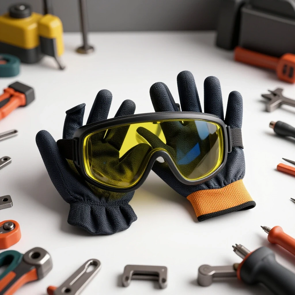
- Eye Protection: Finishing tools often produce long, needle-like chips rather than the curly spirals of a drill bit. These can fly off at unexpected angles.
- No Gloves: This is counter-intuitive to some, but never wear gloves near rotating spindles. A glove can get caught in the flutes and pull your hand into the machine before you can react.
- Debur Promptly: The entry and exit points of a finished hole are razor-sharp. Use a dedicated deburring tool or a large countersink bit to break those edges immediately after the cut.
Troubleshooting Common Finishing Failures
Troubleshooting is the systematic analysis of defects like chatter, oversized holes, or poor surface finish to identify their root causes. By understanding why a tool failed to produce the desired result, you can adjust your technique or setup to prevent future material waste.
| Symptom | Likely Cause | Corrective Action |
|---|---|---|
| Oversized Hole | Speed too high or tool not aligned | Reduce RPM; check spindle-to-work alignment |
| Rough Finish | Insufficient lubrication or dull tool | Use cutting oil; check for chipped tool edges |
| “Bell-Mouthed” Hole | Tool wobbling at entry | Use a guide bushing or check workholding rigidity |
| Spiral Marks | Feeding too fast or turning backward | Reduce downward pressure; never reverse rotation |
| Tool Binding | Too much material left in pilot hole | Use a larger drill bit for the pilot hole |
Case Study: The Failed Bushing Press
A few years ago, I was helping a colleague build a custom suspension arm. He had drilled a 19 mm hole and tried to finish it to 20 mm in one pass using a chucking reamer on a cheap benchtop drill press. The press lacked the torque for such a heavy cut, and the spindle had about 0.1 mm of “runout” (wobble).
The result was a disaster. The hole was 20.15 mm at the top and 19.95 mm at the bottom—a classic “tapered” failure. The bronze bushing he tried to press in went in easy for the first half, then seized and cracked. We had to scrap the entire arm.
The fix was simple: we moved to a more rigid machine, drilled the pilot hole to 19.7 mm, and used a hand reamer with a guide to ensure the tool stayed perpendicular. By taking less material and removing the machine’s wobble from the equation, we achieved a perfect, straight bore.
Conclusion and Next Steps
Mastering the art of internal bore finishing is a journey of patience over power. For the risk-averse fabricator, the goal is to eliminate variables. By controlling your pilot hole size, selecting the right lubricant, and maintaining slow, steady speeds, you can produce parts that rival industrial quality.
If you are ready to start, I suggest practicing on scrap pieces of the same material as your project. Measure the hole after drilling, then measure again after finishing. Document your results in a shop notebook. This data becomes your personal “calibration” for future builds, ensuring that when you move to the final project, you do so with the confidence that comes from proven results rather than guesswork.
Frequently Asked Questions
Can I use a standard drill press for high-precision finishing? Yes, but you must ensure the table is square to the spindle and the workpiece is securely clamped. If your drill press has significant “quill play” (the spindle wobbles when extended), it is better to use a hand tool with a guide block to ensure accuracy.
Why is my finished hole coming out slightly larger than the tool size? This is usually caused by “runout” in your machine spindle or by running the tool at too high an RPM. The centrifugal force causes the tool to whip slightly, cutting a larger path. Excessive heat can also cause the tool or the workpiece to expand during the cut.
How do I know if my finishing tool is dull? A sharp tool will cut quietly and produce clean, consistent chips. If you hear a high-pitched squeal, see “tearing” marks on the metal surface, or find that you have to apply excessive pressure to make the tool cut, it is likely dull or has “built-up edge” (metal welded to the teeth).
Is it better to use a straight flute or a spiral flute tool? For most solid materials, a straight flute is standard and easier to sharpen. However, if your hole has a gap (like a slot or a cross-hole), you must use a spiral flute. The spiral ensures that at least some part of the cutting edge is always in contact with the solid wall, preventing the tool from catching.
What is the best way to clean a finishing tool after use? Use a stiff nylon or brass brush to remove chips from the flutes. Never use a steel wire brush, as it can dull the cutting edges. Wipe the tool down with a light coat of machine oil to prevent rust before storing it in a dedicated case.
Can I sharpen these tools myself? Manual sharpening is extremely difficult because all cutting edges must be exactly the same height to work correctly. If one blade is higher than the others, it will do all the work and the hole will be out-of-round. It is usually more cost-effective to replace the tool or have it professionally ground.
What happens if I leave too little material for the final pass? If the “chip load” is too small, the tool will simply rub against the metal instead of cutting. This creates intense heat, dulls the tool, and can result in a “burnished” surface that is actually harder than the rest of the part, making further adjustment difficult.
How do I finish a “blind” hole that doesn’t go all the way through? Use a “bottoming” tool. These have almost no taper at the tip, allowing them to cut all the way to the bottom of the hole. You must be extremely careful to clear chips frequently, as they have nowhere to go and can pack into the bottom, causing the tool to break.
Does material thickness affect the process? Yes. In very thin materials (less than 3 mm), a finishing tool can easily “grab” and pull itself through, potentially deforming the sheet. In thick materials, heat management and chip evacuation become the primary concerns.
Can I use these techniques on hardened steel? Standard high-speed steel (HSS) tools will not cut hardened steel; they will simply melt. For hardened materials, you would need carbide tooling, which is much more brittle and generally requires a rigid milling machine rather than a hand-held or DIY setup.
(This article was written by one of our staff writers, James Harlan. Visit our Meet the Team page to learn more about the author and their expertise.)