How to Design and Build Scale Mockups for Projects (Guide)
I remember a custom cantilevered gate project from my seventh year in the shop. I had designed it on paper, calculated the weights, and felt confident. But when we hung the full-sized steel frame, it developed a persistent, rhythmic wobble every time it closed. The structural metal load capacity was fine, but the torsional rigidity was lacking. I had to cut into a finished, powder-coated piece of work to add gussets. That was the day I stopped trusting paper alone and started building physical metal prototypes.
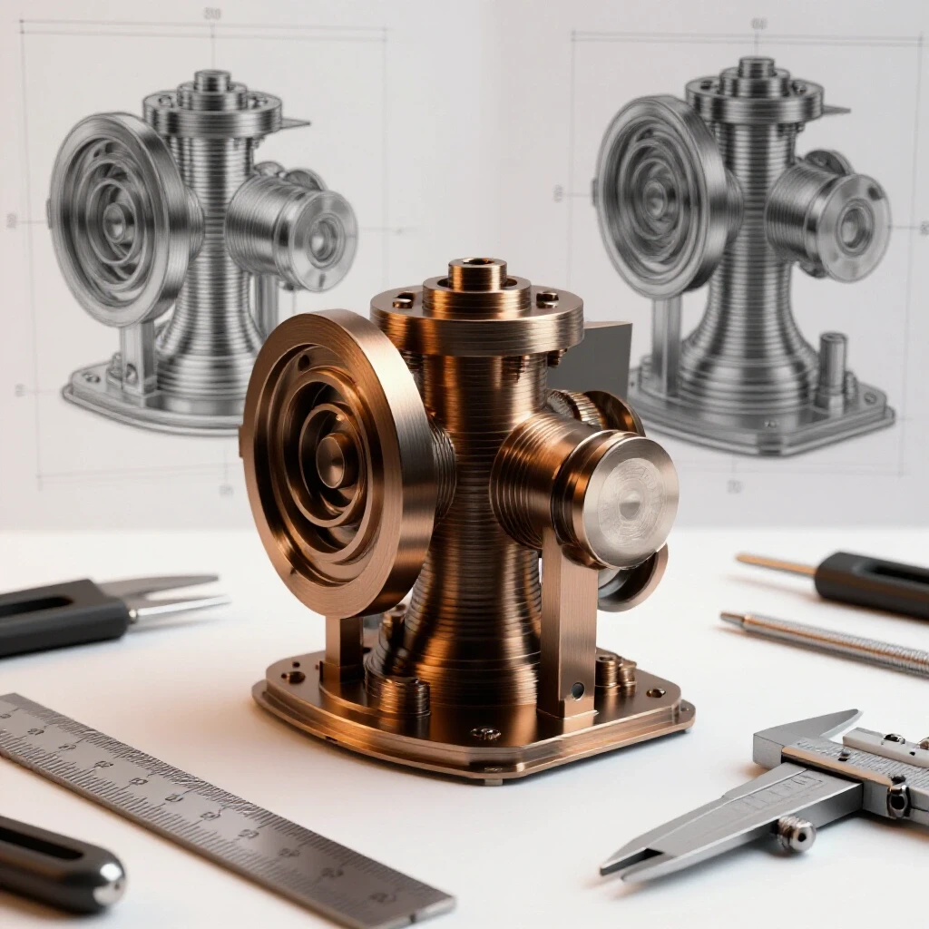
In my 14 years as a fabricator and inspector, I have seen that the most expensive mistakes happen when we move too quickly from a concept to a final heavy build. A physical model, built to a specific ratio like 1:4 or 1:8 using the same materials and joining methods as the final project, acts as a sacrificial lamb. It tells you where the metal will warp, where the weld will pull, and where the stress will concentrate before you weld a single bead on your expensive main stock.
Fabrication is rarely about a single catastrophic snap; it is usually about the cumulative effect of small errors. By creating a reduced-scale version of your project, you are conducting a real-world simulation of physics. This guide focuses on how to use these physical models to ensure your final structures are safe, aligned, and built to last.
Analyzing Structural Mechanics through Physical Prototypes
Structural mechanics involves the study of how physical forces like tension, compression, and shear move through a metal frame. When we build a smaller version of a project, we are testing how these forces interact with our chosen joint designs and material thicknesses.
Building a model allows you to see the “load path,” which is the continuous route that a load takes through the structural members to the foundation or support. If a joint is poorly placed, you will see the metal in your model flex or distort under a simulated load. This is much safer than finding out your garage fabrication safety was compromised when a full-sized workbench or hoist fails under weight.
I often use a 1:4 scale because the math is simple. If my final project uses 2-inch square tubing with a 1/8-inch wall, I might use 1/2-inch tubing for the model. This allows me to see how the heat from the welder affects the thin walls. It also lets me test the assembly sequence. If I cannot get my welding torch into a tight corner on the model, I certainly will not be able to do it on the full-sized version.
Managing Material Stress and Heat Affected Zones
The Heat Affected Zone, or HAZ, is the area of base metal that did not melt during welding but had its internal structure changed by the intense heat. This zone is often the weakest point in a fabrication because the heat can make the metal more brittle or prone to cracking.
In a smaller model, the HAZ represents a much larger percentage of the total material compared to a full-sized beam. This is actually a benefit for the risk-averse fabricator. If your scale model survives the welding process without warping or cracking in the HAZ, your full-sized project is much more likely to be structurally sound.
When welding these smaller components, I pay close attention to the cooling rate. If the metal cools too quickly, you risk “brittle fracture,” where the metal snaps like glass rather than bending. I always keep a temperature stick or an infrared thermometer handy to monitor the interpass temperature, ensuring the metal stays within a safe range for its specific alloy.
Metal Load and Stress Tolerances (Common Shop Steels)
| Material Type | Yield Strength (PSI) | Tensile Strength (PSI) | Common Use Case |
|---|---|---|---|
| A36 Mild Steel | 36,000 | 58,000 – 80,000 | General frames, brackets |
| 1018 Cold Rolled | 54,000 | 64,000 | Shafts, pins, precision parts |
| 4130 Chromoly | 63,000 – 70,000 | 85,000 – 110,000 | Lightweight high-strength frames |
| 6061-T6 Aluminum | 35,000 | 42,000 | Lightweight structures (non-welded) |
Yield strength is the point where the metal stays bent. Tensile strength is the point where it actually pulls apart.
Implementing a Workshop Safety Checklist for Fabrication Testing
Workshop safety is not just about wearing goggles; it is about controlling the environment where high-energy processes like welding and grinding occur. Before I start any prototype build, I go through a rigorous garage fabrication safety routine to ensure that a small project doesn’t lead to a big accident.
I start with the “five-foot rule”: nothing flammable within five feet of the welding table. This includes sawdust, oily rags, and chemical cleaners. I also check my shielding gas flow rate. For most small-scale TIG or MIG work on a model, a flow rate of 15–20 CFH (cubic feet per hour) is the sweet spot. Too little gas leads to weld porosity; too much creates turbulence that sucks in oxygen, also causing porosity.
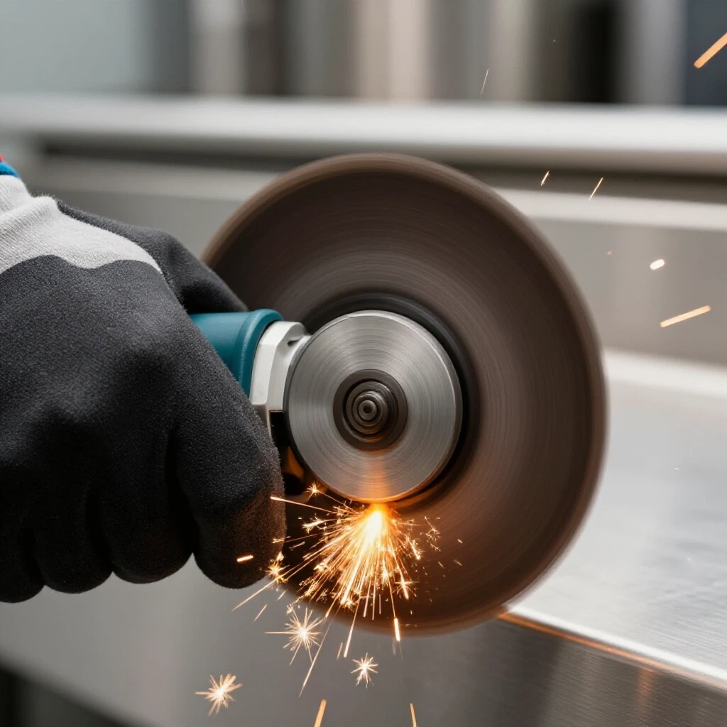
Your Personal Protective Equipment (PPE) must be rated for the specific task. For welding the fine joints of a scale model, I prefer a Shade 10 or 11 filter. This gives me enough visibility to see the tiny weld puddle without straining my eyes. If I am grinding the edges of sheet metal for the mockup, I always wear a full-face shield over my safety glasses to protect against high-velocity metal slivers.
Essential Workshop Safety Checklist
- Verify fire extinguisher is charged and within reach.
- Check welding leads for cracks or exposed copper.
- Ensure ventilation is pulling fumes away from your face.
- Set gas flow rate to 15–20 CFH.
- Inspect PPE for holes or UV damage.
- Clear all trip hazards from the work zone.
Troubleshooting Weld Defects in Scaled Components
Weld defects are internal or external flaws that compromise the strength of a joint. In scale models, these defects are often “micro-sized” but provide huge clues about what will happen on the final build. The most common issue I see is weld porosity, which looks like tiny pinholes in the metal.
Porosity is usually caused by dirty metal or poor gas coverage. If I see porosity on my mockup, I know I need to be more aggressive with my pre-welding cleaning on the full-sized project. I use a dedicated stainless steel wire brush that has never touched aluminum or carbon steel to avoid cross-contamination.
Another critical defect is “lack of fusion,” where the weld metal doesn’t actually bond with the base metal. This often happens because the fabricator is afraid of burning through the thin metal of a scale model. If your model joints fail when you drop them on the floor, you have a fusion problem. You must find the balance between enough heat for a deep bond and low enough heat to prevent warping.
Weld Defect Causes and Solutions
| Defect Type | Primary Cause | Visual Indicator | Corrective Action |
|---|---|---|---|
| Porosity | Contamination or low gas | Tiny holes/spongy look | Clean metal; check gas flow (15-20 CFH) |
| Undercut | Excessive heat/wrong angle | Groove at the weld edge | Lower amperage; adjust torch angle |
| Lack of Fusion | Low heat/fast travel | Weld sits “on top” of metal | Increase heat; slow down travel speed |
| Cracking | Brittle HAZ/high stress | Thin line through weld | Pre-heat metal; use correct filler rod |
Step-by-Step Construction of a Metal Prototype
Building a physical model requires a different mindset than final fabrication. You are not just building a “mini version”; you are building a data point. I start by selecting material that is proportional to my final design. If I am building a large structural rack, I might use 16-gauge sheet metal for the mockup to represent the thicker plates I will use later.
First, I use a manual shear or a cold saw to cut my pieces. Abrasive saws generate too much heat for small parts and can distort the edges before you even start welding. Once the pieces are cut, I use a metal brake to create any necessary bends. This allows me to see if the material will “spring back” or if the bend radius is too tight, which can cause the metal to crack.
Next, I perform a “dry fit.” I clamp everything together using small C-clamps or Cleco fasteners. This is the moment where most design errors reveal themselves. If the parts don’t align perfectly at 1:4 scale, they will be a nightmare at full scale. Once aligned, I use tiny tack welds—just enough to hold the structure—before I commit to full beads.
The Prototype Build Sequence
- Material Selection: Choose gauges that reflect the final thickness ratio.
- Precision Cutting: Use shears or cold saws to keep edges clean and square.
- Bending and Forming: Test the limits of the metal’s ductility.
- The Dry Fit: Check for alignment and interference issues.
- Tack Welding: Secure the structure while allowing for minor adjustments.
- Full Welding: Observe heat distortion patterns across the frame.
Advanced Diagnostic Inspection for Prototypes
Once the model is welded, I don’t just look at it and say “looks good.” I use diagnostic tools to find what the eyes miss. One of my favorite methods is using a Dye Penetrant Inspection (DPI) kit. You spray a red dye on the weld, wipe it off, and then apply a white developer. If there are any cracks—even ones you can’t see—the red dye will bleed through the white powder.
I also perform a “crush test” on non-critical mockups. I place the model in a hydraulic press or under a heavy weight to see where it fails first. Does the weld snap? Does the tube buckle? This tells me exactly where I need to add reinforcement. In the engineering world, we aim for a safety factor of at least 2:1, meaning the structure should hold twice the weight it is rated for. For overhead or critical safety items, I push for a 4:1 safety factor.
Modern non-destructive testing (NDT) has become very affordable for the home shop. You can now buy digital calipers with high precision to measure “weld throat” thickness. If your weld is too thin, it won’t carry the load. If it’s too thick (over-welding), you’ve added unnecessary heat and stress to the joint, which can lead to warping.
Designing for Thermal Expansion and Distortion
Metal expands when it gets hot and contracts as it cools. This is the primary cause of warping in metal fabrication. When you weld one side of a joint, the cooling metal pulls the rest of the structure toward the weld. In a scale model, this effect is magnified.
To combat this, I use “back-stepping” or “staggered welding.” Instead of running one long bead from left to right, I weld a small section, move to the opposite side of the project, weld a section there, and then come back. This balances the heat input. I also use “fixturing,” which means clamping the project to a thick steel table to force it to stay flat while it cools.
Interestingly, you can also use “pre-distortion.” If I know a weld will pull a piece 2 degrees to the left, I will intentionally clamp it 2 degrees to the right before I start. When the weld cools, it pulls the piece into the perfect 90-degree angle. Seeing this happen on a small-scale model is the only way to accurately predict how much pre-distortion you need for the big version.
Calculating Structural Load and Safety Margins
Understanding the math behind your build is the difference between a project that lasts and one that fails. We use PSI (pounds per square inch) to measure the stress on a joint. If you have a weld that is 1 inch long and 1/8 inch thick, and you put 1,000 pounds of force on it, that weld is under 8,000 PSI of stress.
Looking back at our material table, A36 steel has a yield strength of 36,000 PSI. In theory, that 1,000-pound load is safe. However, as a risk-averse fabricator, I never operate near the yield point. I want my actual stress to be a fraction of the yield strength. This accounts for “dynamic loads,” like a person jumping on a trailer or a gust of wind hitting a sign.
When testing your scale model, you can apply proportional weights. If your model is 1:4 scale, the weight it holds doesn’t scale linearly; it follows the square-cube law. This is why physical testing is so vital—it reveals the complex relationship between size, weight, and strength that simple math sometimes misses.
Structural Joint Failure Analysis
- Shear Failure: The weld “slides” off the base metal. Usually caused by insufficient penetration.
- Tensile Failure: The metal stretches and thins until it snaps. Caused by overloading the material’s yield strength.
- Buckling: The vertical member folds under compression. Caused by using material that is too thin for its length.
- Fatigue: Small cracks grow over time due to repeated loading and unloading.
Final Inspection and Transitioning to Full Scale
The final step in the mockup process is the “post-mortem” analysis. I take my model and compare it to my original drawings. I look for any place where the metal moved more than 1/16th of an inch. I check every weld for undercut—that little groove at the edge of the weld that acts like a “perforated line” for a future crack.
If the model passes my inspection and a basic load test, I am ready to buy the full-sized steel. I take my “weld map” from the model—the notes I made about which joint to weld first and how much heat to use—and I follow it exactly. This consistency is what separates professional-grade fabrication from “garage guesswork.”
I also use this time to refine my shop safety layout. If I realized during the mockup that I needed more space to swing a long piece of tubing, I moved my welding table before the heavy steel arrived. A clean, organized shop is a safe shop, and a safe shop produces high-quality work.
Recommended Fabrication Tools for Testing
- Digital Calipers: For measuring material thickness and weld profiles.
- Dye Penetrant Kit: For finding hidden surface cracks in welds.
- Infrared Thermometer: To monitor Heat Affected Zone temperatures.
- Angle Finder: To check for distortion after the metal cools.
- Electronic Gas Flow Meter: To verify your regulator is accurate at the torch.
The journey from a hobbyist to a skilled fabricator is paved with the pieces of projects that didn’t go quite right. By embracing the process of building physical metal prototypes, you are choosing to learn those lessons on a small, safe, and inexpensive scale. You are not just building a model; you are building the confidence that your final project will stand the test of time and the rigors of physics.
FAQ: Mastering Physical Metal Prototypes
Why should I build a physical model instead of just using a computer program? Computer programs are excellent for geometry, but they often struggle to predict “real-world” variables like weld distortion, the skill of the welder, and subtle material inconsistencies. A physical metal model shows you exactly how the heat will move through the specific alloy you are using and how difficult the joints will be to reach with your actual tools.
What is the best scale for a shop prototype? For most garage projects, 1:4 is the gold standard. It is small enough to save money on materials but large enough that you can still use standard welding techniques and see the results clearly. If the project is massive, like a car trailer, 1:8 or 1:10 might be more practical.
Does a scale model really represent the strength of the full-sized project? It represents the behavior of the structure. While the weight-to-strength ratio changes as things get bigger (the square-cube law), the “failure points” usually remain the same. If a joint twists on the model, it will twist on the full-sized version.
How do I prevent my small model from warping into a pretzel? Use very short weld beads and allow the metal to cool completely between passes. You can also “heat sink” the model by clamping it to a large, flat piece of thick aluminum or copper, which will pull the heat away from the thin prototype metal.
Is it okay to use different metals for the mockup? No. To get accurate data, you must use the same family of metal. If your final project is stainless steel, your mockup must be stainless. Different metals have different thermal expansion rates and weldability characteristics.
What is the most common mistake when building these models? Over-welding. Fabricators often put a full-sized weld bead on a tiny model. This puts way too much heat into the part. You should scale your weld size down just like you scale the material size.
How do I know if my weld penetration is deep enough on a small part? The best way is a “destructive test.” Weld a sample joint exactly like the one on your model, then cut it in half with a saw and sand the edge smooth. You will be able to see exactly how deep the weld metal went into the base metal.
Can I reuse the material from my mockups? Generally, no. The metal has been through a lot of heat cycles and may have internal stresses or brittleness. Keep your successful mockups as a reference for future builds or as a “teaching tool” to show others how the structure works.
Do I need a special welder for small-scale prototypes? Not necessarily, but TIG (Tungsten Inert Gas) welding is often preferred for models because it allows for much finer control over the heat and the weld puddle. If you only have a MIG welder, use the thinnest wire available (like .023″) and lower your settings.
How much time should I spend on a mockup? A good rule of thumb is that the mockup should take about 10-20% of the time you expect to spend on the final project. If a project will take 40 hours, spending 4-8 hours on a prototype can easily save you 10 hours of “fixing” mistakes on the final build.
(This article was written by one of our staff writers, James Harlan. Visit our Meet the Team page to learn more about the author and their expertise.)