How to Speed Up Your Metal Layout and Marking Process (Tips)
In my 14 years on the shop floor and as a structural inspector, I have seen that the most expensive mistakes rarely happen during the final weld. Instead, they happen in the first twenty minutes of a project. When a fabricator rushes through the initial marking phase, they invite a cascade of errors that can lead to misaligned joints and structural instability. I have inspected heavy equipment frames where a simple 1/8-inch measurement error resulted in a load path that missed its intended support, leading to a hairline fracture under stress. Improving the way you transfer dimensions to steel is not just about moving faster; it is about building a repeatable system that eliminates the “measure twice, cut once” anxiety.
Establishing Reliable Reference Points for Precision
A reference point, often called a datum, is a fixed starting position used for every measurement on a workpiece. By using a single edge or corner as a base, you prevent cumulative errors that occur when measuring from one mark to the next. This foundational step ensures that every part of the assembly aligns perfectly with the original design.
Selecting a Primary Datum Edge
The primary datum is the most important surface on your stock, serving as the “zero” point for all subsequent markings. You should choose the straightest, cleanest edge available and mark it clearly with a small “D” or an arrow. This prevents you from accidentally switching sides halfway through the project, which is a common cause of parts being out of square.
When I work with hot-rolled steel, the first thing I do is check the factory edge for straightness. Factory edges are rarely perfect. If I am building a frame that requires high precision, I will grind or mill one edge true before I start my layout. This extra five minutes of preparation can save hours of grinding and shimming during the fit-up stage.
Utilizing Centerlines for Symmetrical Layouts
Centerlines are imaginary lines that divide a part into equal halves, providing a balanced starting point for hole patterns and brackets. Instead of measuring from an outside edge that might be uneven, you establish a center mark and work outward in both directions. This technique is essential for ensuring that loads are distributed evenly across a structural component.
In structural inspection, we often find that bolt holes fail to line up because the fabricator measured from left to right across a piece of plate. If the plate width varies by even a tiny amount, the last hole will be off. By using a centerline, any variation in the material width is split between the two outer edges, keeping the critical internal dimensions perfectly centered and structurally sound.
High-Visibility Marking Techniques for Faster Workflow
High-visibility marking involves using specialized dyes and scribing tools to create high-contrast lines on metal surfaces. These methods allow a fabricator to see exactly where a cut or drill bit needs to land, reducing eye strain and guesswork. Clearer lines lead to more confident tool placement and fewer scrapped parts.
The Role of Layout Fluids in Accuracy
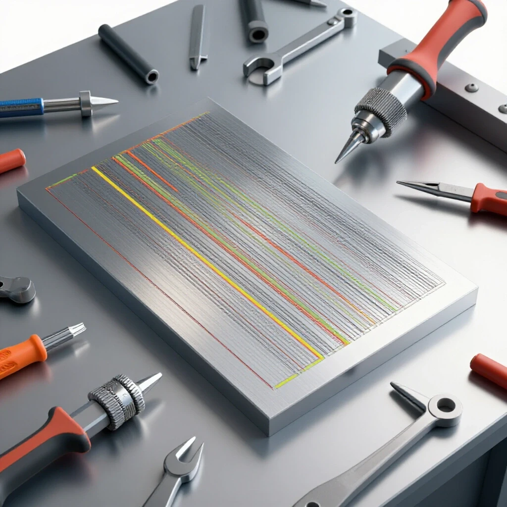
Layout fluid, commonly known by brand names like Dykem, is a thin blue or red dye applied to the metal surface. Once dry, a metal scribe is used to scratch through the dye, revealing a bright, shiny line of bare steel underneath. This creates a high-contrast mark that is much thinner and more precise than any marker or pencil.
I prefer layout fluid because it does not rub off as easily as soapstone or permanent markers. When you are moving heavy steel around the shop, your hands and gloves will inevitably smudge your marks. A scribed line in layout dye remains visible even if the part gets covered in oil or dust. This durability allows you to move through multiple fabrication steps without having to re-measure.
Scribing Versus Ink-Based Marking
Scribing is the process of using a hardened steel or tungsten carbide tip to scratch a physical groove into the metal. Unlike ink, which has a measurable thickness, a scribed line is remarkably thin and sits exactly where the tool was placed. This level of precision is necessary for parts that must fit together with tight tolerances.
- Scribe Accuracy: Typically within 0.005 to 0.010 inches.
- Permanent Marker Accuracy: Typically within 0.030 to 0.060 inches.
- Soapstone Accuracy: Typically within 0.060 to 0.125 inches.
While a marker is fine for rough cuts, I always reach for a scribe when I am marking hole centers or bend lines. If you are aiming for a professional-grade fit-up, you cannot rely on a thick felt-tip line. The width of the ink itself can hide an error that will cause a joint to gap during welding.
Essential Tooling for Rapid Measurement Transfer
Specialized layout tools allow you to transfer dimensions from a drawing to the metal without using a tape measure for every single line. These tools act as physical memory, holding a specific measurement so you can repeat it across multiple parts. This approach drastically reduces the chance of a “transposition error,” where you misread a number on the tape.
Maximizing the Use of Combination Squares
A combination square is a multi-purpose tool consisting of a ruled blade and a sliding head that can be locked at 90 or 45 degrees. It is the workhorse of the metal shop, used for checking squareness, measuring depths, and scribing parallel lines. By locking the head at a specific dimension, you can slide it along an edge to mark a consistent offset.
I often use my square as a physical stop. If I need to mark a series of holes 2 inches from the edge of a plate, I lock the square at 2 inches and use it to guide my scribe. This is much faster than marking 2 inches at several points and then drawing a line through them. It also ensures that the line is perfectly parallel to the datum edge.
Dividers and Trammel Points for Circular Layouts
Dividers are compass-like tools with two sharp metal points used for stepping off equal distances or scribing circles and arcs. Trammel points are similar but are clamped onto a long bar to layout much larger radii. These tools are invaluable for marking bolt circles or creating rounded corners on heavy plate.
| Tool Type | Best Use Case | Precision Level |
|---|---|---|
| Combination Square | Parallel lines and 90-degree checks | High |
| Dividers | Repeating small increments or arcs | Very High |
| Trammel Points | Large radius marking (over 12 inches) | High |
| Surface Gauge | Transferring heights on a flat table | Exceptional |
When I am laying out a circular flange, I use dividers to “walk” the circumference. Once I set the dividers to the required chord length, I can mark the center of every bolt hole in seconds. This mechanical method is far more reliable than trying to measure around a curve with a flexible tape.
Template and Jig Strategies for Repeatable Accuracy
Templates and jigs are physical patterns used to guide the marking or cutting of multiple identical parts. Instead of measuring every piece of steel from scratch, you create one “master” version and use it to replicate the others. This strategy is the most effective way to ensure consistency across a large project.
Creating Durable Shop Templates
A template can be as simple as a piece of cardboard or as robust as a sheet of thin gauge steel. For projects involving complex curves or specific hole patterns, I recommend making a steel template. You can drill the holes in the template, then simply clamp it to your workpiece and use a transfer punch to mark the hole centers.
Using a transfer punch is a critical technique. A transfer punch is a tool that fits snugly into a hole in a template and has a small point in the center. When you tap it with a hammer, it leaves a perfectly centered dimple on the metal underneath. This eliminates the “wandering” that happens when you try to eye-ball the center of a hole.
The Advantage of “Story Poles” in Large Frames
A story pole is a long strip of wood or metal that has all the critical dimensions for a project marked on it. If you are building a large trailer frame or a structural rack, you mark the locations of all cross-members on the story pole first. You then lay the pole against your long frame rails and transfer the marks directly.
This technique prevents the cumulative error that happens when you move a tape measure down a 20-foot beam. If your tape is slightly crooked or if you misread one mark, every subsequent mark will be wrong. With a story pole, the relationship between every cross-member is locked in, ensuring the frame stays square and true.
Advanced Techniques for Geometric Layout
Geometric layout uses the principles of math and physics to find centers, angles, and perpendicular lines without relying on pre-made squares. These methods are essential when you are working with large pieces of steel that are bigger than your shop tools. Understanding these “old-school” methods can save a project when your standard tools aren’t long enough.
The 3-4-5 Rule for Large-Scale Squaring
The 3-4-5 rule is based on the Pythagorean theorem, stating that a triangle with sides of 3, 4, and 5 units will always have a 90-degree angle. In metal fabrication, you can use any multiple of these numbers (like 6-8-10 or 9-12-15) to check the squareness of a large frame. This is often more accurate than using a small framing square on a large assembly.
- Measure 3 feet from a corner along one rail and make a mark.
- Measure 4 feet from the same corner along the perpendicular rail and make a mark.
- Measure the diagonal distance between the two marks.
- If the distance is exactly 5 feet, the corner is perfectly square.
I have used this method to square up heavy equipment trailers that were 30 feet long. At that scale, a standard square is useless because a tiny error at the corner becomes a massive gap at the other end. The 3-4-5 rule provides a “macro” view of the structure’s geometry, ensuring the load paths are aligned correctly.
Finding the Center of Round Stock
Locating the exact center of a round bar or pipe is notoriously difficult with a tape measure. A center head, which is part of a combination square set, is designed specifically for this task. You place the V-shaped head against the round stock and scribe a line across the face. By rotating the bar 90 degrees and scribing again, the intersection of the two lines marks the center.
If you don’t have a center head, you can use a “hermaphrodite caliper.” This tool has one straight leg and one curved leg. You set the caliper to slightly more than the radius, hook the curved leg on the outside of the bar, and scribe an arc. By doing this from four different sides, you create a small “box” in the middle. The center of that box is the center of your bar.
Verification Checklists Before the First Cut
The final step in any layout process is a rigorous verification of the marks. Once the metal is cut or drilled, mistakes become much harder and more expensive to fix. I always treat my layout as a “draft” until I have performed a series of checks to confirm everything is in the right place.
The “Overall Dimension” Double-Check
Before I start cutting, I always measure the total length of the layout and compare it to the blueprint. It is easy to get caught up in the details of small brackets and lose track of the big picture. If the individual segments of your layout don’t add up to the correct total length, you know there is a mistake somewhere in the middle.
- Check total length against the cut list.
- Verify that all “mirror image” parts are actually mirrored and not identical.
- Confirm that hole diameters match the intended fasteners.
- Ensure that bend allowances have been factored into the flat length.
In my inspection work, I’ve seen entire batches of parts scrapped because the fabricator forgot to account for the thickness of the material when marking a bend. A part that is supposed to be 10 inches wide after two 90-degree bends must be marked differently than a flat 10-inch plate.
Visualizing the Assembly Fit-Up
Take a moment to look at your marks and imagine how the pieces will fit together. Does the layout make sense? Are the holes placed far enough from the edge to maintain structural integrity? This “sanity check” is often where I catch the most glaring errors.
If you are welding a heavy bracket to a beam, ensure your marks leave enough room for the weld bead. I have seen many layouts where the hole was placed so close to a corner that the welding torch couldn’t reach the joint properly. Good layout considers the physical limitations of the welding process, not just the dimensions on the paper.
Improving Accuracy with Proper Tool Maintenance
Your layout is only as good as the tools you use. A dropped square or a dull scribe will lead to errors that are difficult to track down. Maintaining your layout kit is a fundamental part of being a professional fabricator.
Calibrating Your Squares and Rules
You should periodically check your squares for accuracy. To check a combination square, hold the head against a known straight edge and scribe a line. Flip the square over and see if the blade aligns perfectly with the line you just drew. If there is a gap, the square is out of alignment and should be adjusted or replaced.
I keep a “master” rule in a drawer that I never use for layout. I only use it to check the accuracy of the tape measures and rules I use daily. Over time, the “hook” on the end of a tape measure can become bent or loose, leading to measurements that are off by 1/32 of an inch. While that sounds small, it is enough to cause a structural joint to fit poorly.
Keeping Scribes Sharp for Fine Lines
A dull scribe creates a wide, fuzzy line that is hard to follow. I use a diamond whetstone to keep my carbide-tipped scribes razor-sharp. A sharp scribe requires less pressure, which gives you better control and prevents the tool from slipping across the metal.
When I am marking critical center points for drilling, I use a prick punch followed by a center punch. A prick punch has a sharper point (usually 30 to 60 degrees) and is used to accurately locate the mark. A center punch has a blunter point (90 degrees) and is used to enlarge the mark so the drill bit has a stable place to start. This two-step process ensures the hole doesn’t “walk” away from your layout line.
Summary of Layout Best Practices
Mastering the layout process is about discipline and the right tools. By establishing clear datums, using high-contrast marking fluids, and employing physical templates, you can significantly increase your speed without sacrificing the structural integrity of your builds. Remember that the layout is the foundation of your project; if it is flawed, the rest of the build will struggle to succeed.
- Always use a datum: Never measure “chain-style” from one mark to the next.
- Scribe for precision: Use a metal scribe and layout fluid for lines that need to be exact.
- Trust your squares: Regularly check your tools for 90-degree accuracy.
- Use physical templates: For repetitive parts, a steel template is faster and more accurate than a tape measure.
- Verify before cutting: Perform an overall dimension check to catch “big picture” errors.
By implementing these strategies, you will find that your projects come together more easily, your welds fit tighter, and your finished structures are more reliable. Speed in the shop comes from a lack of mistakes, and a solid layout is the best way to ensure your first attempt is your final one.
Frequently Asked Questions
Why shouldn’t I just use a tape measure for everything?
Tape measures are great for long distances but lack the precision needed for tight-fitting joints. The “hook” on the end can move, and the thickness of the blade makes it hard to mark exactly. For anything under 12 inches, a machinist’s rule or a combination square is much more accurate and repeatable.
What is the best way to mark on dark or scaly hot-rolled steel?
For hot-rolled steel, I recommend using a silver-colored layout pencil or a thin soapstone for rough lines. For precision work, grind a small area clean and apply layout fluid (Dykem). This allows you to scribe a bright line that stands out against the dark mill scale.
How do I prevent my marks from disappearing during grinding or welding?
Scribing a physical groove into the metal is the best way to preserve your marks. Even if the ink or dye burns off, the scratched line will remain visible. You can also use a center punch to make “witness marks” along a line, which will survive even heavy grinding.
What is “cumulative error” and how do I avoid it?
Cumulative error happens when you measure from point A to point B, then from point B to point C. If each measurement is off by just 1/32 of an inch, by the time you get to point F, you could be off by nearly a quarter inch. To avoid this, always measure from a single starting point (the datum) to every other point.
How do I know if my framing square is actually square?
Use the “line flip” test. Hold one leg of the square against a perfectly straight edge and draw a line along the other leg. Flip the square over so it faces the opposite direction and align it with the same starting point. If the square doesn’t line up with the mark, it is out of square.
Is there a faster way to mark centers on square tubing?
Yes, use a “centering square” or a simple V-block layout tool. You can also set a combination square to exactly half the width of the tube and mark from both sides. Where the two lines meet (or if they overlap perfectly) is your center.
When should I use a transfer punch instead of a center punch?
Use a transfer punch when you are copying a hole pattern from an existing part or a template. The transfer punch is sized to fit the hole perfectly, ensuring the new mark is exactly in the center. Use a center punch for general layout where you are starting from a scribed crosshair.
Can I use a standard pencil for metal layout?
A standard graphite pencil is usually too thick and doesn’t show up well on steel. Furthermore, graphite can actually cause issues with certain types of stainless steel welds (carbon contamination). Use a silver layout pencil, a scribe, or a specialized metal marker instead.
How do I layout a 45-degree miter cut quickly?
Most combination squares have a 45-degree face built into the head. Simply slide the head to the end of your material, align the 45-degree shoulder with the edge, and scribe your line. For larger material, use a speed square, but verify its accuracy first.
What is the most common layout mistake beginners make?
The most common mistake is failing to account for the “kerf” or the width of the saw blade. If you mark your steel at exactly 12 inches and cut on the line, your finished piece will be about 11-7/8 inches long because the blade turned 1/8 inch of steel into dust. Always mark your cut on the “waste” side of the line.
(This article was written by one of our staff writers, James Harlan. Visit our Meet the Team page to learn more about the author and their expertise.)