How to Control Heat Input and Prevent Burn-Through (Tips)
In my 14 years of inspecting industrial steel and managing shop floor fabrication, I have seen many projects ruined by a single second of inattention. I remember early in my career, I was working on a custom fuel tank made from 16-gauge cold-rolled steel. I was confident, perhaps too confident, and I didn’t account for how quickly heat builds up in such a thin cross-section. Within inches of a seemingly good bead, the metal suddenly gave way, leaving a gaping hole that no amount of “stacking dimes” could fix. That moment taught me that heat is not just a tool; it is a force of physics that must be strictly managed.
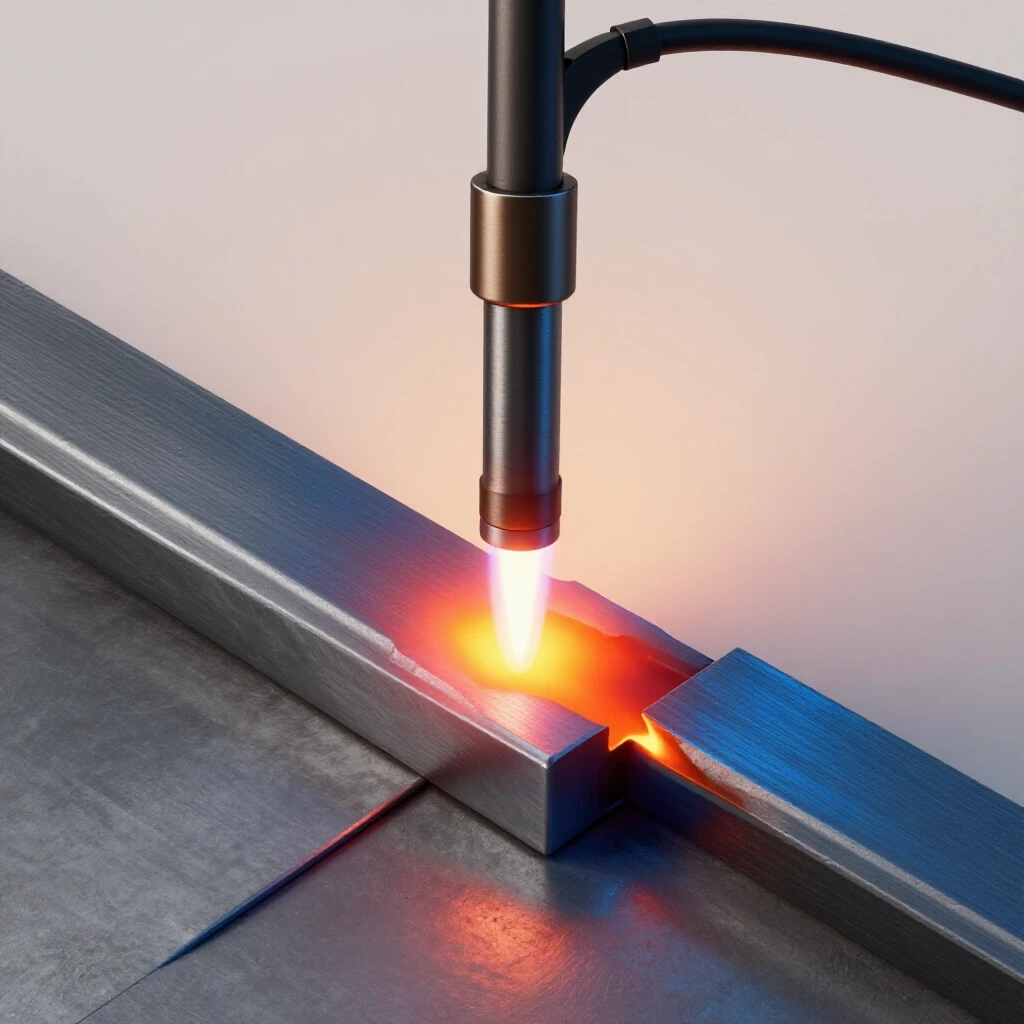
For those of us working in home shops or small garages, the margin for error is thin. When you are dealing with sheet metal or thin-walled tubing, the difference between a strong joint and a structural failure is often just a few amps or a fraction of an inch in torch position. My goal is to help you look at your welding through the lens of a quality inspector. We will focus on the data, the observable signs of material stress, and the technical adjustments needed to keep your projects structurally sound.
Understanding Thermal Stress and Material Thresholds
Thermal stress occurs when metal expands and contracts at different rates due to localized heating. In thin materials, this often leads to warping or total melting of the base metal. When we apply an arc to a joint, we are creating a microscopic battleground where the metal is trying to dissipate energy while maintaining its shape.
The Heat Affected Zone and Structural Weakness
The heat affected zone weakness refers to the area of base metal that has not melted but has had its microstructure altered by the intense temperature. This region is often where structural failures begin because the metal may become more brittle or lose its original tensile strength. For common A36 structural steel, the yield strength is typically around 36,000 PSI, but excessive heat can drop this significantly in the area immediately surrounding the weld.
In my inspections, I use a simple rule: the wider the HAZ, the higher the risk of distortion. If you see a rainbow of colors extending far from your bead, you are pumping too much energy into the part. This is a critical indicator in any welding defect troubleshooting process. You want to see a narrow, focused band of discoloration, which suggests that the heat was moved along the joint quickly enough to prevent deep structural soaking.
Physical Load Limits and Thin-Gauge Dynamics
When we work with thin sheet, we are often pushing the material to its physical load limits during the welding process itself. Thin metal cannot “sink” heat as effectively as a thick plate. Because there is less mass to absorb the energy, the temperature rises almost instantly to the melting point. If your travel speed does not match this rise, the puddle will drop out, creating a burn-through.
- 18-gauge steel (approx. 0.048 inches) melts almost instantly under high amperage.
- 16-gauge steel (approx. 0.060 inches) offers slightly more leeway but still requires precise control.
- The goal is to achieve 100% penetration without the puddle becoming unmanageable.
Calibrating Machine Parameters for Thin-Gauge Projects
Machine calibration involves setting the correct amperage, voltage, and wire feed speed to match the material thickness. Finding the balance between penetration and destruction is the primary goal for any intermediate fabricator. If your settings are too high, you will perforate the metal; if they are too low, you will get “cold lap,” where the weld sits on top of the metal without actually joining it.
Finding the Amperage Sweet Spot
For TIG welding thin steel, a general starting point is one amp per one-thousandth of an inch of thickness. However, for MIG welding, we rely more on the relationship between voltage and wire speed. In my shop, I always run a test bead on a scrap piece of the exact same gauge before touching the actual project. This is a non-negotiable step in my workshop safety checklist.
| Material Thickness | Suggested Amperage (TIG) | Wire Speed (MIG – Inches/Min) | Voltage Range (MIG) |
|---|---|---|---|
| 20 Gauge (0.035″) | 30-45A | 90-110 | 14-15V |
| 18 Gauge (0.048″) | 45-60A | 110-130 | 15-16V |
| 16 Gauge (0.060″) | 60-80A | 140-160 | 16-17V |
| 14 Gauge (0.075″) | 80-100A | 170-190 | 17-18V |
The Role of Shielding Gas Flow Rate
The welding gas flow rate is a frequently overlooked variable in heat management. While the gas’s primary job is to protect the puddle from oxygen, the flow of cool gas also provides a minor cooling effect on the torch and the weld zone. For most small-shop applications on thin material, a flow rate of 15 to 20 CFH (Cubic Feet per Hour) is standard.
If your flow is too low, you risk porosity, which ruins the structural metal load capacity. If it is too high, you can actually create turbulence that pulls in atmospheric air, leading to the same problem. I recommend using an electronic flow meter if you want the highest level of precision, as ball-style flow meters can sometimes be inaccurate if the tank pressure is low.
Refining Torch Angle and Travel Speed to Manage the Melt
Torch angle and travel speed determine how long the arc stays over a specific spot. Moving too slowly concentrates energy, while an improper angle can push heat through the back of the joint. This is where the “art” of welding meets the “science” of fabrication.
Travel Speed: The Primary Cooling Mechanism
In my 14 years on the floor, I have found that most burn-through issues are caused by slow travel speed rather than high amperage. If you move quickly, you can actually use a higher amperage setting to get a “crisp” start and then outrun the heat before it can soak into the surrounding metal. This technique, often called “staying ahead of the puddle,” is vital for maintaining structural integrity.
If you notice the puddle beginning to widen or the edges of the joint starting to sag, you must increase your speed immediately. If the puddle becomes circular and starts to sink, stop welding. Let the part cool down to the touch before you continue. This prevents the cumulative heat build-up that leads to a total blowout.
Torch Angle and Arc Direction
The angle at which you hold your torch or electrode significantly impacts where the energy is directed. For thin sheet metal, a 10 to 15-degree work angle is usually ideal. If you tilt the torch too far (a “push” or “pull” angle that is too shallow), you are spreading the heat over a larger area, which increases the size of the heat affected zone.
- Keep a tight arc length. A long arc increases the voltage and spreads the heat wider.
- Aim the arc slightly toward the thicker piece if joining two different gauges.
- Use a “back-stepping” technique: weld a short bead, then move ahead and weld back toward the previous bead to distribute the thermal load.
Selecting the Right Filler Metal and Shielding Gas
The diameter of the filler wire and the rate of gas flow impact the cooling of the weld pool. Using a wire that is too thick requires more energy to melt, which increases the risk of blowing a hole in the project. Many hobbyists make the mistake of using 0.035″ wire for everything, but for thin sheet, 0.023″ or 0.030″ is much safer.
Filler Wire Diameter and Heat Input
When you use a thinner wire, like 0.023″ (0.6mm), it melts with much less energy. This allows you to keep your voltage lower, which directly reduces the heat input into the base metal. Think of it like this: you want to use the smallest “heat delivery system” possible that still provides enough metal to fill the joint.
In a garage fabrication safety context, using the wrong filler can also lead to excessive spatter. Spatter isn’t just a mess; it’s a sign of an unstable arc and improper settings. If you are getting a lot of “pop” and “sizzle” that throws metal everywhere, your wire speed and voltage are likely out of sync, increasing the risk of a burn-through.
Gas Mixtures for Thin Ferrous Metals
For MIG welding thin steel, a mixture of 75% Argon and 25% CO2 (C-25) is the industry standard for a reason. Pure CO2 provides deeper penetration but also runs much “hotter.” For thin gauges, the Argon content helps stabilize the arc and keeps the heat more focused on the surface, which is exactly what we want to prevent perforation.
Practical Troubleshooting for Common Welding Defects
Identifying visual cues like sagging metal, excessive sparking, or a widening puddle allows a welder to stop before a failure occurs. Recognizing these signs is a core part of a workshop safety checklist. A good welder is always “reading” the puddle like a pilot reads their instruments.
How to Spot an Impending Burn-Through
Before a hole actually opens up, the metal will give you several warnings. First, the puddle will lose its “tension” and start to look watery. Second, the bright spot of the arc will seem to sink deeper into the metal. Finally, the back side of the joint (if visible) will start to glow a bright orange or yellow.
- Sagging Edges: If the edges of your butt joint start to round off and move away from each other, stop. The metal is becoming too soft to support itself.
- Widening Puddle: A puddle that grows in diameter without you adding more filler is a sign of heat saturation.
- Changing Sound: A steady “bacon frying” sound is good. A deep, hollow “hum” or a sudden silence often means the arc is about to blow through.
Corrective Actions Mid-Weld
If you feel a burn-through is imminent, do not just keep going and hope for the best. You can try to “flick” the torch forward to let the puddle cool for a microsecond, or you can simply stop the arc. In my experience, it is much easier to grind a stop-start than it is to patch a hole.
| Symptom | Probable Cause | Immediate Correction |
|---|---|---|
| Puddle sinking | Travel speed too slow | Increase travel speed or pulse the trigger |
| Metal glowing bright red far from weld | Excessive heat soak | Stop and allow the part to air cool |
| Holes appearing at the start | Amperage spike | Use a “strike-on” scrap or adjust start-amps |
| Bead is tall and narrow (no melt) | Voltage too low | Increase voltage or slow down slightly |
Implementing a Garage Fabrication Safety and Quality Audit
A systematic review of your setup ensures that every weld is performed under controlled conditions. This reduces the variability that leads to material failure. I recommend keeping a small notebook in your shop to record the settings that worked on specific projects. This data is more valuable than any manual.
Workshop Safety and PPE Integration
Safety is not just about preventing burns; it’s about seeing clearly so you can control the heat. I always use a Shade 10 to 13 filter depending on the amperage. If your lens is too dark, you can’t see the edges of the puddle, and you will inevitably move too slowly or lose your path, leading to heat buildup.
- Smart Helmets: Use a high-quality auto-darkening helmet with a fast reaction time (1/25,000 sec).
- Clear Workspace: Ensure your ground clamp is on clean, shiny metal. A poor ground causes arc instability and fluctuating heat.
- Ventilation: Use a fan to move air, but ensure it isn’t blowing directly on your shielding gas, which would cause porosity.
The Five-Step Joint Verification Checklist
Before you strike an arc on a structural project, run through this checklist to ensure you have minimized the risk of failure.
- Fit-Up: Is the gap between the pieces less than the thickness of the wire? Large gaps are the number one cause of burn-through.
- Cleanliness: Is the metal stripped of mill scale, oil, and rust? Impurities require more heat to “burn off,” which endangers the base metal.
- Tacking: Have you placed small tacks every 1-2 inches? This prevents the metal from warping and opening up gaps as you weld.
- Gas Check: Is the tank open and the flow set to 15-20 CFH?
- Settings: Have you verified the voltage and wire speed on a scrap piece of the same thickness?
Conclusion and Next Steps
Controlling the energy you put into a joint is the hallmark of a skilled fabricator. By focusing on travel speed, selecting the correct wire diameter, and maintaining a tight arc, you can build structures that are both lightweight and incredibly strong. Remember that every “failure” in the shop is just data. If you burn through a piece of 18-gauge steel today, don’t just patch it and move on. Analyze why it happened. Was your torch angle too steep? Was your wire speed too low?
The next time you head into the garage, start by practicing “heat management drills.” Take two pieces of thin scrap and try to weld them together with the lowest possible amperage that still achieves penetration. This will build the muscle memory and visual recognition skills you need for your more complex structural projects. Metalworking is a discipline of margins, and the more you respect those margins, the better your results will be.
Frequently Asked Questions
Why does my weld keep blowing holes even when I lower the amperage?
This is often caused by a slow travel speed or a large gap in the joint fit-up. Even at low amperage, staying in one spot too long will eventually melt through thin metal. Ensure your pieces are touching tightly and move the torch faster.
What is the best shielding gas for thin sheet metal?
For steel, a 75% Argon / 25% CO2 mix is ideal. It provides a stable arc and less heat penetration than 100% CO2, making it much easier to avoid burning through thin gauges.
How do I know if I have the right heat affected zone (HAZ) width?
Ideally, the HAZ should be narrow and consistent. For thin steel, a discolored band of about 1/8″ to 1/4″ on either side of the weld is typical. If the blue and purple tints extend an inch away, you are using too much heat.
Can I use a copper backing bar to prevent burn-through?
Yes, copper or brass backing bars are excellent tools. Because copper has high thermal conductivity, it “sucks” the excess heat away from the weld zone and prevents the puddle from falling through the back of the joint.
What PPE shade should I use for low-amperage welding?
For welding thin materials at 40-80 amps, a Shade 10 is usually sufficient. As you increase amperage, you should move toward Shade 11 or 12 to protect your eyes from the increased arc intensity.
How does wire diameter affect heat input?
A thinner wire (like 0.023″) requires less current to melt than a thicker wire (0.035″). This allows you to run the machine at lower settings, which keeps the total heat input into the base metal much lower.
What is “back-stepping” and how does it help?
Back-stepping involves welding in short sections. You start a few inches ahead of your last weld and work back toward it. This distributes the heat more evenly across the entire part and prevents the metal from warping or over-heating in one spot.
Does the ground clamp location matter for heat control?
Absolutely. A poor or distant ground creates resistance, which can lead to an unstable arc. This instability often forces the welder to increase settings, which then leads to unpredictable heat spikes and potential burn-through.
How can I tell if a weld has poor structural metal load capacity?
Look for “cold lap” or lack of fusion at the edges. If the weld looks like it is just sitting on top of the metal without “wetting” into the surface, it will fail under stress. A good weld should have a smooth transition into the base metal.
Should I use a “push” or “pull” technique on thin metal?
A “push” technique (pointing the torch in the direction of travel) is generally better for thin metal. It produces a flatter bead and shallower penetration, which helps prevent the arc from blowing through the joint.
(This article was written by one of our staff writers, James Harlan. Visit our Meet the Team page to learn more about the author and their expertise.)