How to Troubleshoot and Fix Poor TIG Weld Penetration (Fix)
I remember a project early in my career involving a heavy-duty engine stand for a diesel restoration. I had spent hours cleaning the steel and carefully dabbing my filler rod. To the naked eye, the beads were beautiful—consistent ripples, no undercut, and a nice straw color. But when we mounted the block and applied a slight side-load, a sickening crack echoed through the shop. The weld hadn’t broken; it had simply unzipped from the base metal.
Upon inspection, the “beautiful” weld was sitting on top of the joint like a bead of hot glue. I had failed to achieve a deep enough bond between the two pieces of metal. This is the hidden danger for many intermediate fabricators. We often focus so much on the surface appearance of a TIG weld that we ignore the internal structural integrity. In my 14 years of inspecting industrial components, I’ve learned that a pretty weld that lacks depth is far more dangerous than an ugly weld that is fully fused.
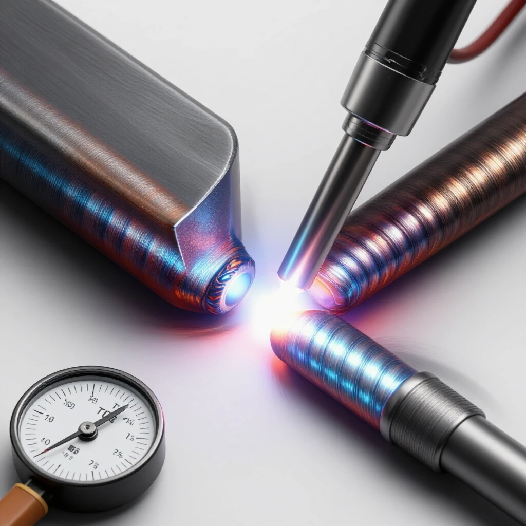
The Mechanics of Metal Fusion and Heat-Affected Zones
Fusion depth refers to the distance that the molten weld pool extends into the base metal. To create a structurally sound joint, the arc must melt the faces of both workpieces and the filler metal into a single, homogenous pool.
When we talk about the heat-affected zone (HAZ), we are referring to the area of the base metal that did not melt but had its microstructure and properties altered by the heat. If your heat input is too low, you won’t get deep enough into the metal, leading to a “cold” weld. Conversely, if you spend too much time trying to force depth with a low-amperage arc, you expand the HAZ, which can make the surrounding metal brittle and prone to cracking under stress.
Understanding Tensile Strength and Shear Stress
Tensile strength is the maximum amount of pulling stress a material can withstand before failing. Shear stress occurs when forces act parallel to the cross-section of the weld. If a weld only penetrates 20% of the material thickness, your joint is only as strong as that 20%. In a structural load path, the stress will concentrate at the root of the weld (the bottom). If that root isn’t fused, the stress has nowhere to go, leading to a brittle fracture.
| Material Type | Typical Yield Strength (PSI) | Common Structural Use |
|---|---|---|
| A36 Carbon Steel | 36,000 | General frames and brackets |
| 4130 Chromoly | 63,100 – 117,000 | Roll cages and aircraft tubing |
| 6061-T6 Aluminum | 35,000 – 40,000 | Lightweight structures |
| 304 Stainless Steel | 30,000 – 35,000 | Corrosion-resistant parts |
Calibrating Amperage for Deep Material Integration
Amperage is the primary driver of heat input in TIG welding. If your current is set too low, the arc will lack the energy required to liquify the base metal quickly. This results in the filler metal “balling up” on the surface rather than flowing into the root.
A reliable starting point for steel is approximately one ampere for every 0.001 inches of material thickness. For example, if you are working on 1/8-inch (0.125″) plate, you should set your machine to at least 125 amps. However, this is just a baseline. If you are welding a T-joint where the heat dissipates into two different directions, you may need to increase that by 10% to 20% to maintain a deep puddle.
The Impact of Current on the Weld Pool
When I diagnose a joint that failed to bite deep enough, the first thing I look at is the puddle behavior. A healthy puddle should look “wet” and slightly concave as it sinks into the metal. If the puddle looks convex or “frozen” around the edges, your amperage is likely too low. You aren’t just melting the surface; you are trying to create a molten bridge that spans the entire thickness of the joint.
- Increase amperage in 5-10 amp increments until the puddle forms within 2 to 3 seconds of arc initiation.
- Use a foot pedal to “punch” the heat at the start to establish a deep pool, then taper off as the base metal saturates with heat.
- Watch for the “sink”—the moment the surface tension of the molten metal breaks and it drops into the joint.
Managing Torch Geometry and Travel Speed
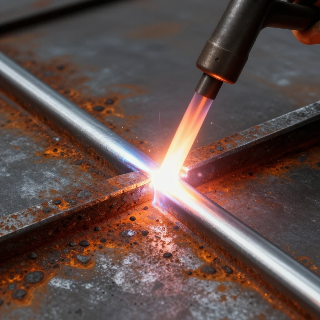
The angle at which you hold your torch dictates where the arc’s energy is focused. If your torch is tilted too far back (a high “push” angle), the arc energy is deflected across the surface of the metal rather than being driven downward.
For maximum depth, I aim for a torch angle of about 75 to 80 degrees relative to the workpiece. This “near-vertical” position ensures that the plasma stream of the arc is pushing directly into the root of the joint. If you lean the torch back to see the puddle better, you are sacrificing the force needed to achieve deep fusion.
Travel Speed and the Heat Saturation Paradox
Intermediate welders often move too slowly, thinking that more time spent in one spot will result in a deeper weld. In reality, moving too slowly creates a wide, shallow puddle because the heat spreads out laterally across the surface.
Interestingly, a slightly faster travel speed with higher amperage often results in deeper fusion. This is because the concentrated arc force stays ahead of the molten pool, allowing the arc to strike the “cold” metal at the bottom of the joint directly. If you move too slowly, you end up welding into a large pool of molten filler metal, which acts as a heat sink and prevents the arc from reaching the base metal.
- Maintain a tight arc length (roughly the diameter of your tungsten). A long arc spreads heat out and loses its “drilling” force.
- Coordinate your filler rod additions. Too much filler metal too fast will chill the puddle and stop it from sinking.
- Observe the “V” shape of the ripples. If they are very wide and flat, you are likely moving too slowly with insufficient heat.
Optimizing Electrode Preparation and Shielding Gas
The shape of your tungsten electrode acts like a nozzle for the arc. A sharp, pointed tungsten creates a narrow, focused arc that is excellent for pinpointing the root of a joint. A blunt or rounded tungsten creates a wide, diffused arc that is better for thin sheet metal but poor for thick structural joints.
I prefer a “truncated” tip—grind the tungsten to a sharp point, then lightly dull the very end. This prevents the tip from melting into the puddle while maintaining a tight arc cone. Always grind your tungsten lengthwise (parallel to the electrode) to ensure the electrons flow straight off the tip. Radial grind marks will cause the arc to wander and lose its concentration.
Shielding Gas Flow and Arc Stability
While argon shielding gas is primarily used to prevent oxidation, its flow rate affects arc stability. If your flow rate is too high (above 25 CFH in many cases), it can cause turbulence that cools the puddle or pushes it around, hindering depth.
For most shop projects, a flow rate of 15-20 CFH (Cubic Feet per Hour) is the “sweet spot.” If you are using a large gas lens, you can maintain better coverage at lower flow rates, which keeps the arc focused. If you notice the arc “fluttering,” check for drafts in the shop or a leak in your gas line, as an unstable arc cannot provide consistent heat.
- Select a 2% Lanthanated or Ceriated tungsten for all-around performance.
- Grind to a taper roughly 2 to 2.5 times the diameter of the electrode.
- Set gas flow to 17 CFH for a #7 or #8 cup.
Joint Preparation and the Role of the Root Gap
One of the most common mistakes I see in garage fabrication is trying to weld two thick pieces of metal that are butted tightly together with no bevel. Without a path for the arc to reach the bottom, you will only ever achieve “surface tension” fusion.
For any material thicker than 1/8 inch, you should consider a bevel or a root gap. A bevel involves grinding the edges of the metal to a 30-degree or 37.5-degree angle, creating a “V” shape when the pieces are joined. This allows you to place your first weld bead (the root pass) at the very bottom of the joint.
The Importance of the Root Opening
A root gap is a small space (usually 1/16″ to 3/32″) left between the two pieces of metal. This gap allows the arc to pass through the joint and melt the back side, ensuring 100% fusion through the entire thickness. In industrial pipe welding, this is a requirement. In a home shop, it is the best way to ensure your frame won’t fail.
| Material Thickness | Joint Prep Type | Recommended Gap |
|---|---|---|
| < 1/8″ (3mm) | Square Groove | 0 – 1/32″ |
| 1/8″ – 1/4″ (3-6mm) | Single V-Bevel | 1/16″ |
| > 1/4″ (6mm) | Single V-Bevel | 3/32″ – 1/8″ |
Troubleshooting Common Fusion Defects
When a weld fails to integrate properly, it usually leaves behind specific visual clues. Learning to read these clues is essential for adjusting your technique before the project is finished.
One major red flag is “cold lapping” or “overlap.” This occurs when the filler metal rolls over the edge of the weld bead without actually fusing to the base metal. It looks like a rounded edge rather than a smooth transition. This is almost always caused by low amperage or an arc that is too long.
Diagnostic Checklist for Weld Integrity
If you suspect your welds aren’t biting deep enough, perform a “quench and break” test on a piece of scrap material of the same thickness. Weld a T-joint, then use a sledgehammer to bend the vertical piece over the weld. If the weld snaps off and the base metal looks untouched underneath, you have a fusion problem.
- Check for “root suck-back,” where the weld is concave on the back side because the heat was too high or the filler was insufficient.
- Look for “lack of fusion” at the toes (the edges) of the weld, which indicates the torch wasn’t pointed at the side walls long enough.
- Verify that your metal is chemically clean. Mill scale, oil, and rust act as insulators, preventing the arc from making a deep connection.
Selecting the Correct Filler Metal
Using the wrong filler rod can lead to a weld that looks okay but lacks structural integrity. The filler rod should generally match the mechanical properties of the base metal. For common A36 or mild steel, ER70S-2 or ER70S-6 is the standard. The “70” stands for 70,000 PSI of tensile strength.
If you use a filler rod that is too thick for the job, it will act as a “heat sink.” Every time you dab a 1/8″ rod into a puddle on 1/16″ metal, you are sucking the heat out of the puddle. This causes the puddle to freeze prematurely, preventing it from sinking into the joint. Match your filler rod diameter to your material thickness or slightly smaller.
- For 1/8″ steel, use a 1/16″ or 3/32″ filler rod.
- Ensure the filler rod is cleaned with acetone to remove manufacturing oils.
- Keep the hot end of the filler rod within the gas shield to prevent contamination that can weaken the bond.
Case Study: The Suspension Link Failure
I once consulted on a custom off-road vehicle where the lower control arm mounts had failed. The fabricator had used a high-end TIG machine and the welds looked like “stacked dimes.” However, the mounts had “peeled” off the axle tube.
The issue was a combination of two factors: no beveling on the 1/4″ thick mounts and a travel speed that was too fast for the amperage used. The arc had only melted the very surface of the axle tube. Because the axle tube acted as a massive heat sink, the puddle never had a chance to “sink” in.
We corrected this by grinding a 45-degree bevel on the mounts and increasing the amperage from 180 to 220. We also pre-heated the axle tube to 250 degrees Fahrenheit using a propane torch. This reduced the “thermal shock” and allowed the TIG arc to achieve full-depth fusion with much less effort. The result was a joint that could withstand the high-impact forces of off-road racing.
Actionable Framework for Ensuring Deep Fusion
To prevent structural failures in your workshop, follow this systematic approach for every critical joint:
- Material Analysis: Identify the thickness and type of metal. Consult MatWeb for yield strength if the project is load-bearing.
- Edge Prep: Grind away all mill scale at least 1 inch back from the joint. If the metal is thicker than 1/8″, grind a bevel.
- Machine Setup: Set your amperage 10% higher than you think you need. You can always back off with the foot pedal, but you can’t add heat that isn’t there.
- Tack Welding: Place small, deep tacks every 2-3 inches to prevent the joint from opening up or “warping” as you weld.
- The Root Pass: Focus the arc entirely on the bottom of the “V” or the gap. Watch for the metal to melt and “bridge” before adding filler.
- Visual Inspection: Look at the back side of the joint. You should see a small “heat tint” or a slight bulge of metal, indicating the heat traveled all the way through.
Frequently Asked Questions
Why does my weld look like it’s sitting on top of the metal?
This is usually caused by insufficient heat (low amperage) or moving too fast. The base metal hasn’t reached its melting point, so the filler rod just sits on the surface. Increase your amperage and slow down until you see the puddle “wet out” into the base metal.
Can I fix a weld that has poor penetration by just welding over it?
No. Adding another layer of weld on top (capping) does not fix the lack of fusion at the root. You must grind out the original weld entirely, down to the base metal, and re-weld the joint with proper settings and preparation.
How does the arc length affect how deep the weld goes?
A shorter arc length (keeping the tungsten close to the metal) creates a more concentrated, high-pressure plasma stream. This “digs” into the metal more effectively. A long arc spreads out the energy, resulting in a wide, shallow, and weak weld.
Is it better to use a sharp or blunt tungsten for thick steel?
For deep fusion, use a sharp tungsten with a slightly flattened tip (truncated). This provides the best balance between a focused arc and electrode longevity. A very blunt tungsten will create a wide arc that struggles to reach the bottom of a V-groove.
Does cleaning the metal really affect how deep the weld goes?
Yes. Contaminants like mill scale (the dark gray flaky layer on hot-rolled steel) have a higher melting point than the steel itself. The arc will spend its energy trying to burn through the scale rather than melting the steel, leading to shallow fusion and inclusions.
How do I know if I’ve achieved full penetration on a butt joint?
The most reliable way is to look at the back side of the joint. You should see a consistent “bead” of metal that has pushed through. If you cannot see the back side, you must rely on your puddle observations—ensuring the puddle is sinking into the root gap during the weld.
What is the “Rule of Thumb” for TIG amperage on aluminum?
Aluminum is a massive heat sink. You typically need more initial amperage than steel—roughly 1.5 amps per 0.001″ of thickness. However, because aluminum conducts heat so well, you will need to back off the amperage significantly as the part heats up to avoid blowing a hole through it.
Why do my welds crack down the middle right after I finish?
This is often a “crater crack” or a “centerline crack.” It can be caused by a weld bead that is too thin or shallow to handle the shrinkage stresses as the metal cools. Increasing fusion depth and ensuring a proper bead profile (slightly convex) can help prevent this.
Should I use a “weaving” motion to get deeper fusion?
For the root pass, a straight “stringer” bead is usually better for depth. Weaving spreads the heat out over a wider area, which can actually decrease the depth of the weld. Save the weaving for the final cover passes if a wider bead is required.
Can a shielding gas leak cause shallow welds?
Yes. If air (oxygen and nitrogen) gets into the shielding gas, it can cause the arc to lose its focus and stability. This results in a “lazy” arc that doesn’t provide the concentrated heat necessary for deep material integration. Always check your O-rings and gas connections.
(This article was written by one of our staff writers, James Harlan. Visit our Meet the Team page to learn more about the author and their expertise.)