How to Measure Sheet Metal Bend Angles Accurately (DIY Fix)
I remember a Tuesday afternoon about eight years ago. I was working in a small custom shop, trying to diagnose why a series of heavy-gauge brackets were failing to align with the mounting holes on a chassis. We weren’t using high-end automation; we were using manual shop tools and a standard box-and-pan brake. The operator was frustrated, the client was waiting, and every part we checked seemed to vary by a degree or two. It wasn’t a material flaw or a lack of effort. It was a failure in our diagnostic process. We were guessing at the geometry instead of verifying it with a systematic approach.
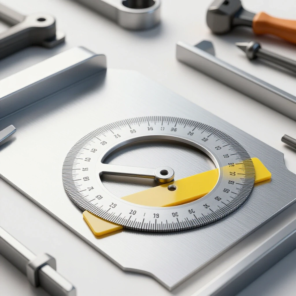
In my 15 years as a diagnostic specialist, I’ve learned that fabrication errors rarely have a single, “magic” cause. They are usually the result of small, compounding issues—a slightly loose pivot, a bit of debris under a workpiece, or a measurement tool that hasn’t been zeroed correctly. When you are trying to verify the precision of a folded part, you have to move away from “eyeballing” and toward a structured method of isolation and testing. This guide is built on the principles of mechanical troubleshooting to help you identify why your angles are off and how to confirm them with high accuracy using tools you already have.
Establishing High-Precision Baselines for Manual Bending
Establishing a baseline means creating a known “truth” in your shop environment before you start measuring. Without a verified reference point, any data you collect from your workpiece is essentially meaningless. This involves checking your surface plates, squares, and the floor itself to ensure they aren’t introducing hidden variables into your calculations.
Calibrating Manual Measurement Tools for Reliability
Calibration is the process of comparing a tool’s reading against a known standard to identify errors. For a fabricator, this means ensuring your protractors and squares are actually 90 degrees and that your digital levels are reading “zero” on a truly flat surface. It is the first step in any diagnostic path to prevent chasing “ghost” errors.
I always start by checking my combination square. I use the “flip test” on a straight edge: draw a line perpendicular to the edge, flip the square over, and see if the blade aligns with the line. If there is a gap of even 0.005 inches, your angular readings will be compromised. For digital inclinometers, I verify them against a precision machinist’s square sitting on a verified surface plate. If the digital readout says 90.2 degrees when pushed against a 90-degree square, I know I have a 0.2-degree offset that must be accounted for in every subsequent measurement.
Eliminating Workpiece Debris and Surface Interference
Surface interference refers to any physical obstruction, such as burrs, scale, or dust, that prevents a measurement tool from sitting flush against the metal. In a shop environment, these tiny particles can act like shims, tilting your protractor and giving you a false reading of the bend.
Before I ever put a tool to a flange, I hit the edges with a deburring tool or a fine file. A burr as small as 0.002 inches can throw an angle reading off by a quarter of a degree depending on the length of the tool’s arm. I also wipe down the workpiece and the measurement tool with a clean rag. It sounds basic, but in my experience, nearly 30% of “inaccurate” measurements are actually just tool-seating issues caused by shop grime or metal chips.
Systematic Verification of the Final Bend Angle
Once the workpiece is clean and the tools are calibrated, the focus shifts to the actual geometry of the part. Systematic verification involves taking multiple readings and comparing them to the intended design. This stage is where you isolate whether a problem is caused by the machine’s setup or by the way you are holding the tool.
Managing Springback Through Comparative Analysis
Springback is the tendency of metal to partially return to its original shape after the bending force is removed. To measure it accurately, you must compare the angle of the die or the brake’s position during the full stroke to the angle of the part after it is released.
I document this by measuring the “under-load” angle and then the “at-rest” angle. If I want a 90-degree bend and the part relaxes to 92 degrees, I have identified a 2-degree springback variable. By recording these deviations in a simple log, I can adjust my process. Troubleshooting this isn’t about guessing; it’s about knowing the exact degree of recovery for that specific setup. I use a digital inclinometer to find the difference, ensuring the base of the tool is parallel to the bend line to avoid skewed data.
Multi-Point Checking to Identify Twist and Bow
Multi-Point checking involves taking measurements at both ends and the center of a bend line to ensure the angle is consistent across the entire width of the part. This helps diagnose mechanical issues like “bowing” in the brake or uneven clamping pressure that causes the metal to twist.
If I measure 90 degrees on the left side and 91.5 degrees on the right, I’m not looking at a measurement error; I’m looking at a machine alignment fault. This 1.5-degree variance suggests that the upper die or the clamping leaf is not parallel to the bed. I use a systematic approach to check the pivot points for wear. Even 0.010 inches of play in a bushing can result in a noticeable angular deviation across a 24-inch workpiece.
| Measurement Method | Typical Accuracy | Best Use Case | Potential Pitfall |
|---|---|---|---|
| Manual Protractor | ±1.0° | Quick shop-floor checks | Parallax error (viewing angle) |
| Digital Inclinometer | ±0.1° | Verifying springback | Low battery or unlevel base |
| Sine-Bar Setup | ±0.01° | High-precision templates | Requires trigonometric math |
| Machinist Square | ±0.05° | Checking 90-degree corners | Light-gap interpretation |
Advanced Shop-Floor Diagnostics for Angular Errors
When standard measurements show a recurring error, you have to dig deeper into the mechanics of your tools. Advanced diagnostics involve looking for tool chatter, vibration, or mechanical backlash that might be shifting your workpiece during the bending process.
Identifying Tool Chatter and Vibration in Manual Brakes
Tool chatter in a manual brake isn’t a sound; it’s a physical vibration that occurs when the machine isn’t rigid enough to hold the metal steady. This vibration can cause the workpiece to “walk” or shift slightly before the bend is fully set, leading to inconsistent angles that are difficult to measure.
I check for this by looking at the surface of the bend. If I see “stutter” marks or uneven compression lines, I know the machine is vibrating. To fix this, I inspect the mounting bolts and the floor anchors. A machine that isn’t bolted down can develop resonant harmonics that interfere with the precision of the stroke. I use a smartphone vibration analyzer app to check the stability of the brake during a heavy pull. If the frequency spikes, it’s a sign that the frame is flexing, which will always compromise your ability to get a repeatable measurement.
Resolving Mechanical Backlash and Pivot Play
Backlash is the “dead space” or play in a mechanical system, often found in the gears or pivots of a bending tool. If your brake has backlash, the handle might move several degrees before the clamping leaf actually engages the metal, making it impossible to rely on the machine’s built-in scales.
I diagnose this by using a dial indicator. I set the indicator tip against the clamping leaf and slowly move the handle. If the handle moves 0.030 inches before the leaf moves, that is my backlash value. This play causes the metal to be held with inconsistent pressure, which directly affects the final angle. To resolve this, I tighten the gibs or replace worn brass bushings. Eliminating this “slop” ensures that when you measure a 45-degree angle, it is because the machine actually moved 45 degrees, not because it slipped.
Implementing the Sine-Bar Technique in the Workshop
When a project requires precision beyond what a standard protractor can provide, I turn to the sine-bar method. This is a classic millwright technique that uses a known length and basic trigonometry to set or verify an angle with extreme accuracy.
Geometric Logic for Precise Flange Verification
The sine-bar technique relies on the “Hypotenuse” of a triangle. By placing a bar of a known length (usually 5 or 10 inches) on a surface plate and propping up one end with a specific height, you create a perfect angle. You then place your bent part against this bar to see if it matches.
To calculate the height needed for a specific angle, I use the formula: Height = Sine(Angle) x Length of Bar. For example, if I need to verify a 30-degree bend using a 5-inch sine bar, the math is: 0.500 (Sine of 30°) x 5 = 2.500 inches. I stack gauge blocks or precision-ground spacers to exactly 2.500 inches. If the flange of my part sits perfectly flat against the bar with no light visible between them, I know my angle is exactly 30 degrees. This removes the “human element” of reading a dial or a digital screen.
Troubleshooting Alignment Faults with Sine-Bars
Using a sine bar also helps diagnose if a part has a “compound” error—where the bend is correct at the base but the flange is twisted. By moving the sine bar along the length of the bend, I can see if the gap changes.
If the gap increases as I move the bar, I’ve isolated a structural alignment fault in the brake. This is often caused by the “over-bending” of the center of the machine, a common issue in lighter-duty manual brakes. I record these gaps using feeler gauges. A gap of 0.004 inches over a 5-inch run might seem small, but it indicates a significant mechanical deflection that will cause assembly issues later.
Tracking and Documenting Diagnostic Data
Methodical troubleshooting requires a paper trail. If you don’t write down your measurements, you are just making educated guesses. I keep a dedicated log for every machine in the shop to track its performance over time.
Creating a Tool Calibration Checklist
A calibration checklist ensures that every measurement starts from a point of accuracy. I perform these checks at the start of every work week or before any high-precision job.
- Surface Plate Flatness: Clean with alcohol and check for nicks.
- Square Verification: Use the flip-test on all machinist squares.
- Digital Level Zeroing: Zero the inclinometer on a verified level surface, then rotate 180 degrees to check for consistency.
- Protractor Tension: Ensure the pivot nut is tight enough to hold the setting but loose enough to move smoothly.
- Feeler Gauge Integrity: Check that blades aren’t bent or rusted, which adds thickness.
Using a Fault-Tree for Angular Deviations
When a bend is out of tolerance, I use a fault-tree to quickly narrow down the cause. This prevents me from wasting time adjusting the machine when the problem might be a simple measurement error.
- Is the angle inconsistent across the bend?
- Yes: Check for machine flex, uneven clamping, or pivot wear.
- No: Proceed to springback analysis.
- Is the angle consistently off by the same amount?
- Yes: Adjust the machine’s stop-block or account for springback.
- No: Check for debris under the part or tool calibration errors.
- Does the angle change when the part is moved?
- Yes: Check for “bow” in the material or the brake leaf.
- No: The issue is likely the initial setup or die alignment.
Practical Steps for High-Accuracy Shop Fixes
Once you have diagnosed the root cause of an angular error, you need to implement a permanent fix. These aren’t “hacks”; they are standard mechanical adjustments designed to return your equipment to its peak operating condition.
Adjusting for Backlash in Manual Equipment
If you’ve identified backlash in your bending brake, the fix usually involves the adjustment of tensioning bolts or the replacement of shim stock. Most manual brakes have adjustable “gibs”—metal strips that take up the play between moving parts.
I tighten the gib screws in small increments—usually 1/8th of a turn at a time. After each adjustment, I move the machine through its full range of motion. If it starts to bind, I’ve gone too far. The goal is to reach a point where the dial indicator shows less than 0.002 inches of movement before the clamping leaf engages. This level of precision ensures that your measurements are repeatable, part after part.
Dampening Resonant Vibrations
If your diagnostics pointed toward vibration or tool chatter, you need to increase the mass or the rigidity of your setup. For a manual brake, this often means adding a stiffener bar to the clamping leaf.
I’ve seen shops weld a piece of heavy angle iron to the back of a leaf to prevent it from bowing during a bend. While this changes the machine’s weight, it significantly reduces the “spring” in the metal. When the machine is rigid, the metal is forced to follow the geometry of the tool exactly, making your manual measurements much more reliable. I always re-verify the machine’s level after adding any significant weight to ensure the frame hasn’t shifted.
Conclusion: The Path to Precision
Accurate measurement in a manual shop isn’t about having the most expensive tools; it’s about having the most disciplined process. By treating every angular error as a diagnostic puzzle, you move away from the frustration of scrap metal and toward the satisfaction of a perfect fit.
I’ve found that the best fabricators are the ones who stop and ask “why” when a measurement is off by half a degree. They check their tools, they clean their surfaces, and they account for the mechanical quirks of their machinery. Use the sine-bar for your critical work, keep your digital levels calibrated, and never ignore a burr or a bit of shop grime. These small steps are what separate a hobbyist from a master diagnostic specialist.
Frequently Asked Questions
How do I know if my digital inclinometer is accurate enough for sheet metal work? Most digital inclinometers are accurate to ±0.1 or ±0.2 degrees. For general fabrication, this is excellent. However, you must verify it by “zeroing” it on a known level surface. If you flip the tool 180 degrees and the reading changes by more than 0.1 degrees, the tool needs recalibration or the internal sensor is failing.
Why does my protractor give different readings at different spots on the same bend? This is usually caused by “bowing” in the brake or the material. If the center of the bend is wider than the ends, the clamping pressure is likely uneven. It can also be caused by small burrs on the edge of the metal that tilt the protractor. Always deburr your parts before measuring.
Can I use a standard plastic protractor from a hardware store? I don’t recommend it for professional work. Plastic protractors flex and the markings are often thick, leading to parallax errors. A stainless steel machinist’s protractor or a digital version provides the rigidity needed to sit flat against the metal, which is essential for a ±0.5-degree tolerance.
What is the “light-gap” method? This is a diagnostic technique where you place a machinist square against a bend and look for light passing through the join. If you see light at the tip of the square, the angle is “over-bent” (less than 90°). If you see light at the corner, it is “under-bent” (more than 90°). You can use feeler gauges to measure the gap and calculate the exact error.
How do I account for the thickness of the metal when using a sine bar? You should always measure the “inside” angle or the “outside” angle consistently. When using a sine bar, I prefer measuring the outside flange. Ensure the bar is long enough to span the flat section of the flange without hitting the radius of the bend, as the radius will throw off your geometric calculation.
What is the most common mistake when measuring bent angles? The most common mistake is not holding the tool perpendicular to the bend line. If the tool is tilted even slightly to the side, it creates a “swept” angle measurement which will always be larger than the actual bend angle. I use a small block of wood or a magnetic guide to keep my protractor perfectly square to the fold.
How often should I calibrate my shop squares? In a busy shop, I check my primary squares once a month. If a square is dropped, it must be checked immediately. Even a fall of two feet onto a concrete floor can knock a precision square out of alignment by several thousandths of an inch.
Does temperature affect my angle measurements? While thermal expansion affects the length of the metal, it rarely changes the angle significantly in a standard shop environment. However, extreme cold can make some digital displays sluggish or inaccurate. Always let your electronic tools reach shop temperature before trusting their readings.
What should I do if my brake is “twisting” the parts? Check the pivot bushings. If one side is more worn than the other, that side will engage later, causing a twist. You can sometimes “shim” the die or the clamping leaf to compensate, but the permanent fix is replacing the worn mechanical components.
How can I measure an angle that is greater than 180 degrees? This is essentially a “return bend.” I measure the supplementary angle (the “closed” part) and subtract it from 180. For example, if the internal gap measures 30 degrees, the bend itself is 150 degrees. Using a digital inclinometer makes this easier by allowing you to “zero” on one flange and move to the next.
(This article was written by one of our staff writers, Paul Whitaker. Visit our Meet the Team page to learn more about the author and their expertise.)