Installing a Budget Copper Air Pipe Dryer System (DIY Plan)
I remember standing over a bench in my early years, staring at a series of TIG welds on a stainless manifold that looked like Swiss cheese. I had checked my shielding gas three times, swapped the tungsten, and even cleaned the base metal with acetone until the rag came away white. Nothing worked. It wasn’t until I noticed a tiny bead of water on the tip of my air-powered die grinder that the lightbulb went on. The moisture from my shop’s poorly managed air lines was being sprayed directly onto the joint during prep, causing instant contamination.
That experience taught me that in a fabrication shop, your air supply is just as critical as your power supply. When we talk about a metalworking diagnostic guide, we often focus on the machines themselves, but the infrastructure connecting them is frequently the root cause of intermittent failures. Over my 15 years as a diagnostic specialist, I’ve found that building a reliable, shop-made moisture removal network using copper tubing is one of the most effective ways to stabilize a production environment. It isn’t just about dry air; it’s about eliminating the variables that lead to tool chatter, surface defects, and equipment downtime.
Identifying the Root Cause of Compressed Air Contamination
Moisture in compressed air is a byproduct of physics that occurs when air is compressed and then cooled, forcing water vapor to condense into liquid. In a fabrication setting, this liquid travels through lines, washing away tool lubricants and contaminating weld zones. Identifying this issue involves observing “spitting” tools, flash rust on internal components, or unexpected porosity in your beads.
When you compress air, you generate heat. As that hot air moves through your shop lines, it cools down. Since cool air cannot hold as much water vapor as warm air, the water drops out of suspension. If your lines are a short run of rubber hose, that water goes straight into your plasma cutter or air-powered sander. To solve this, we use a systematic isolation approach. We need to create a “heat sink” that forces this condensation to happen in a controlled area where we can drain it, rather than at the tool.
I use a simple test to confirm if air quality is the culprit for shop issues. Take a clean piece of cardboard and hold it six inches away from an air nozzle. Run the air for 30 seconds. If you see even a single damp spot, your system is compromised. This moisture leads to what we call “slugging,” where pockets of water hit a tool’s internal vanes, causing momentary drops in RPM. These drops are a primary cause of tool chatter solutions being ineffective because the source isn’t the tool’s rigidity, but its power consistency.
Designing a Thermal Exchange Network for Shop Efficiency
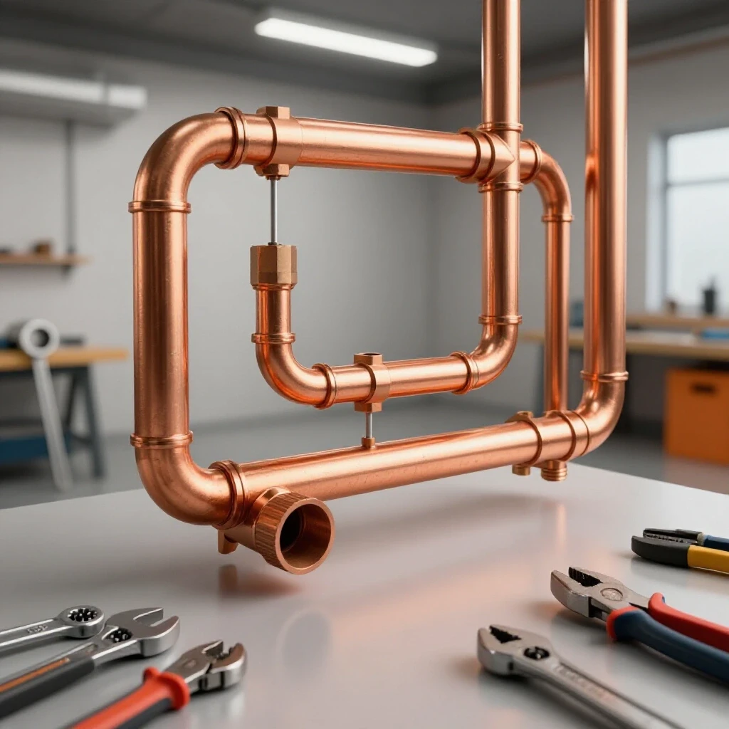
A thermal exchange network uses the high thermal conductivity of copper to rapidly drop the air temperature and force moisture to condense. By routing the air through a series of vertical “up-and-down” runs, we use gravity to trap the liquid in drop legs while the dried air continues to the outlet. This structural alignment of the pipes is key to a passive, low-maintenance drying solution.
Copper is the ideal material here because its thermal conductivity is roughly 20 times higher than that of stainless steel. This means it pulls heat out of the air much faster. When I design these for small to mid-sized shops, I follow a specific mechanical troubleshooting step: the “zig-zag” or “ladder” layout.
- Vertical Runs: Use at least 50 feet of copper tubing arranged in vertical segments.
- Gravity Drains: Every vertical drop must end in a “T” fitting with a manual ball valve at the bottom.
- Air Flow Direction: Always feed the air into the top of a segment and take it out of the top of the next to ensure liquid stays at the bottom.
Building this requires a basic understanding of plumbing tolerances. For example, when soldering 3/4-inch L-type copper, you want a capillary gap of about 0.002 to 0.005 inches between the pipe and the fitting. If the fit is too loose, the joint will fail under the vibration of the compressor. I always recommend using a “closed-loop” or “trunk and branch” layout to maintain consistent pressure (PSI) across the entire shop, which prevents the pressure drops that lead to motor controller faults in larger equipment.
Troubleshooting Weld Porosity Through Air Quality Control
Weld porosity occurs when gas pockets are trapped in the weld pool, often caused by moisture on the metal surface or contaminated shielding gas. In shops using pneumatic prep tools, water droplets from the air line can contaminate the weld zone long before the arc is even struck. Systematic isolation of the air supply is the first step in resolving these defects.
In my experience, troubleshooters often blame the welder when the issue is actually the prep tool. If you use an air grinder to prep a V-groove, and your air line is “wet,” you are essentially tattooing water molecules into the grain of the steel. When you strike an arc, that water flashes into hydrogen and oxygen. The hydrogen, in particular, is a nightmare for high-strength steels, leading to hydrogen-induced cracking.
| Symptom | Probable Cause | Diagnostic Test |
|---|---|---|
| Pinholes in weld bead | Surface moisture from air tools | Swap to electric grinder for one test joint |
| Erratic plasma arc | Water in the torch head | Check consumable for “pitting” or blue discoloration |
| Inconsistent bead width | Air pressure fluctuations | Install a dedicated gauge at the drop leg |
| Flash rust on prepped joints | High humidity in air lines | Wipe joint with a clean, dry white cloth |
By implementing a copper manifold, you provide a consistent environment. I’ve seen weld defect rates drop by 40% just by switching from a standard rubber hose setup to a dedicated copper drying rack. This is a classic example of how metal fabrication fixes often require looking upstream from the actual point of failure.
Eliminating Tool Chatter and Vibrational Wear in Pneumatic Systems
Tool chatter in air-driven grinders or sanders often stems from inconsistent pressure or internal corrosion caused by water. When moisture strips away lubrication, internal bearings develop play, leading to resonant harmonics that ruin surface finishes. A dry air supply ensures stable tool RPM and extends the lifespan of precision components.
When a pneumatic tool chatters, the instinct is to press harder. This is a mistake. In my diagnostic logs, I’ve noted that tool chatter is often a result of “surging.” As water enters the tool, it creates a momentary resistance, slowing the motor. As the water clears, the motor speeds back up. This cycle creates a harmonic vibration that is transferred to the workpiece.
To resolve this, we look at the mechanical tolerances of the tool. A typical high-speed air grinder might have a spindle backlash of less than 0.001 inches. Once water causes corrosion on the bearing races, that play can jump to 0.005 inches, which is enough to cause visible “scalloping” on a finished surface. By using a copper-based cooling system, you ensure that the air reaching the tool is at room temperature and dry, allowing the tool’s lubricant to do its job.
- Check RPM Stability: Use a digital tachometer to see if the tool stays within +/- 50 RPM under no-load.
- Inspect Exhaust: If the tool exhaust is misty, your drying system is overwhelmed or your drain legs are full.
- Vibration Analysis: Use a smartphone vibration spectrum analyzer app. If you see spikes at low frequencies, it’s likely a mechanical imbalance from moisture-driven corrosion.
Strategic Layout and Drainage for Workshop Air Distribution
A successful air distribution layout relies on gravity and thermal transfer to isolate contaminants. By installing drop legs with manual or automatic drains at the lowest points of the copper network, you ensure that liquid water is captured before it enters the tool lead. This structural alignment is critical for long-term system reliability.
The most common mistake I see in shop layouts is “downward sloping” lines that feed directly into tools. My lathe alignment checklist always includes checking the air lines if the machine uses a pneumatic chuck. If the lines slope toward the machine, you are feeding it a steady diet of water. Instead, your main header pipe should slope slightly away from the compressor—about 1 inch for every 10 feet of pipe.
The “drops” for your tools should always come off the top of the main header. This ensures that any liquid water running along the bottom of the pipe continues past the drop and falls into a dedicated drain leg at the end of the run. I recommend using 3/4-inch copper for the main trunk to minimize friction loss, and 1/2-inch for the vertical drops.
- Drain Frequency: In a humid shop, I drain my drop legs every 4 hours of compressor run time.
- Pressure Testing: Once the copper is soldered, I pressure test the system at 150 PSI using soapy water on every joint. A leak as small as 0.005 inches can cause your compressor to cycle unnecessarily, leading to heat buildup and even more moisture.
Diagnosing Mechanical and Electrical Component Failures
In advanced fabrication setups, air isn’t just for hand tools; it powers solenoids, actuators, and cooling systems. When moisture enters these components, it can cause “stiction”—a state where a valve is stuck until a certain pressure is reached, then it snaps open. This leads to timing errors in automated systems and can even cause back-EMF faults if a solenoid coil stays energized for too long while trying to move a stuck plunger.
Electrical diagnostic readings on these solenoids can be telling. If a 24V DC solenoid is drawing more than its rated amperage (usually around 0.5 to 1.0 Amps), it’s often fighting internal friction caused by scale and water. I’ve spent days chasing “ghost” errors in a motor controller only to find that a moisture-clogged air valve was causing a mechanical delay that the computer interpreted as an electrical fault.
To maintain these systems, I use a systematic diagnostic methodology: 1. Observation: Watch the actuator movement. Is it smooth or jerky? 2. Isolation: Disconnect the air line and check for liquid. 3. Measurement: Check the resistance (Ohms) of the solenoid coil. Compare it to the manufacturer’s spec (usually 20-60 Ohms). 4. Verification: After cleaning the air supply with the copper dryer, re-test the cycle time.
Case Study: The Porous Aluminum Nightmare
I once consulted for a shop that was failing 30% of its aluminum TIG welds. They were using a high-end inverter welder, and their lathe alignment checklist was perfect for the parts they were machining. Yet, the welds were full of black specks and bubbles. We spent two days checking the argon purity and the filler rod batch numbers.
The breakthrough came when I looked at their air system. They had a massive compressor, but the lines were just 100 feet of black iron pipe running along a cold exterior wall. The air was cooling so fast that it was turning into a literal stream of water inside the pipe. They were using an air-powered wire brush to “clean” the aluminum. The brush was actually driving moisture into the porous surface of the aluminum.
We spent a weekend installing a 60-foot copper ladder manifold with five drop legs. The total cost was less than the price of the wasted aluminum from the previous week. Once the air was dry, the porosity disappeared instantly. This case study highlights that a systematic approach to shop infrastructure is often more valuable than buying a more expensive welding machine.
Actionable Tracking and Maintenance Framework
To keep your air quality from degrading, you need a routine. I treat my air system like a machine tool. It requires calibration and inspection. If you don’t manage the “variable control” of your air, you’ll never have a stable fabrication process.
- Daily: Drain all drop legs and the compressor tank. Note if the volume of water increases, which could indicate a failing compressor pump (running hotter than usual).
- Monthly: Inspect copper joints for “green” oxidation, which indicates a pinhole leak.
- Quarterly: Check the pressure drop from the compressor tank to the furthest tool. If the drop is more than 10 PSI, you may have a restriction or a clogged filter.
- Annually: Replace any rubber “whip” hoses. Rubber degrades internally and can send small particles into your dry copper system, clogging the very tools you’re trying to protect.
Technical Benchmarks for System Health
- Max Pressure Drop: < 5 PSI across the manifold.
- Temperature Differential: Air at the tool should be within 10 degrees of ambient shop temperature.
- Solder Integrity: No visible “solder icicles” inside the pipe (which cause turbulence).
- Leak Rate: System should hold 120 PSI for 24 hours with less than a 2 PSI loss.
By following these mechanical troubleshooting steps, you move from guesswork to precision. You stop asking “why is my weld bubbling?” and start knowing that your prep environment is clean. This level of control is what separates an intermediate fabricator from a master of the craft.
FAQ: Managing Shop Air and Fabrication Defects
How does copper tubing help with troubleshooting weld porosity? Copper acts as a highly efficient heat exchanger. By cooling the compressed air quickly, it forces moisture to condense into liquid in the pipe rather than on your workpiece. Since moisture is a primary cause of hydrogen porosity in welds, using a copper manifold ensures your air-prepped joints stay dry and chemically stable for welding.
Can a copper air system reduce tool chatter in my grinders? Yes. Tool chatter is often caused by “slugs” of water hitting the internal vanes of an air motor, causing the RPM to fluctuate. These fluctuations create harmonic vibrations that transfer to the tool bit. A dry copper system provides a steady, consistent air stream, which stabilizes the tool’s rotational speed and eliminates moisture-induced vibration.
What is the ideal pipe diameter for a shop-built air dryer? For most shops, 3/4-inch L-type copper is the standard for the main cooling manifold. It provides enough surface area for cooling without causing a significant pressure drop. Using 1/2-inch for the final “drops” to your tools is acceptable, as long as the main header is large enough to act as a reservoir.
How do I know if my air system is causing my plasma cutter to fail? Look at your plasma consumables. If the electrode has a deep “pit” or the nozzle has black carbon tracking after only a few minutes of use, you likely have water or oil in your lines. A copper drying rack will trap this moisture before it reaches the torch, significantly extending the life of your consumables and improving cut squareness.
Why should I use copper instead of PVC or black iron pipe? PVC is dangerous; it can shatter under pressure and does not dissipate heat. Black iron pipe is prone to internal rusting, which sends grit into your tools. Copper is safe, does not rust, and has the high thermal conductivity required to actually cool the air and remove moisture effectively.
What is the “up-and-over” method in air line plumbing? This is a diagnostic layout where air is pulled from the top of the main header pipe. This ensures that any liquid water or heavy contaminants staying at the bottom of the pipe are not sucked into the tool drop. It’s a simple mechanical alignment trick that uses gravity to improve air quality.
How many vertical runs do I need for an effective cooling manifold? I recommend at least four to six vertical runs, each about 5 to 10 feet tall. This gives the air enough “dwell time” against the cool copper walls to drop its temperature below the dew point, ensuring maximum moisture separation before the air reaches your tools.
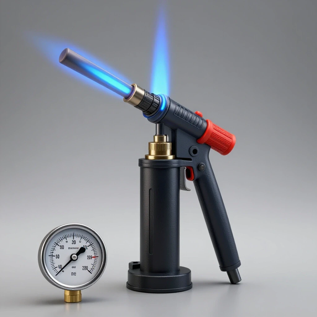
Does a copper dryer require any specialized tools to install? You will need basic copper plumbing tools: a pipe cutter, a deburring tool, a propane torch, and lead-free solder. The key is to ensure every joint is cleaned and fluxed properly to maintain a mechanical tolerance that can handle the vibration and pressure cycles of a shop compressor.
How do I test for leaks in my new copper air network? The best method is a static pressure test. Pump the system to its maximum working pressure (usually 125-150 PSI) and leave it overnight. A drop of more than 2-3 PSI indicates a leak. You can find the exact location by spraying a mixture of dish soap and water on the joints; bubbles will form even at very small leak sites.
Can moisture in air lines affect my lathe or mill? Absolutely. Many modern lathes use pneumatic cylinders for tool changers or chucking. Moisture can cause these cylinders to stick or move slowly, leading to timing errors or “stiction.” A dry air supply ensures these mechanical components move with the precision required for high-tolerance machining.
(This article was written by one of our staff writers, Paul Whitaker. Visit our Meet the Team page to learn more about the author and their expertise.)