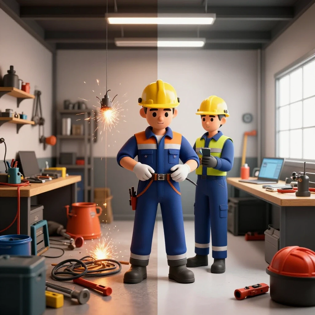
Hardened Dowel Pins vs Regular Bolts for Welding Jigs (Fix)
I remember standing over a heavy-duty chassis jig at 2:00 AM, staring at a stack of rejected frame rails. Every measurement was off by nearly a sixteenth of an inch, yet the jig looked perfectly solid. I had spent hours checking the welder settings and gas flow, thinking I was dealing with a standard case of thermal distortion. It wasn’t until I put a dial indicator on the main upright and gave it a firm shove that I saw the needle jump. The jig wasn’t holding its position because I had relied on threaded fasteners to do a job they weren’t designed for.
In the world of precision metalworking, the difference between a tool that works and one that fails often comes down to how we handle lateral forces. When you are troubleshooting alignment issues in a fabrication shop, you have to look past what is holding the parts down and start looking at what is keeping them from shifting. This is where the choice between specialized positioning components and standard hardware becomes a critical diagnostic factor.
Establishing a Systematic Diagnostic Framework for Fixture Accuracy
A systematic diagnostic framework is a step-by-step process used to isolate movement within a mechanical assembly by checking each connection point for play. It involves using precision measuring tools to verify that a fixture returns to the exact same “zero” point after every cycle.
When I start a metalworking diagnostic guide for a failing jig, I always begin with the “push test.” I set up a digital dial indicator against a critical surface of the jig and apply a measured amount of force. If the needle doesn’t return to zero, the assembly has internal “slop.” In many cases, this slop comes from the clearance gap required for threads to function.
Building on this, we have to look at the three primary variables of jig stability: 1. The tolerance of the locating holes. 2. The shear strength of the vertical components. 3. The repeatability of the part placement.
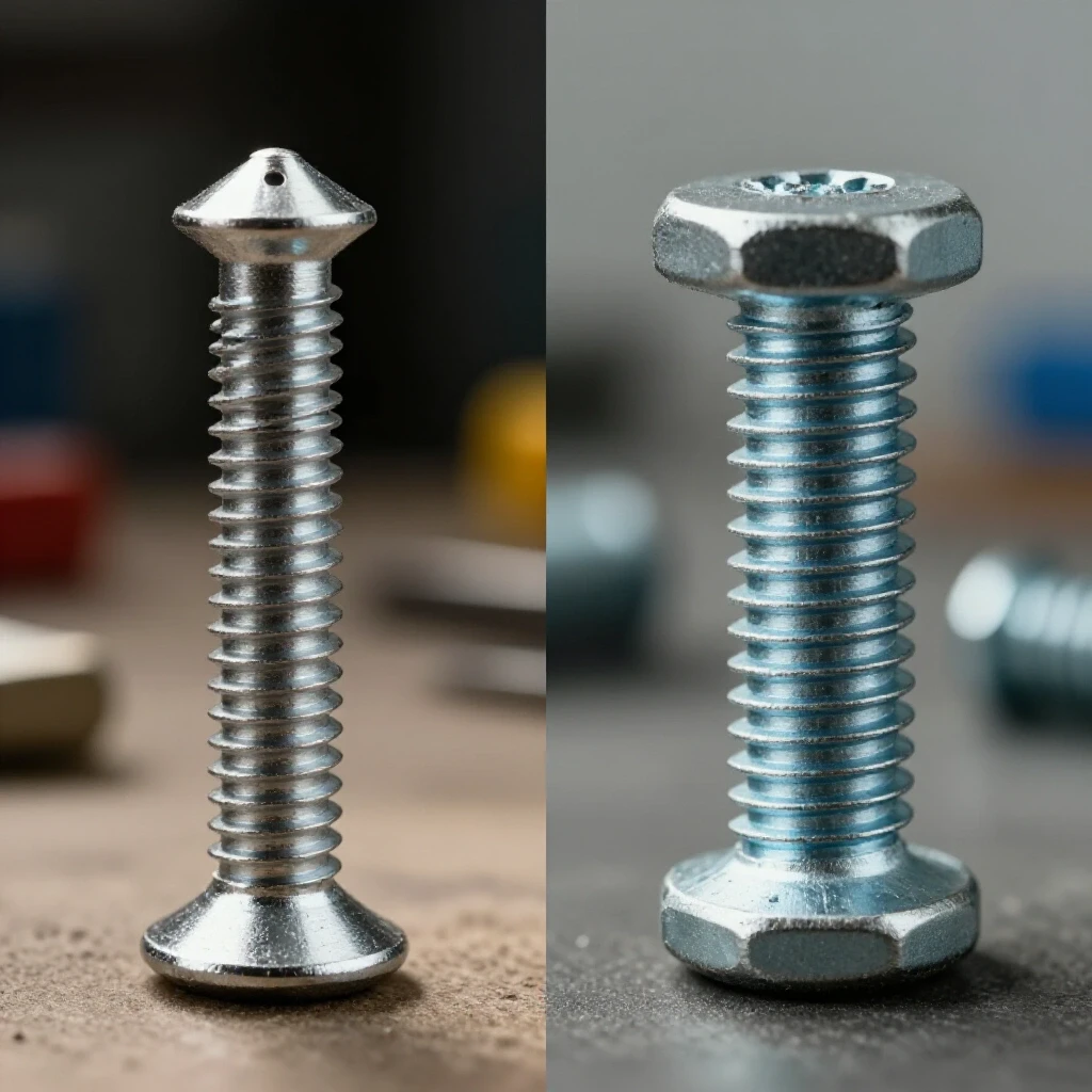
If you are using threaded hardware for positioning, you are fighting a losing battle against physics. A standard 1/2-inch bolt actually measures slightly less than its nominal diameter, and the hole it goes into is usually 1/32-inch larger. This creates a zone of uncertainty that makes precise mechanical troubleshooting steps nearly impossible to follow consistently.
Why Precision Locating Components Outperform Threaded Fasteners in Shear Applications
Precision locating components are solid, ground cylinders designed for interference fits that eliminate all radial movement between two plates. Unlike threaded hardware, these components are engineered to absorb lateral loads without shifting, providing a rigid baseline for any metal fabrication fixes.
The main issue with using bolts in a jig is that they are designed to provide clamping force, not positioning accuracy. When you tighten a bolt, you are pulling two surfaces together. The only thing keeping those surfaces from sliding sideways is the friction between them. In a welding environment, where heat causes metal to expand and contract with significant force, that friction is often overcome.
- Interference Fits: These offer a “zero-clearance” connection, usually requiring a press or a hammer to install, which removes any room for the part to wiggle.
- Surface Hardness: These components are through-hardened, meaning they won’t deform or “egg out” the holes when subjected to heavy shear loads.
- Ground Finishes: The outer diameter is typically ground to a tolerance of +0.0002/-0.0000 inches, ensuring a predictable fit every time.
Interestingly, when I transition a shop from bolts to hardened pins, the most common feedback I get is that their tool chatter solutions suddenly become more effective. A rigid jig dampens the vibrations that otherwise travel through the workpiece and into the cutting tool or welding arc.
Diagnosing Structural Alignment Faults in Heavy-Duty Welding Jigs
Structural alignment faults occur when the internal components of a jig shift out of square due to mechanical stress or thermal cycles. Diagnosing these faults requires mapping the “drift” of the jig over a series of work cycles to see if the error is random or cumulative.
In my 15 years of experience, I’ve found that “creeping” errors are almost always linked to threaded fasteners. As the jig heats up during welding, the metal expands. If the components are held by bolts in clearance holes, the expansion pushes the parts to the outer limit of that clearance. When the metal cools, it doesn’t always pull back to the original center. It stays at the edge of the hole.
To diagnose this, I use a simple tracking log: 1. Measure the jig at room temperature (Cold Baseline). 2. Run three full welding cycles. 3. Measure the jig immediately after the third cycle (Hot State). 4. Measure again after four hours of cooling (Recovery State).
If the Recovery State does not match the Cold Baseline within 0.002 inches, the jig is physically shifting. This is a clear indicator that you need to replace your threaded positioning points with ground, hardened pins that utilize an interference fit.
How Mechanical Troubleshooting Steps Isolate Root Causes of Misalignment
Mechanical troubleshooting steps involve a process of elimination where you lock down one variable at a time to see which part of the system is failing. It moves from the foundation of the machine or jig upward to the point of contact with the workpiece.
When I’m called in to fix a “mystery” alignment issue, I start at the floor. Is the table level? Are the legs bolted down? Once the foundation is verified, I move to the sub-plates. This is where I often find the culprit. If the sub-plates are held together with bolts alone, I can almost guarantee that the vibration from nearby machinery or the stress of clamping is causing micro-shifts.
- Check for “Bore Egging”: Remove the bolts and inspect the holes. If they are no longer perfectly round, the bolts have been hammering against the sides.
- Verify Thread Integrity: Look for “shaved” threads, which indicate the bolt has been sliding under load.
- Test for Backlash: Use a pry bar to see if you can move a component while it is supposedly “locked” down.
As a result of these tests, you can usually see exactly where the movement is happening. A bolt can provide thousands of pounds of clamping force, but it has almost zero resistance to “side-loading” compared to a press-fitted pin.
Troubleshooting Weld Porosity and Its Link to Jig Stability
Weld porosity is a defect characterized by small gas pockets trapped in the weld metal, often caused by contamination or inconsistent arc length. While often seen as a gas or material issue, it can also be triggered by jig vibrations that disturb the shielding gas envelope.
You might wonder how a choice of fasteners affects weld quality. It comes down to harmonics. If a jig is not perfectly rigid, it can develop a resonant vibration—essentially a high-frequency hum—caused by the cooling fans in the welder or the movement of the robot arm. This vibration can be enough to “flick” the shielding gas away from the weld pool for a fraction of a second.
Building on this, I’ve seen cases where tool chatter solutions and weld porosity fixes were the same thing: stiffening the jig. By replacing bolts with hardened pins, we eliminated the micro-vibrations. The result was a steadier arc and a more consistent gas shield.
| Diagnostic Factor | Threaded Bolt Setup | Hardened Pin Setup |
|---|---|---|
| Positional Accuracy | 0.015″ – 0.030″ | 0.0005″ – 0.001″ |
| Shear Load Capacity | Low (relies on friction) | High (relies on material strength) |
| Thermal Stability | Poor (shifts in clearance) | Excellent (interference fit) |
| Vibration Dampening | Low (components can rattle) | High (solid mechanical bond) |
| Repeatability | Decays over time | Remains constant |
The Role of Interference Fits in Eliminating Lathe Alignment Checklist Errors
An interference fit is a fastening method where the internal component is slightly larger than the hole it is entering, creating a friction-locked bond that requires force to assemble. This method is the gold standard for ensuring that two pieces of metal cannot move independently of each other.
When I work through a lathe alignment checklist, I am looking for any source of “runout” or “wobble.” If the headstock or the tailstock isn’t pinned to the bed, the vibration of a heavy cut can actually knock the machine out of alignment. I’ve seen lathes where the operator was constantly fighting a taper in their parts. They would adjust the bolts, get it straight, and three days later, the taper was back.
The fix was always the same: drill and ream for hardened pins once the alignment was perfect. Once those pins are in, the bolts only have to hold the parts down. The pins handle the “memory” of the machine. This is a fundamental concept in any metalworking diagnostic guide: use bolts for tension, use pins for position.
Practical Steps for Executing Metal Fabrication Fixes on Failing Jigs
Executing metal fabrication fixes requires a transition from temporary or “adjustable” setups to permanent, rigid assemblies. This process involves reaming existing holes to a precise size to accept hardened positioning components.
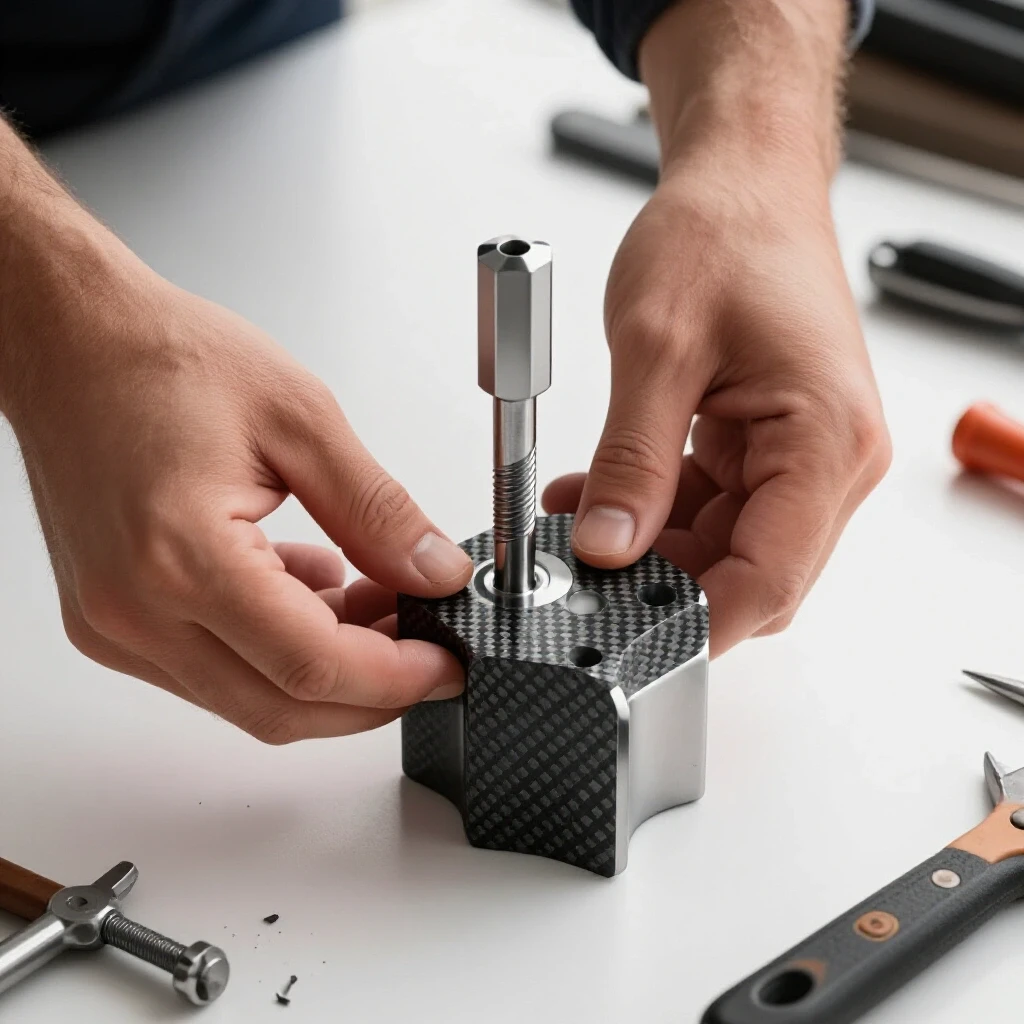
If you have a jig that is currently underperforming, you don’t necessarily have to scrap it. I often perform “field surgery” on jigs by following these steps: 1. Zero the Assembly: Use your dial indicators to get the jig into the exact position required. 2. Clamp it Down: Use heavy C-clamps or welding clamps to ensure it cannot move. 3. Match-Drill: Drill a hole through both plates that is roughly 1/64-inch smaller than your final pin size. 4. Ream to Size: Use a precision reamer to bring the hole to the exact diameter for a press fit (e.g., 0.4995 inches for a 0.5000-inch pin). 5. Press the Pin: Drive the hardened pin home.
By doing this, you have effectively “locked” the accuracy of that jig into the metal itself. The bolts can now be tightened without the fear that they will pull the part out of alignment as they seat.
Identifying and Resolving Tool Chatter Solutions Through Jig Rigidity
Tool chatter is a self-excited vibration that occurs when the cutting tool and the workpiece bounce against each other at a high frequency. Resolving this often requires increasing the mass or the stiffness of the work-holding fixture to shift the resonant frequency.
I once worked with a shop that was breaking carbide end mills every two hours while machining a fixture plate. They thought it was a spindle backlash issue. We checked the spindle and found it was within 0.001 inches of factory spec. The problem was actually the fixture. It was bolted to the table, but it wasn’t pinned.
Under the load of the cut, the fixture was microscopicly sliding back and forth within the bolt hole clearance. This created a “harmonic” that matched the tool’s rotation speed. As soon as we added two 5/8-inch hardened dowels to the setup, the chatter vanished. The machine sounded different—deeper and more solid.
Common Mechanical Troubleshooting Steps for Machine Re-alignment
Machine re-alignment is the process of restoring the geometric relationship between different moving parts of a machine tool, such as the squareness of a mill head to the table. This process relies on a “master” reference point that does not change.
- Clean all surfaces: Even a single metal chip (0.005 inches thick) can ruin an alignment.
- Check for burrs: Use a fine stone to ensure the mounting faces are perfectly flat.
- Indicate the “Fixed” Member: Find the part of the machine that doesn’t move and use it as your zero.
- Sweep the “Moving” Member: Use a dial indicator to check for parallelism.
- Pin the Location: Once the indicator reads zero across the entire travel, install your hardened pins.
In my experience, skipping step 5 is why people have to repeat steps 1 through 4 every month. A machine that is only held by bolts is a machine that is waiting to move.
Technical Data: Tolerance and Fit Standards for Positioning
To master these metal fabrication fixes, you need to understand the numbers. A “Slip Fit” is used when you need to remove the pin frequently, while a “Press Fit” is for permanent location.
- Slip Fit (H7/g6): The pin is roughly 0.0005 inches smaller than the hole.
- Press Fit (P7/h6): The pin is roughly 0.0005 to 0.001 inches larger than the hole.
- Bolt Clearance (Standard): The hole is typically 0.03125 inches larger than the bolt.
When you look at those numbers, it becomes obvious why bolts fail at positioning. A standard bolt hole has 30 times more room for error than a slip-fit pin. If your tolerance requirement is 0.005 inches, you simply cannot achieve it with a bolt in a standard clearance hole.
Case Study: The 50-Foot Frame Rail Alignment
I was once tasked with troubleshooting a structural alignment fault on a 50-foot trailer jig. The customer was complaining that the trailers were “dog-tracking”—meaning they didn’t pull straight down the road. We spent three days checking the axles, the tires, and the hitch. Everything was fine.
Finally, I went to the main assembly jig. It was a massive steel structure, all bolted together so it could be shipped in pieces. I set up a laser tracker and found that the jig was “bowed” by nearly an inch in the middle. The bolts had slipped during the heat of the first few dozen welds, and the whole jig had taken a permanent set in the wrong direction.
We had to pull the jig straight with hydraulic jacks, then we match-drilled and installed 1-inch hardened dowels at every major junction. It was a grueling job that took a week, but the trailers started coming out straight. The lesson was clear: the bigger the project, the more the “small” errors in bolt clearances will haunt you.
Actionable Tracking Framework for Maintenance and Calibration
To prevent these issues from returning, I recommend a simple calibration checklist for every major jig in the shop. This ensures that your mechanical troubleshooting steps are proactive rather than reactive.
- Monthly Visual Inspection: Check for “fretting” (reddish dust) around joints, which indicates movement.
- Quarterly Torque Check: Ensure bolts haven’t vibrated loose.
- Bi-Annual Pin Inspection: Pull one pin to check for galling or deformation.
- Annual Geometric Verification: Use a laser or high-precision square to verify the jig is still “in the box.”
By keeping a log of these checks, you can identify a failing jig before it produces a pile of scrap. If you see that a joint is constantly needing its bolts tightened, that is your signal to stop and install a permanent locating pin.
Mastering the Logic of Metalworking Diagnostic Guides
The core of any metalworking diagnostic guide is the understanding that machines want to move. Every force you apply—whether it’s the pressure of a drill bit, the heat of a TIG torch, or the weight of a heavy plate—is trying to shift your setup.
Your job as a fabricator is to create a path of most resistance. Hardened pins are “hard” positioning agents. When you combine the two, you get a fixture that can withstand the rigors of a high-production environment without drifting.
Interestingly, this approach also simplifies your electrical component testing. If you know for a fact that your machine is mechanically perfect, you don’t have to wonder if a “glitch” is actually a physical shift in the limit switches. You can focus your energy on the sensors and controllers, knowing the “bones” of the machine are solid.
Conclusion: Moving Toward Permanent Solutions
Troubleshooting is often a cycle of frustration because we tend to fix the symptoms rather than the root cause. If a jig is out of alignment, we adjust it. If it moves again, we adjust it again. This is “random guesswork” masked as maintenance.
The permanent fix is to remove the possibility of movement. By moving away from a reliance on threaded fasteners for positioning and embracing the precision of ground, hardened components, you eliminate the “ghosts” in your machinery. You stop fighting the same 0.015-inch error every morning and start trusting your tools again.
The next time you find yourself reaching for a bigger wrench to tighten a bolt on a shifting jig, stop. Grab a drill, a reamer, and a hardened pin instead. It takes longer in the short term, but it is the only way to achieve the sub-0.001-inch repeatability that modern fabrication demands.
FAQ: Troubleshooting Fixture and Alignment Issues
Why can’t I just use a high-strength Grade 8 bolt for positioning? A Grade 8 bolt is stronger in tension, meaning it is harder to snap, but it still has the same diameter issues as a Grade 2 bolt. It still requires a clearance hole, and the threads still allow for lateral movement. Strength doesn’t equal precision.
How do I know if my tool chatter is caused by the jig or the machine? Perform a “Static Rigidity Test.” Clamp the workpiece in the jig and put a dial indicator on the part. Push on the machine spindle. If the part moves, the jig is the problem. If the spindle moves but the part stays still, the issue is in your machine’s bearings or ways.
Can I use pins in aluminum jigs? While the focus here is on ferrous materials, the principle remains: you need a hard interface. However, in aluminum, you often need to use a “liner bushing” because a hardened pin will eventually chew up the softer aluminum hole.
What is the best way to remove a press-fit pin if I need to change the jig? This is why many fabricators use “pull-dowel” pins. These have a small threaded hole in the center, allowing you to use a slide hammer to pull them out without damaging the surrounding material.
How many pins do I need for a standard plate-to-plate connection? Two is the magic number. One pin acts as the pivot point, and the second pin locks the rotation. Using three or more pins can actually make the jig harder to assemble because the tolerances have to be even tighter (this is called “over-constraining”).
Will welding heat cause the pins to seize in the holes? If the holes are reamed correctly and the pins are ground to the proper tolerance, they should not seize. However, if the jig reaches extreme temperatures, the different expansion rates can make them difficult to remove until the metal has completely cooled.
Do I need to lubricate the pins during installation? A light film of high-pressure lubricant or even standard machine oil can prevent “galling” (where the metal surfaces weld themselves together during the press fit). This is especially important for permanent fixtures.
What happens if my reamed hole is slightly too large for a press fit? In a diagnostic situation, this is a “fail.” If the pin can be moved by hand, it isn’t an interference fit. You will need to move to a slightly larger “oversize” pin and re-ream the hole to the correct dimension.
Can I use a bolt and a pin in the same hole? No. A hole is either for a fastener or for a locator. Trying to do both usually results in a weak bolt and a loose pin. Space them out—put your pins in the corners for maximum leverage and your bolts near the center of the load.
How do I check for “backlash” in a pinned joint? If a joint is pinned correctly, there should be zero backlash. If you see movement on a dial indicator when prying against a pinned joint, either the pin is undersized or the hole has “egged out” from excessive force.
Does the length of the pin matter for accuracy? Yes. For maximum stability, the pin should engage at least 1.5 to 2 times its diameter into the base material. A shallow pin can “tip” under load, leading to alignment errors.
What is the most common mistake when switching from bolts to pins? The most common mistake is not getting the alignment perfect before drilling the pin holes. Once the pins are in, that is the new “truth” of the machine. You can’t just “nudge” it over a hair later.
(This article was written by one of our staff writers, Paul Whitaker. Visit our Meet the Team page to learn more about the author and their expertise.)