Hardboard vs Sheet Steel Templates for Layout Marks (Review)
I have spent the better part of two decades in fabrication shops, often standing over a pile of scrapped parts trying to figure out where the math went wrong. It is rarely a single, catastrophic failure that ruins a project. Usually, it is a slow accumulation of tiny errors that start at the very beginning of the process: the layout. I remember a specific job involving a series of heavy-duty mounting brackets for a mill. We were seeing a consistent 0.015-inch misalignment across a four-foot span. It wasn’t the mill, and it wasn’t the welder. It was the material we chose for our marking guides.
When you are diagnosing why a machine setup is failing or why your weld prep is leading to porosity, you have to look at the “source of truth.” In many shops, that source is a physical template. Choosing between a compressed fiber board and a thin gauge steel plate for these guides is more than a matter of convenience. It is a choice that affects the mechanical tolerances of every subsequent step in your workflow.
The Foundation of Layout Diagnostics: Isolating Variables in Marking
Layout templates are physical guides used to replicate shapes or hole patterns across multiple workpieces, ensuring consistency and reducing manual measurement time. They serve as the primary reference point for cutting, drilling, and fit-up, acting as a bridge between a technical drawing and the raw material.
When I begin a diagnostic audit of a failing fabrication process, I start with variable isolation. If a part is out of square, I don’t just check the machine; I check the guide that marked the cut line. A guide made from high-density fiber board reacts differently to the shop environment than one made from cold-rolled steel. To solve a recurring error, you must determine if the fault lies in the material’s stability or the way the marking tool interacts with the edge.
Defining Template Integrity for Precision Work
Template integrity is the ability of a marking guide to maintain its dimensions and edge quality through repeated use in a workshop environment. It is the baseline for all layout accuracy, as any deviation in the template will be magnified throughout the machining and welding phases of production.
I look for three things in a marking guide: edge hardness, dimensional stability, and surface friction. If the edge of your guide is soft, your scribe will eventually dig in, creating a “path of least resistance” that isn’t actually straight. If the material absorbs moisture, your 12-inch reference might become 12.010 inches by Tuesday afternoon. These are the “electrical gremlins” of the mechanical world—hard to see, but devastating to the final output.
Evaluating Dimensional Stability: Fiber Board Swelling vs. Steel Thermal Expansion
Dimensional stability refers to a material’s ability to maintain its original size and shape when subjected to environmental changes like humidity or temperature. In a shop that isn’t climate-controlled, materials “breathe,” and this movement can introduce significant errors into your layout process over time.
In my experience, the biggest headache with compressed fiber guides is their hygroscopic nature. They act like a sponge. In a humid shop, the organic fibers swell. I once tracked a 1/32-inch error in a large-scale layout back to a hardboard guide that had been stored near an open bay door during a rainstorm. The material had expanded, and every mark made that day was systematically incorrect.
Resistance to Ambient Conditions and Shop Moisture
Resistance to ambient conditions is the measure of how well a layout tool withstands humidity, heat, and oil exposure without warping or changing size. This factor is critical for long-term storage of reusable patterns that must remain accurate for months or years between uses.
Steel guides, on the other hand, are largely immune to humidity but are highly sensitive to thermal expansion. If you leave a steel template on a sunny workbench or near a welding station, it will grow. The coefficient of thermal expansion for carbon steel is roughly 0.0000065 inches per inch per degree Fahrenheit. This might seem small, but on a 60-inch template, a 40-degree temperature swing results in a 0.015-inch change.
- Fiber board: High moisture sensitivity, low thermal sensitivity.
- Sheet steel: Zero moisture sensitivity, high thermal sensitivity.
- Diagnostic Tip: Always check the temperature of your steel guide against the workpiece before marking.
Edge Integrity and Scribe Tracking: Preventing Path Deviation
Edge integrity is the resistance of a guide’s perimeter to wear, nicks, or compression from a marking tool, which directly influences the accuracy of the transfer. A durable edge ensures that the scribe or soapstone follows the exact intended path every time the template is used.
When you run a carbide-tipped scribe along an edge, you are applying localized pressure. On a fiber-based material, that pressure can eventually compress the edge or create small furrows. I call this “scribe drag.” Over 50 uses, that sharp corner becomes rounded. When the corner rounds, the tip of your scribe sits slightly closer to the center of the template, leading to parts that are consistently undersized.
Impact on Weld Prep and Porosity from Template Contamination
Welding porosity is a defect where gas is trapped in the weld pool, often caused by contaminants like moisture or organic fibers transferred from a template. Even microscopic particles left behind during the layout process can vaporize under the arc, leading to structural weaknesses.
This is a hidden danger of using fiber-based guides. As the scribe wears down the edge of a hardboard template, it releases fine organic dust. If this dust settles on the weld joint and isn’t meticulously cleaned, it can cause hydrogen-induced porosity. Sheet steel templates do not have this issue, although they can transfer mill scale or oils if not wiped down. I always tell my team: “The cleaner the layout, the cleaner the root pass.”
| Feature | Hardboard (Compressed Fiber) | Sheet Steel (Thin Gauge) |
|---|---|---|
| Edge Hardness | Low (Compresses over time) | High (Resists scribe wear) |
| Moisture Resistance | Poor (Swells in humidity) | Excellent (No swelling) |
| Thermal Stability | Good (Minimal expansion) | Moderate (Expands with heat) |
| Weight | Light (Easy to handle) | Heavy (Can be cumbersome) |
| Contamination Risk | High (Organic fibers/dust) | Low (Possible oils/scale) |
| Durability | Moderate (Edges can chip) | High (Can rust if untreated) |
Diagnosing Transfer Errors: Backlash and Scribe Offset
A transfer error is the difference between the physical edge of a template and the actual mark left on the workpiece. This is often caused by the thickness of the marking tool or the angle at which it is held against the guide edge.
When I am troubleshooting a fit-up issue, I check the “scribe offset.” If you use a thick soapstone against a 1/8-inch steel template, the center of your mark might be 0.030 inches away from the actual edge of the template. If you then cut to the “outside” of that line, your part is now significantly off. This is functionally similar to backlash in a lead screw; it is a lost motion or distance that must be accounted for in your diagnostic calculations.
Calculating the Offset Margin for Layout Accuracy
The offset margin is the specific distance between the contact point of the marking tool and the actual intended dimension. Calculating this margin allows a fabricator to adjust their cutting or drilling path to compensate for the physical thickness of the layout tools.
To isolate this, I perform a “flip test.” Mark a line, flip the template over, and mark it again from the other side. The distance between the two lines is double your offset. In high-precision work, I aim for an offset of less than 0.005 inches. Steel templates allow for a much tighter scribe angle because the edge is sharper and harder, whereas fiber board often requires a more vertical tool angle to avoid gouging the material.
Case Study: The 0.015-inch Misalignment Mystery
In a project involving a large flange assembly, we were seeing a recurring misalignment in the bolt circle. We were using a sheet steel template for the layout. Initially, we suspected the drill press was walking or that the spindle had excessive backlash. I put a dial indicator on the spindle and found only 0.002 inches of play—well within tolerance.
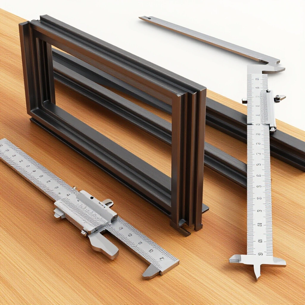
I then turned my attention to the template. By using a digital caliper, I discovered the steel template was slightly bowed. When clamped flat to the workpiece, it “stretched” the layout by nearly 0.020 inches across the diameter. We switched to a thicker, flatter guide and the problem vanished. This taught me that even steel isn’t perfect; its rigidity can be a double-edged sword if the material has internal stresses from the rolling mill.
Troubleshooting Vibrational Chatter from Layout Faults
Machining chatter is a resonant vibration that occurs when a cutting tool bounces against the workpiece, often caused by uneven material removal or improper tool engagement. While often a mechanical issue, chatter can be triggered by layout marks that lead to “interrupted cuts” or varying depths of engagement.
If your layout mark is wavy because the fiber board edge was frayed, your initial cut will be uneven. As the tool hits these high and low spots, it can set up a harmonic vibration. I have seen 2,000 RPM spindle speeds turn into a screaming mess just because the operator was trying to follow a “fuzzy” line. A clean, scribed line on steel provides a much more definite “target” for the tool, allowing for a smoother entry into the cut and reducing the risk of resonant chatter.
Electrical and Magnetic Considerations in Template Use
Electrical interference in fabrication often manifests as arc blow or sensor errors, sometimes caused by the magnetic properties of the tools and materials used during the setup phase. Understanding the magnetic signature of your layout tools is essential when working near sensitive electronics or performing precision welding.
One often overlooked factor is that sheet steel templates can become magnetized. If you are using a magnetic base to hold your guide and then try to TIG weld nearby, you might experience “arc blow,” where the welding arc wanders uncontrollably. Fiber board is naturally non-magnetic and non-conductive, making it a safer choice for layouts on live electrical cabinets or when welding with high-frequency starts.
- Steel: Can hold a magnetic charge, potentially affecting arc stability.
- Fiber board: Di-electric and non-magnetic, ideal for sensitive environments.
- Diagnostic Step: If your arc is wandering, remove all steel templates and magnets from the work area to see if the problem persists.
Systematic Selection Checklist for Layout Guides
Choosing the right material requires a systematic approach to the specific demands of the job. I use a five-point checklist to determine whether I should reach for the fiber board or the sheet steel.
- Environment Check: Is the shop floor subject to high humidity or extreme temperature swings? (Steel for humidity, fiber for temperature stability).
- Usage Frequency: Will this template be used once, or 500 times? (Steel for high repetition).
- Tolerance Requirements: Is the allowable error more or less than 0.010 inches? (Steel for tight tolerances).
- Contamination Sensitivity: Is the workpiece a critical pressure vessel or a non-critical bracket? (Steel for clean welds).
- Handling Needs: Does the template need to be large and easily moved by one person? (Fiber board for weight reduction).
By following these steps, you eliminate the guesswork that leads to “mystery” errors later in the build. Most fabrication failures are not the result of one big mistake, but the result of failing to control these small, early variables.
Actionable Tracking Framework: Layout Quality Log
I recommend keeping a simple log for your most-used templates. This allows you to track “wear-out” before it causes a part failure.
- Date of Creation: When was the guide made?
- Material Type: Steel or Fiber?
- Baseline Measurement: Record a critical dimension (e.g., 24.000″).
- Monthly Re-check: Measure that same dimension. If it has moved more than 0.005″, decommission the template.
- Edge Inspection: Look for nicks or compression under a magnifying glass.
Conclusion
Mastering the art of the layout is about more than just drawing lines; it is about understanding how your tools interact with the physical laws of the shop. Whether you choose the lightweight flexibility of a fiber-based guide or the rugged precision of a steel plate, your success depends on your ability to diagnose and compensate for the inherent weaknesses of each.
If you are seeing consistent errors in your fit-up, stop looking at the end of the process. Go back to the beginning. Check your templates for swelling, wear, and thermal expansion. In the world of high-stakes fabrication, the most important tool you have is not your welder or your mill—it is your ability to systematically eliminate every possible source of error, starting with the very first mark you make on the metal.
FAQ: Troubleshooting Layout and Marking Guides
Why does fiber board cause layout drift over several days?
Fiber board is organic and absorbs moisture from the air. In high humidity, the fibers expand, increasing the overall dimensions of the template. This can cause a layout to “drift” by several thousandths of an inch depending on the weather, leading to inconsistent parts.
Can a steel template cause welding arc blow?
Yes, sheet steel templates can become magnetized through contact with magnetic clamps or ground leads. This magnetic field can deflect the welding arc, a phenomenon known as arc blow, which leads to poor penetration and excessive spatter.
How do I fix a warped steel template without a press?
Small warps in thin gauge steel can often be corrected by “stretching” the short side of the curve. By lightly peening the concave side of the warp with a hammer, you can expand the metal and pull the template back into a flat state.
What is the best way to store fiber-based guides to prevent warping?
Store them flat on a level surface in a dry area. Never lean them against a wall, as the weight of the material combined with moisture will cause them to take a permanent “set” or bow, ruining their accuracy.
Why is scribe pressure more critical for hardboard than steel?
Hardboard is a compressed material. If you apply too much pressure with a sharp scribe, you will compress the fibers and create a groove. Subsequent marks will naturally fall into this groove, even if you are trying to make a slight adjustment, leading to “path memory” errors.
How does the thickness of a steel template affect my layout?
A thicker template (e.g., 10 gauge) provides a more stable wall for the marking tool but increases the “parallax error” if you are not looking straight down at the mark. It also requires a longer scribe tip to reach the workpiece effectively.
Can oils from a template cause welding porosity?
Absolutely. If a steel template is coated in shipping oil or if a fiber board guide has absorbed cutting fluids, these can transfer to the workpiece. When you weld over these residues, they vaporize and create gas pockets (porosity) in the weld bead.
How do I diagnose a “fuzzy” mark on my workpiece?
A fuzzy or wide mark is usually caused by a dull marking tool or a frayed edge on a fiber board template. If the edge of the guide is not crisp, the marking tool will wander, creating a line that is difficult to follow with a saw or drill.
Does temperature affect steel templates more than fiber board?
Yes, steel has a much higher coefficient of thermal expansion. While fiber board is sensitive to moisture, steel will change size noticeably as the shop heats up or cools down, which must be accounted for in high-precision layouts.
Why do my bolt holes not line up when using a fiber board template?
The most common reason is “hole wallow.” If you use the template as a drill guide, the drill bit will quickly wear away the soft fiber board, enlarging the hole in the template and allowing the bit to wander on the actual workpiece.
How do I maintain the edge sharpness on a steel guide?
Periodically stone the edges with a fine-grit whetstone to remove any nicks or burrs caused by dropping the tool or hitting it with other metal parts. A clean, burr-free edge is essential for a precise scribe line.
What is the “memory” effect in sheet metal templates?
Sheet metal that has been cold-rolled often contains internal stresses. When you cut the metal to create a template, those stresses are released, which can cause the template to “spring” or twist out of its intended shape. This must be checked and corrected before use.
(This article was written by one of our staff writers, Paul Whitaker. Visit our Meet the Team page to learn more about the author and their expertise.)