How to Build Scale Structural Mockups with Wood (DIY Guide)
I have spent eighteen years walking the concrete floors of industrial fabrication mills, and if there is one thing I have learned, it is that metal is an unforgiving teacher. When you are staring at a three-ton weldment that doesn’t line up, or a lathe that keeps throwing a 0.005-inch taper over a six-inch cut, the frustration is visceral. You feel it in your gut because every minute of downtime is a drain on your productivity and your pride. We often want to jump straight to the torch or the wrench, but the most effective diagnostic tool in my kit isn’t made of hardened steel. It is a reduced-scale wooden representation of the problem.
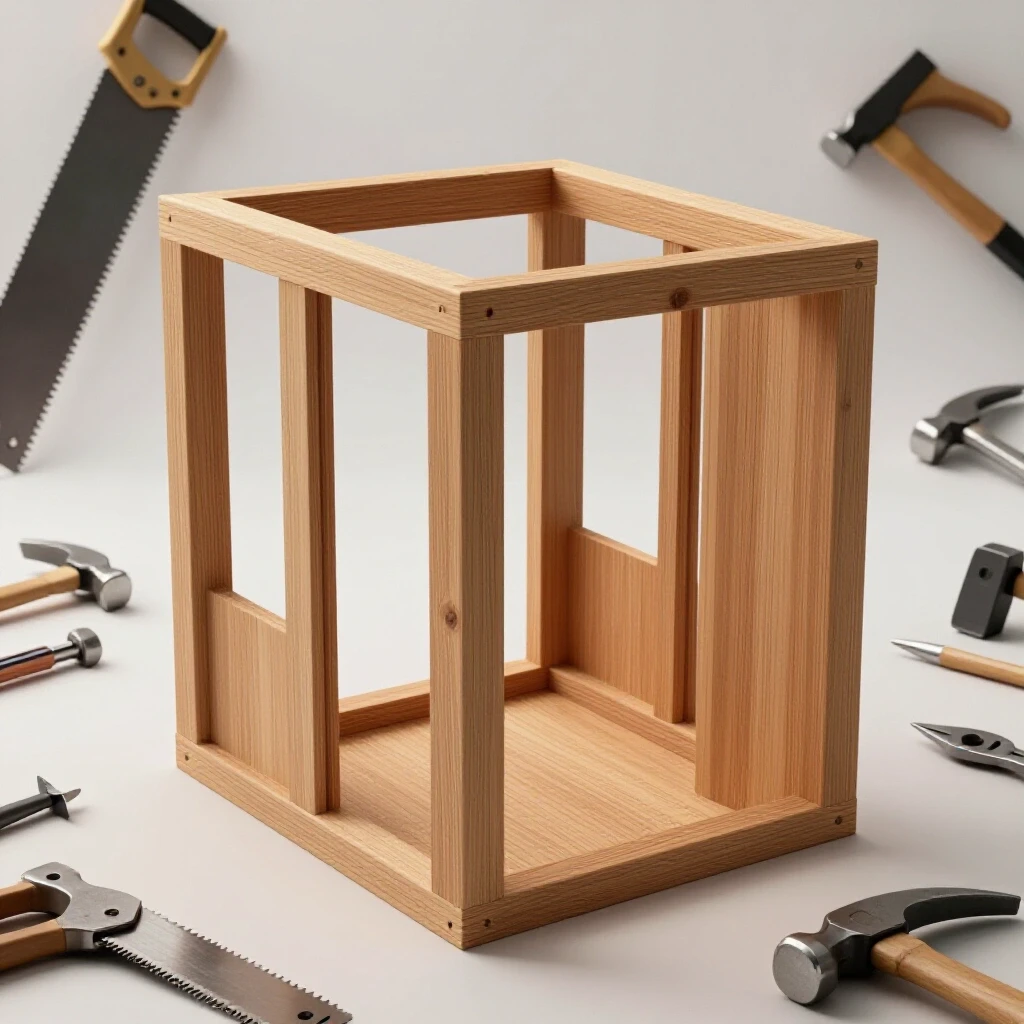
Early in my career, I was tasked with diagnosing a recurring structural alignment fault on a custom-built hydraulic press frame. We had already wasted three days and thousands of dollars in plate steel trying to “fix” it on the fly. The welds were cracking, and we couldn’t figure out if the issue was the sequence of heat or a fundamental geometry error in the base. I went home, grabbed some scrap pine and a table saw, and built a 1:10 scale model of the frame. Within an hour of assembling the wooden pieces, the “ghost” appeared. The way the wood flexed under a simple hand-clamp showed exactly where the stress was concentrating. We weren’t dealing with a welding defect; we were dealing with a leverage problem.
This guide is about using these physical prototypes to master systematic diagnostic methodologies. We are going to look at how building these models allows you to isolate variables, test clearances, and resolve complex machinery issues before you ever strike an arc or engage a spindle.
The Role of Physical Prototypes in Diagnostic Frameworks
A physical prototype serves as a low-stakes environment to test spatial theories and mechanical interactions. It allows a fabricator to visualize complex geometries and identify potential points of interference or structural weakness without the high cost of metal waste or machine wear.
When you encounter an unexpected problem, your first instinct might be to start changing settings on your welder or adjusting the gibs on your mill. However, random guesswork is the enemy of the professional. I use a “Three-Step Isolation” framework: observation, isolation, and variable control. A wooden mockup is the ultimate tool for variable control. By replicating a structural component in wood, you remove the “noise” of metallurgical variables like heat-affected zones or magnetic arc blow. You are left with pure geometry.
Building a scale model allows you to see how parts interact in three dimensions. For example, if you are struggling with a complex lathe alignment checklist, a wooden model of the headstock and bed can help you visualize how a tiny 0.002-inch adjustment at the feet translates to a massive swing at the spindle nose. It’s about building a mental map of the machine’s physics.
Selecting Materials for Geometric Accuracy
The choice of wood for a diagnostic model depends on the specific mechanical issue you are trying to resolve. Stability and straightness are more important than aesthetics because the goal is to create a reliable reference point for troubleshooting metal fabrication fixes.
I generally prefer MDF (Medium Density Fiberboard) or high-quality birch plywood for these models. MDF is particularly useful because it lacks grain direction, meaning it won’t warp as much with humidity changes. This is critical when you are trying to diagnose a structural alignment fault where a fraction of an inch matters. If you use a piece of wet construction lumber, your mockup might develop its own “mechanical errors,” which defeats the purpose of the exercise.
Comparison of Mockup Materials for Diagnostics
| Material | Dimensional Stability | Ease of Modification | Best Use Case |
|---|---|---|---|
| MDF | High | Excellent | Checking clearances and machine paths |
| Birch Plywood | Medium-High | Good | Structural layout and assembly sequencing |
| Pine / Softwood | Low | High | Rough spatial “sanity checks” |
| Hardwood (Oak/Maple) | High | Low | Simulating rigid tool-holding components |
When I’m tracking down tool chatter solutions, I might use a denser hardwood to simulate the rigidity of a tool post. This helps me understand if the vibration is coming from the tool’s overhang or the machine’s base. The goal isn’t to build a toy; it’s to build a diagnostic instrument.
Using Mockups to Isolate Mechanical Alignment Faults
Mechanical alignment involves ensuring that all moving parts of a machine operate on the same plane or axis. When a machine falls out of alignment, it results in tapered cuts, premature bearing failure, or excessive vibration that can ruin a finish.
If you are following a lathe alignment checklist and still getting inconsistent results, a wooden mockup of the assembly can reveal hidden “play” or backlash. Backlash is the clearance or “lost motion” between mating components, such as a lead screw and its nut. In a metal machine, this might be 0.002 inches—hard to see with the naked eye. But if you build a 5:1 scale wooden model of that screw mechanism, that 0.002-inch gap becomes 0.010 inches. Suddenly, the problem is visible.
I once worked on a mill where the spindle was slightly out of square with the table. We kept adjusting the head, but the error persisted. I built a simple wooden “tramming” arm that was three feet long. By swinging this oversized arm, the tiny error at the spindle was magnified at the end of the wood. It showed us that the column itself was leaning, not the head. The mockup didn’t fix the machine, but it told us exactly where the shims needed to go.
Steps for Mapping Diagnostic Paths with Wood
- Identify the primary axis of error (e.g., X-axis drift).
- Determine the scale required to make the error visible (1:1 for small parts, 5:1 for tiny tolerances).
- Construct the “fixed” base of the model from stable MDF.
- Add the “moving” components using simple pins or hinges to simulate machine joints.
- Manually cycle the model to observe where parts bind or diverge.
Troubleshooting Weld Porosity Through Spatial Analysis
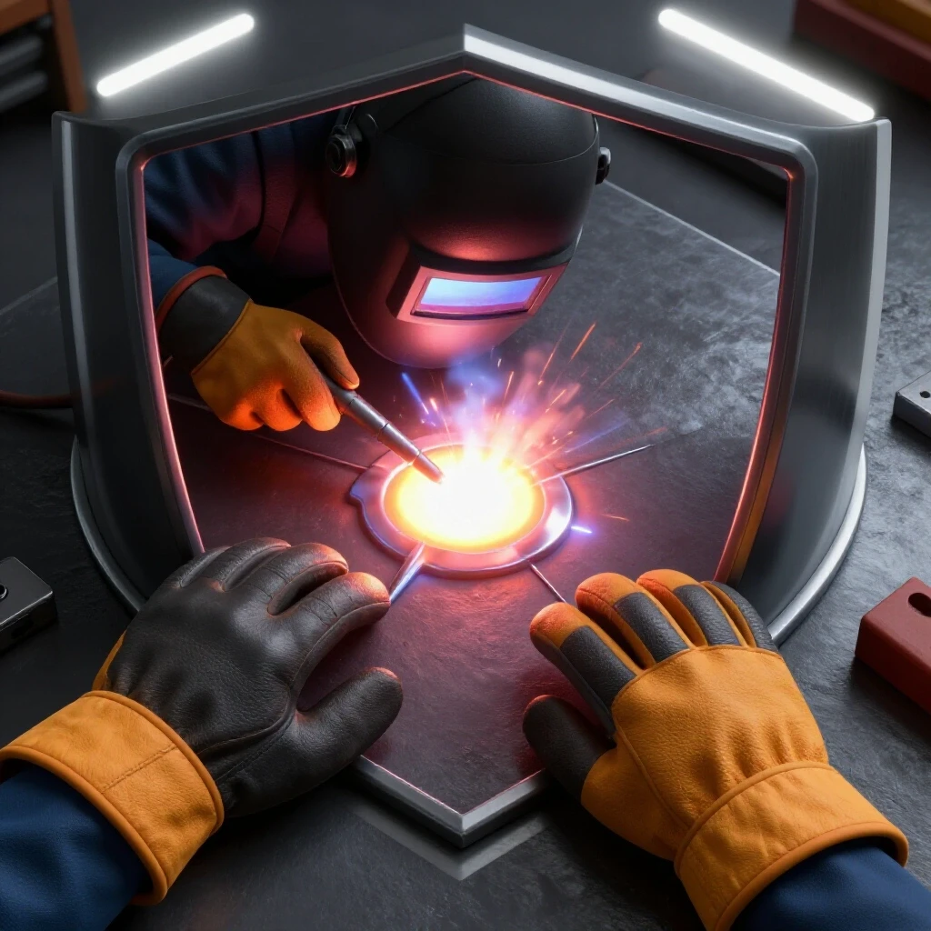
Weld porosity is often caused by atmospheric contamination of the weld pool, but the root cause can be mechanical. If a joint is designed in a way that creates “dead air” pockets or prevents the shielding gas from reaching the root, you will get holes in your weld no matter how high you turn the flow rate.
By building a scale wooden representation of a complex joint, you can physically test the “reach” of your welding torch. I have seen many fabricators struggle with porosity in tight corners. When we built a wooden mockup of the box section, we realized the gas nozzle was hitting a structural rib three inches before the wire could reach the corner. This created a venturi effect, sucking in oxygen and causing porosity.
In this scenario, the wooden model acts as a “fit-test” for the process itself. You can see the torch angle and realize that a 45-degree gas lens won’t fit, but a 90-degree “stubby” kit might. This is a classic example of using metalworking diagnostic guides to solve a problem before a single drop of shielding gas is wasted.
Common Porosity Triggers Found in Mockups
- Restricted Access: The torch cannot maintain a 15-degree lead angle.
- Gas Turbulence: Sharp internal corners in the mockup suggest where gas might swirl and trap air.
- Shielding Gaps: Large openings in the assembly that might allow drafts to blow away the gas.
Dampening Tool Chatter and Vibrational Analysis
Tool chatter is a resonant vibration that occurs when the cutting forces excite the natural frequency of the machine or the workpiece. It leaves a “washboard” finish on the metal and can shatter carbide inserts in seconds.
Diagnosing chatter is difficult because it involves “harmonics”—the way vibrations move through a structure. I use wooden mockups to test different bracing strategies. Wood has different damping characteristics than steel, but the geometry of the vibration remains the same. If a long, thin wooden part vibrates when I tap it, I can add a small wooden brace and see how it changes the sound and movement.
This translates directly to the metal shop. If the wooden mockup shows that a brace at the midpoint kills the vibration, I know that adding a temporary “steady rest” or a heavy clamp to the metal workpiece at that same point will likely solve the chatter.
Metrics for Vibrational Diagnosis
- Frequency (Hz): The pitch of the chatter.
- Amplitude: The depth of the marks on the workpiece.
- Resonant Nodes: Points on the structure that do not move during vibration.
By identifying these nodes on a wooden model, you can place your clamps or supports more effectively. It turns a “trial and error” process into a systematic metal fabrication fix.
Testing Machine Electronics and Path Clearances
Modern CNC machines often suffer from “electrical gremlins” or motor controller faults that cause the machine to stutter or stop. While you can’t build a wooden circuit board, you can use a wooden mockup to test the “physicality” of the code.
Before I run a complex, multi-axis program on a $100,000 piece of equipment, I often build a simplified wooden model of the workpiece. I then run the machine with a “dummy” wooden tool. This allows me to check for “back-EMF” issues—where the motor works too hard and sends a spike of electricity back to the controller—by observing where the machine sounds strained. If the wooden tool hits a part of the mockup, I’ve saved a spindle.
This is especially helpful for identifying “spindle backlash.” If the machine moves to a coordinate but the wooden tool is 0.010 inches off, I know I need to adjust the compensation in the software. It is a safe, quiet way to calibrate a machine that is acting up.
A Case Study in Structural Alignment
I once worked with a shop that was building a large gantry system. Every time they welded the main cross-beam, the whole structure twisted by nearly half an inch. They were convinced the steel was “bad” or the floor was unlevel.
I suggested we stop and build a 1:12 scale model using birch plywood. We replicated the welding sequence using a hot glue gun—which, while not a weld, mimics the “tack and pull” of assembly. As we “glued” the wooden beams together in the same order they had welded the steel, the wooden model twisted in exactly the same way.
The discovery was simple: the sequence of assembly was trapping stress. By changing the sequence on the wooden model, we found a path that kept the structure square. We took that “map” back to the steel, and the next gantry came out within 0.030 inches of perfect. No advanced engineering was needed—just a few hours with some wood and a systematic approach.
Tools and Resources for Diagnostic Modeling
To build effective mockups for troubleshooting, you don’t need a full woodshop, but you do need precision. Here is a list of the tools I keep in my “diagnostic kit”:
- Digital Calipers: For transferring 0.001-inch measurements from the machine to the wood.
- Combination Square: Essential for ensuring the mockup itself is square.
- MDF or Birch Plywood: For dimensional stability.
- Cyanoacrylate (CA) Glue and Activator: For “instant” assembly that mimics tack welding.
- Fine-Tooth Pull Saw: For making clean, accurate cuts without splintering.
- Digital Protractor: To measure angles on the machine and replicate them in the model.
- Feeler Gauges: To measure gaps in the mockup that correspond to “play” in the machine.
Actionable Benchmarks for Fabrication Fixes
When you are using a mockup to diagnose a problem, you need to know what “good” looks like. Here are some benchmarks I use:
- Mechanical Tolerances: For most diagnostic models, a tolerance of +/- 0.010 inches is sufficient to identify major geometric faults.
- Voltage Drop Limits: If testing electrical paths, any drop over 3% usually indicates a bad connection or an undersized wire.
- Backlash Limits: On a manual machine, backlash over 0.005 inches in a lead screw usually requires adjustment or replacement of the nut.
- Weld Inspection: Porosity should be zero. If a mockup shows a torch angle of less than 45 degrees is required, expect gas coverage issues.
Conclusion: The Path to Permanent Repairs
Troubleshooting is not about being a “wizard” who can hear a bad bearing from across the room. It is about being a detective who refuses to move to the next step until the current one is verified. Building reduced-scale wooden representations is a way to slow down and “interrogate” the problem.
Whether you are dealing with tool chatter that ruins your finish, or a structural twist that makes assembly a nightmare, the solution is usually hidden in the geometry. By stepping away from the heavy steel and the high-voltage cabinets for an hour to build a model, you gain a perspective that no sensor or software can provide. You see the “why” behind the “what.”
The next time a machine throws a code or a weld looks like Swiss cheese, don’t reach for the hammer. Reach for a piece of wood. Build the problem, and the solution will usually build itself.
FAQ: Using Wood Mockups for Metalworking Diagnostics
How can a wood mockup help me find the source of tool chatter?
Tool chatter is often caused by a lack of rigidity in the setup. By building a scale model of your workpiece and tool holder, you can manually apply pressure and see where the structure deflects. Wood’s flexibility actually makes these “soft spots” easier to see. If the mockup bends at a specific joint, that is where you need to add mass or bracing on your metal machine.
Is wood stable enough to diagnose a 0.002-inch alignment error?
While wood itself moves with humidity, a model made of MDF or plywood is stable enough for “comparative diagnostics.” You aren’t using the wood to set the final measurement; you are using it to see the direction and nature of the error. A 0.002-inch error on a lathe can be magnified by using a longer “arm” on your wooden model, making it visible to the eye.
Can I use glue to simulate welding in a structural mockup?
Yes, using a fast-setting CA glue is an excellent way to simulate the assembly sequence. While glue doesn’t shrink exactly like a cooling weld bead, the order in which you “lock” the parts together will reveal if your assembly sequence is introducing internal stress or “pulling” the structure out of square.
Why not just use 3D CAD software instead of a wooden model?
CAD is powerful, but it often lacks the “feel” of physical interaction. A wooden mockup allows you to physically reach in with a tool or a hand to check for clearances. It also reveals “real-world” issues like gravity-induced sag or the difficulty of reaching a bolt, which are sometimes missed in a perfect digital environment.
What is the best scale for a diagnostic mockup?
For large structural issues, 1:10 or 1:12 is standard. For small mechanical parts like a gear box or a tool post, 1:1 or even 2:1 (oversized) is better. The goal is to make the parts large enough to handle and the errors large enough to see.
How do I account for the thickness of the wood versus the thickness of the metal?
This is a critical step. If you are using 1/2-inch plywood to represent 1/2-inch steel plate, your scale is 1:1. If you are building a 1:10 scale model, you should ideally use material that is 1/10th the thickness. However, for most geometric troubleshooting, simply keeping the centerlines of the parts accurate is more important than the material thickness.
Can a mockup help with electrical troubleshooting?
It helps with the “physical” side of electronics. You can use a mockup to plan wire routing to avoid “noise” or interference from motors. It also helps you see if a moving part of the machine will eventually pinch or rub through a wire harness, which is a common cause of intermittent “electrical gremlins.”
How much time should I spend on a mockup?
A diagnostic mockup should be “quick and dirty.” Don’t sand it, don’t paint it, and don’t worry about beauty. If it takes you more than two hours to build, you are likely over-complicating it. The goal is to get an answer to a specific question, like “Why won’t this bolt line up?” or “Where is the vibration coming from?”
(This article was written by one of our staff writers, Paul Whitaker. Visit our Meet the Team page to learn more about the author and their expertise.)