How to Safely Wire a 100A Subpanel in Garage Shops (Guide)
I have spent the better part of two decades under the flickering hum of shop lights, chasing ghosts in machine tools. There is a specific kind of frustration that sets in when a TIG arc begins to wander for no apparent reason, or when a precision lathe starts producing a finish that looks more like a topographical map than a smooth cylinder. Early in my career, I spent three days tearing down a bridge mill because of intermittent spindle stalls, only to realize the machine wasn’t the problem. The issue was the power supply.
Most fabricators approach their shop setup as a series of mechanical challenges, but the electrical backbone is what dictates the success of every weld and every cut. When your compressor kicks on and your welder’s cooling fan slows down, you aren’t just dealing with a minor annoyance; you are looking at a voltage drop that can lead to shielding gas inconsistencies and thermal instability in your welds. Establishing a dedicated 100-amp power distribution point in your workspace is often the first step in a systematic diagnostic approach to eliminating these variables.
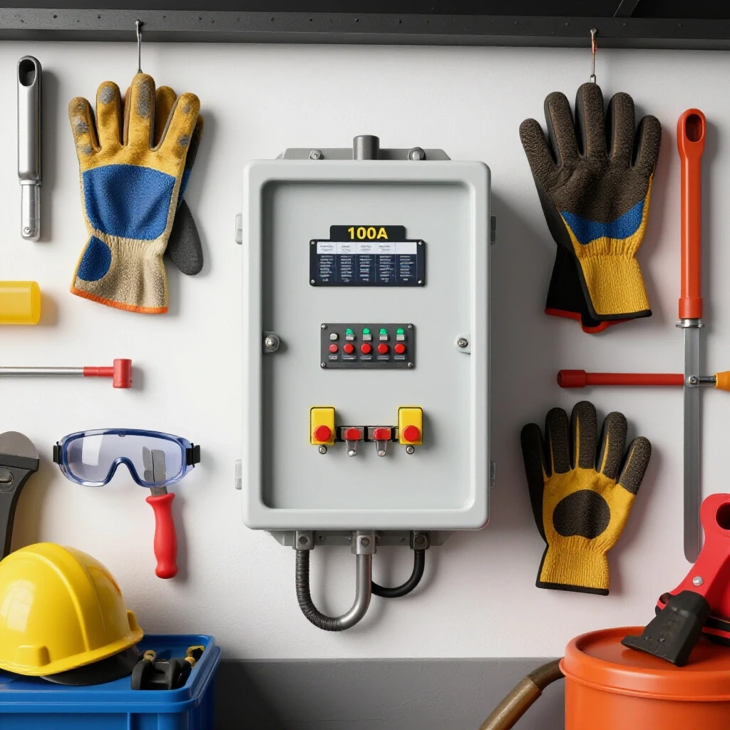
In this guide, I will break down the process of installing a high-capacity feeder system designed to handle the heavy inductive loads of a modern fabrication shop. We will look at how to size conductors, manage grounding for sensitive electronics, and ensure your machinery has the stable voltage it needs to perform within factory tolerances.
Establishing the Load Profile for a Multi-Tool Fabrication Environment
A load profile is a calculated estimate of the maximum electrical demand a shop will face when multiple machines are running simultaneously. By identifying the peak amperage of your largest motor and adding it to the continuous requirements of lighting and auxiliary tools, you can determine if a 100-amp capacity meets your diagnostic and operational needs.
Before you ever strip a wire, you have to understand the math of your shop. I’ve seen guys install a subpanel only to find that their plasma table and 5hp compressor together trip the main breaker every time the air tank refills. We use the National Electrical Code (NEC) as our baseline, specifically Article 220, to calculate these loads. For a fabrication shop, you generally take the full-load amperage (FLA) of your largest motor, multiply it by 125%, and then add the FLA of all other equipment that might run at the same time.
If you are running a 50-amp welder, a 20-amp compressor, and 10 amps of lighting and fans, your “concurrent load” is significant. A 100-amp service provides the headroom necessary to prevent voltage sag. In my experience, keeping your total active load under 80% of the panel’s rating (80 amps for a 100-amp panel) is the “sweet spot” for maintaining tool RPM and arc consistency.
Fabrication Shop Load Calculation Example
| Equipment Type | Rated Amperage (FLA) | Calculation Factor | Total Assigned Amps |
|---|---|---|---|
| Largest Motor (e.g., 5HP Compressor) | 22A | 1.25x | 27.5A |
| Multi-Process Welder | 50A | 1.0x | 50A |
| Shop Lighting (LED) | 4A | 1.0x | 4A |
| Dust Collection / Ventilation | 12A | 1.0x | 12A |
| Total Calculated Demand | — | — | 93.5A |
In the scenario above, a 100-amp feeder is just barely sufficient. If you plan to add a CNC plasma table later, you would be pushing the limits, which is where we start seeing “electrical gremlins” like controller resets or erratic sensor readings.
Selecting Conductors to Mitigate Voltage Drop
Conductor selection involves choosing the correct wire gauge and material (copper or aluminum) to carry current without excessive heat buildup or voltage loss. Proper sizing ensures that your 230V machinery actually receives 230V, rather than 210V, which can cause motors to overheat and lose torque.
When I’m troubleshooting tool chatter on a mill, one of the first things I check is the voltage at the motor terminals while the machine is under load. If the feeder wires are too small for the distance they travel, the voltage drops. This drop forces the motor to draw more current to do the same amount of work, leading to heat and vibration. For a 100-amp subpanel, you are typically looking at #3 AWG Copper or #1 AWG Aluminum for the “hots” and neutral, assuming the run is under 50 feet.
If your garage is 100 feet or more from the main service entrance, you must upsize the wire to account for resistance. I’ve seen 100-amp panels wired with #4 copper over long distances that caused TIG welders to struggle with arc starts. Use the following table as a diagnostic baseline for wire sizing based on distance.
Feeder Wire Sizing for 100A Capacity (75°C Terminations)
| Distance to Panel | Copper Wire Size (AWG) | Aluminum Wire Size (AWG) | Expected Voltage Drop (at 80A) |
|---|---|---|---|
| 0 – 50 Feet | #3 | #1 | < 2% |
| 50 – 100 Feet | #2 | #1/0 | < 2.5% |
| 100 – 150 Feet | #1 | #3/0 | < 3% |
| 150+ Feet | #1/0 | #4/0 | Consult Engineer |
- Note: Always use THHN/THWN-2 wire if pulling through conduit.
- Note: Aluminum is cost-effective but requires larger conduit and anti-oxidant paste (Noalox) on all connections.
The Critical Role of Grounding and Bonding in Fabrication
Grounding refers to the safety path that directs fault current back to the source, while bonding is the joining of all metallic components to ensure they stay at the same electrical potential. In a shop environment, proper grounding is the only thing preventing your steel welding table from becoming “live” if a machine’s insulation fails.
One of the most common errors I find in garage subpanels is the failure to separate the neutral and ground bars. In your main house panel, the neutral (white) and ground (green/bare) are bonded together. However, in a subpanel, they must remain isolated. If you bond them in the shop, you create parallel paths for return current. This can induce “stray voltage” into the chassis of your machines.
For fabricators using High-Frequency (HF) start TIG welders, poor grounding is a nightmare. HF interference can jump to ungrounded metal objects, causing digital readouts (DROs) on lathes to flicker or CNC controllers to crash. You must ensure the subpanel has a dedicated ground wire (usually a #8 or #6 copper) running back to the main panel’s ground bus.
- Isolation Step: Ensure the green “bonding screw” that comes with the subpanel is removed or not installed.
- Verification: Use a multimeter to check continuity between the neutral bar and the panel enclosure. There should be NO continuity.
- Safety Check: Every machine with a metal frame must be bonded to the shop’s grounding system to prevent “tingle” shocks when touching two different tools.
Physical Installation and Conduit Management
Conduit management is the systematic routing of electrical piping to protect conductors from physical damage, such as sparks, grinding dust, or accidental impacts. In a metal shop, using Electrical Metallic Tubing (EMT) is standard because it provides a degree of shielding against electromagnetic interference (EMI).
I prefer using 1.25-inch or 1.5-inch EMT for a 100-amp feeder. While 1-inch conduit might technically fit the wires, it makes the “pull” incredibly difficult and increases the risk of nicking the insulation. When I’m diagnosing an intermittent short circuit, it often traces back to a wire that was pulled too hard around a sharp bend, compromising the jacket.
- Mounting the Enclosure: Position the panel at eye level in a dry location. Ensure there is 36 inches of clear workspace in front of it.
- Bending Conduit: Use a dedicated conduit bender to create smooth 90-degree sweeps. Avoid more than 360 degrees of total bends between pull points.
- Pulling Wire: Use a nylon fish tape and wire pulling lubricant. This isn’t just to make it easier; it prevents friction-induced heat from damaging the wire’s outer skin.
- Terminations: This is where many shops fail. Use a torque wrench. Most 100-amp lugs require between 45 and 50 lb-in of torque. Under-torqued connections create resistance, which leads to heat, which leads to voltage drops.
Diagnostic Testing: Verifying Power Stability
Diagnostic testing is the final phase where we use precision instruments to confirm that the electrical system is operating within safe and functional parameters. We are looking for stable voltage, low resistance, and proper phase-to-phase balance.
Once the panel is hot, but before you plug in your $5,000 welder, you need to run a series of tests. I use a True RMS multimeter for this. Cheap meters often struggle with the “dirty” power found in industrial settings and can give false readings.
- Voltage Test (No Load): Measure between the two hot lugs. You should see approximately 240V. Measure each hot to neutral; you should see 120V.
- Voltage Test (Under Load): Have someone strike an arc with a welder or start the compressor while you monitor the voltage at the subpanel. A drop of more than 3-4% (about 7-9 volts) suggests a high-resistance connection or undersized feeder wires.
- Thermal Inspection: After the shop has been running for an hour, use an infrared thermometer to check the temperature of the main lugs and breakers. Any connection significantly hotter than the surrounding wires (usually above 140°F or 60°C) is a sign of a loose termination.
Troubleshooting Common Power-Related Fabrication Issues
When a machine isn’t performing correctly, we often blame the tool itself. However, the subpanel is the first place I look when I see specific symptoms in the shop.
Identifying the Root Cause of Tool Chatter and Stalling
Tool chatter is often a mechanical resonance issue, but it can be exacerbated by inconsistent motor speed. If your lathe motor is hunting for RPM because the voltage is fluctuating, you will never get a clean finish. This is especially true for machines with Variable Frequency Drives (VFDs). VFDs are sensitive to “line noise” and voltage spikes.
If you experience chatter, check the following: 1. Phase Balance: On 240V circuits, ensure both “legs” are providing equal voltage. A difference of more than 2-3 volts can cause motor vibration. 2. Harmonic Distortion: If you have many LED lights or cheap switching power supplies on the same circuit as your mill, they can “pollute” the sine wave, causing the motor to run rough.
Solving Welding Porosity Through Electrical Consistency
Welding porosity is usually a gas coverage issue, but “electrical porosity” is a real phenomenon. If your wire feeder’s motor is fluctuating because of a shared circuit with a cycling compressor, your wire feed speed (WFS) will be inconsistent. This causes the arc length to change rapidly, which can trap atmospheric gases in the weld pool.
By moving your welder to a dedicated circuit on a 100-amp subpanel, you isolate it from the “noise” of other tools. I once solved a chronic porosity issue on a robotic weld cell simply by re-torquing the ground lugs in the subpanel. The loose ground was causing the arc to “flutter,” which looked exactly like a gas shield failure.
Advanced Maintenance: The 6-Month Shop Audit
A shop audit is a recurring inspection of your electrical and mechanical systems to catch minor wear before it leads to catastrophic failure. In a metalworking environment, vibration and metal dust are your primary enemies.
Metal dust is conductive. Over time, it settles inside your subpanel and on your breaker contacts. Every six months, I perform the following “Clear and Tighten” routine: 1. Power Down: Turn off the main feeder breaker. 2. Vacuum: Use a non-conductive vacuum attachment to remove dust. Never use compressed air, as it drives the dust deeper into the breaker mechanisms. 3. Torque Check: Heat cycles (expansion and contraction) can loosen lugs over time. Re-verify torque settings on the main feeder lugs. 4. Visual Check: Look for “bluing” or discoloration on the copper bus bars, which indicates localized overheating.
Essential Tools for Electrical Diagnostics in the Shop
To maintain a professional-grade power system, you need more than just a pair of pliers. These are the tools I keep in my diagnostic kit for shop power issues.
- True RMS Multimeter: Essential for measuring voltage on circuits with VFDs or welders.
- Clamp-on Ammeter: Allows you to measure the current draw of a machine while it’s running without breaking the circuit.
- Infrared (IR) Thermometer: For identifying hot spots in the panel or on motor housings.
- Circuit Analyzer: A plug-in device that checks for correct wiring, ground impedance, and GFCI functionality on 120V outlets.
- Torque Screwdriver/Wrench: To ensure all breaker and lug connections meet manufacturer specifications (usually measured in inch-pounds).
Summary of Technical Benchmarks for Shop Power
| Metric | Ideal Value | Warning Threshold |
|---|---|---|
| Main Lug Torque | 45 – 50 lb-in | < 40 lb-in (Loose) |
| Voltage Drop (Full Load) | < 3% | > 5% (Undersized Wire) |
| Neutral-to-Ground Resistance | 0 Ohms (at Main) | > 2 Ohms (at Subpanel) |
| Operating Temperature | < 120°F | > 150°F (Overload/Resistance) |
| Phase-to-Phase Balance | < 1% Variance | > 3% Variance |
Mastering the electrical foundation of your shop is no different than mastering the tram of a mill or the flow of a weld puddle. It requires a systematic approach, a respect for tolerances, and a refusal to accept “good enough.” When your power is stable, your machines run smoother, your welds are cleaner, and your diagnostic time is cut in half because you’ve eliminated the most common variable of all: the electricity itself.
Frequently Asked Questions
Why can’t I just use a 60-amp subpanel for my garage?
While a 60-amp panel can run a single welder or a small compressor, it lacks the “surge capacity” required for a professional fabrication environment. Modern inverter welders and large 5HP compressors have high inrush currents. A 100-amp panel provides the necessary headroom to prevent voltage sag, which protects your machine’s sensitive electronics and ensures consistent motor torque during heavy cuts.
Do I need a separate ground rod for my garage subpanel?
According to the NEC, if the garage is a detached building, you generally need to install a ground rod system (usually two rods spaced 6 feet apart) and bond it to the subpanel’s ground bus. However, you must still run a four-wire feeder (two hots, one neutral, one ground) from the main house panel. The ground rod provides a path for lightning and external surges, while the fourth wire provides the safety path for internal faults.
Can I use aluminum wire for the 100-amp feeder?
Yes, aluminum (specifically AA-8000 series) is commonly used for feeders. It is significantly lighter and cheaper than copper. However, you must use a larger gauge (typically #1 or #1/0 for 100A) and you must apply a listed anti-oxidant joint compound to the stripped ends to prevent oxidation, which can lead to high-resistance connections and fires.
What causes my TIG welder to trip the breaker even when I’m not at max power?
This is often caused by “nuisance tripping” due to harmonic distortion or the high-frequency start of the welder. If your breaker is a GFCI or AFCI type, the HF start can confuse the internal circuitry. For dedicated welder circuits, a standard thermal-magnetic breaker is usually required, provided it is sized correctly for the welder’s “Duty Cycle” as per NEC Article 630.
How do I know if my voltage drop is affecting my weld quality?
If you notice your arc becoming “stiff” or “unstable” when your shop’s heater or compressor kicks on, you likely have a voltage drop issue. You can verify this by measuring the voltage at the welder’s input while striking an arc. A drop of more than 10 volts during the start of the weld is a clear indicator that your feeder wires are either too small or have a high-resistance connection.
Is it necessary to use conduit inside the garage?
While some local codes allow for Romex (NM-B) inside finished walls, in a fabrication shop, exposed wiring is a major hazard. Grinding sparks, hot slag, and sharp metal stock can easily slice through plastic-jacketed wire. Running your circuits in EMT (Electrical Metallic Tubing) provides physical protection and serves as an additional layer of EMI shielding for CNC equipment.
What is the “floating neutral” and why is it important?
A floating neutral refers to the neutral bus bar in a subpanel being electrically isolated from the ground bus and the metal enclosure. In a subpanel, the neutral should only be connected to the main panel’s neutral. If they are bonded in the subpanel, return current will flow through the ground wires and the metal conduit, which can cause interference with sensitive tools and create a shock hazard on machine chassis.
How often should I check the connections in my subpanel?
In a shop with high-vibration machinery (like power hammers or large compressors), I recommend a visual inspection and a torque check every 6 to 12 months. Thermal expansion from heavy welding sessions can gradually loosen mechanical lugs. A loose lug is the leading cause of “burnt out” breakers and intermittent power loss in fabrication shops.
Why does my lathe’s digital readout (DRO) reset when I start my welder?
This is usually a sign of “Electrical Noise” or poor grounding. The high-frequency start or the heavy current draw of the welder creates an electromagnetic field. If your DRO cables aren’t shielded or if your subpanel grounding is weak, this noise travels through the ground system and disrupts the low-voltage signals in your DRO. Ensuring a solid, low-resistance ground path in your 100-amp panel is the primary fix.
Can I run a 100-amp subpanel from a 100-amp main house service?
Technically, you can, but you must perform a load calculation of the entire property first. If your house uses electric heating, an electric range, and a clothes dryer, you may not have enough “spare” capacity to feed a 100-amp shop panel. In many cases, you may need to upgrade your main service to 200 amps to safely support a fully equipped fabrication shop.
(This article was written by one of our staff writers, Paul Whitaker. Visit our Meet the Team page to learn more about the author and their expertise.)