How to Replace an Angle Grinder On Off Switch (DIY Guide)
There is a specific kind of silence that falls over a shop when a primary tool fails. One minute, you are grinding down a root pass or prepping a bevel, and the next, the motor cuts out entirely. For those of us who have spent decades in fabrication, these interruptions are more than just a nuisance; they are a breakdown in the workflow that can lead to missed deadlines and mounting frustration.
In my fifteen years as a diagnostic specialist, I have learned that tools rarely fail without a reason. Whether I am tracking down the source of welding porosity in a high-pressure pipe or isolating the cause of tool chatter on a large lathe, I rely on a systematic approach. When a corded angle grinder refuses to fire up, the problem often lies within the manual toggle or trigger mechanism. Instead of guessing, we use a process of elimination to restore the tool to factory specifications.
Systematic Diagnostics for Power Tool Failures
Systematic diagnostics is the practice of isolating individual variables within a machine to find the root cause of a failure. It involves moving from the most accessible components to the most complex, ensuring that no simple fix is overlooked before a full teardown.
When a piece of equipment stops responding, I always start at the power source. In a busy shop, it is easy to overlook a tripped breaker or a loose extension cord. If the outlet is live, I move to the tool’s power lead. Over time, the copper strands inside a cord can fatigue from constant bending, usually near the strain relief. I use a multimeter to check for continuity, which is a continuous path for electrical current. If the cord shows a resistance of less than 1.0 Ohm from the plug to the internal terminals, the cord is functional, and the issue lies deeper.
| Component | Symptom of Failure | Diagnostic Reading |
|---|---|---|
| Power Cord | Intermittent power when moved | Infinite Ohms (Open Circuit) |
| Carbon Brushes | Motor sparking or low RPM | Visual wear below 1/4 inch |
| Internal Switch | No response to trigger pull | No continuity when engaged |
| Motor Armature | Burning smell or heavy vibration | Visible scorch marks |
Accessing the Internal Control Mechanism
Accessing the internal control mechanism requires the careful removal of the tool’s outer casing to expose the electrical connections. This stage is critical because it allows for a visual inspection of the wiring and the mechanical linkage that activates the motor.
I begin by ensuring the tool is unplugged. This is a non-negotiable safety step. I then use a precision screwdriver to remove the housing screws. In many professional-grade grinders, these are Torx or Phillips head fasteners. I keep these in a magnetic tray because losing a specialized screw can stall the repair. Once the rear cover is removed, I can see the trigger assembly and the wires leading to the motor. I look for signs of heat damage, such as melted plastic or discolored wire insulation, which often point toward a high-resistance failure in the contact points.
Electrical Continuity and Switch Resistance
Electrical continuity is the presence of a complete path for current flow, while resistance, measured in Ohms, is the opposition to that flow. In a healthy power tool, the control unit should have near-zero resistance when closed and infinite resistance when open.
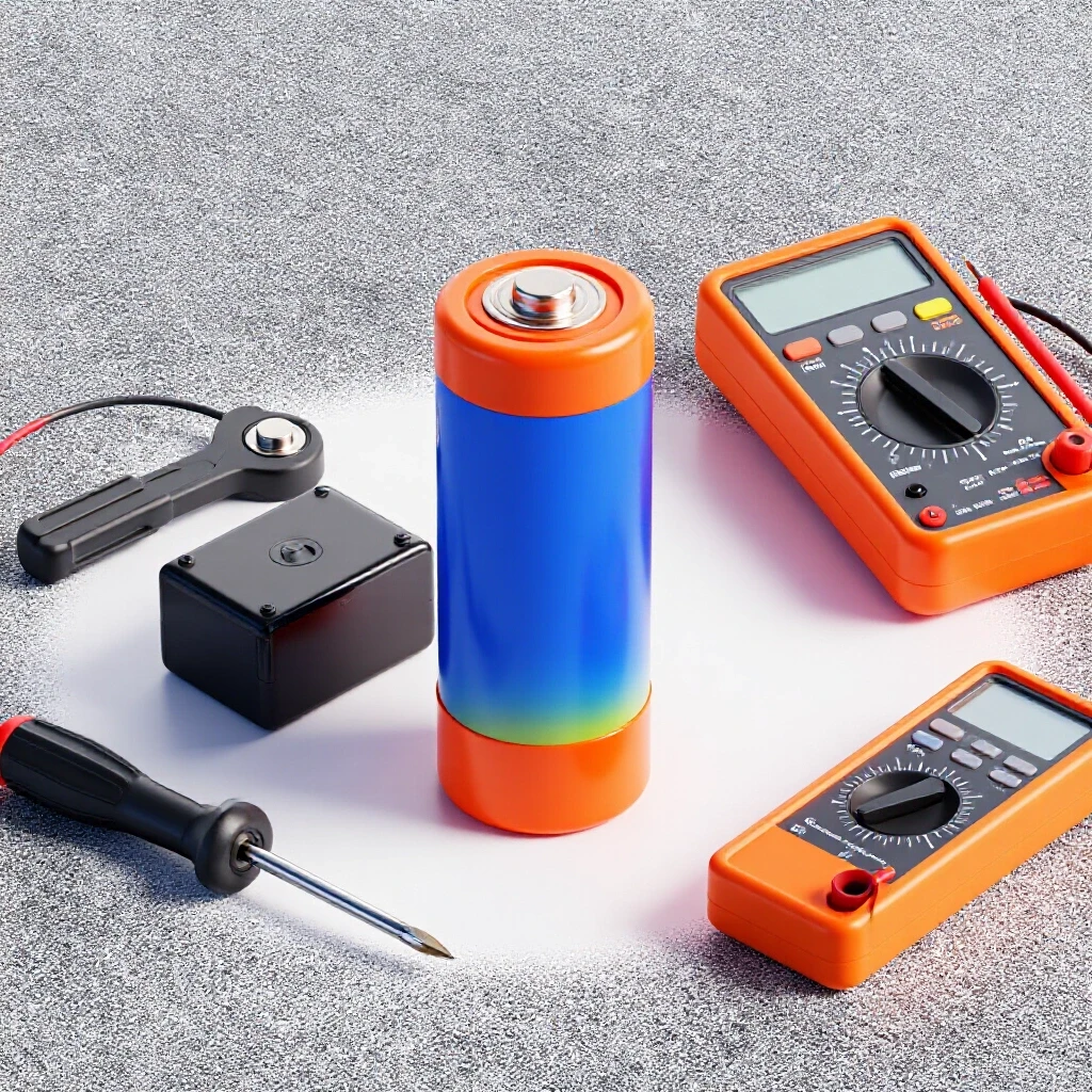
Using a digital multimeter, I set the dial to the continuity or lowest Ohms setting. I place the probes on the input and output terminals of the internal toggle. When I flip the toggle to the “on” position, the meter should beep or show a reading close to 0.2 to 0.5 Ohms. If the meter shows “OL” (Open Loop) or a high resistance value like 50 Ohms, the internal contacts are likely pitted or fouled with metallic dust. This dust is a common byproduct in fabrication shops and can easily migrate into the housing, causing the mechanism to fail prematurely.
- Check the input terminals for 120V (if testing live, which requires extreme caution).
- Test the output side of the trigger to ensure voltage passes through.
- Inspect the mechanical linkage for physical obstructions or grit.
- Verify that the return spring is strong enough to snap the tool to the “off” position.
Removing the Faulty Component
Removing the faulty component involves disconnecting the lead wires and unseating the physical housing of the trigger or toggle from the tool’s frame. This must be done without straining the delicate copper wires that lead to the motor field.
In my experience, the most common mistake is pulling on the wires themselves rather than the connectors. Most grinders use spade terminals or screw-down clamps. If it is a spade terminal, I use needle-nose pliers to grip the metal connector and pull it straight off. If the wires are held by screws, I back them out just enough to release the wire. I always take a photo of the wiring configuration before disconnecting anything. Even for an experienced fabricator, it is easy to swap a hot and neutral lead when you are focused on getting back to work.
Preparing for the Replacement Installation
Preparing for the replacement installation means cleaning the interior of the tool and verifying that the new part matches the factory specifications of the original. This ensures that the repair is permanent and does not introduce new variables like vibration or heat.
I use compressed air to blow out any accumulated grinding dust from the motor housing. Metal dust is conductive; if it builds up around the new electrical contacts, it can cause a short circuit. I then compare the new part to the old one. I check the amperage rating, which is typically 10 to 15 Amps for a standard 4.5-inch grinder. Using a part with a lower rating will lead to rapid failure under the heavy loads common in structural steel work.
Re-wiring the Control Mechanism
Re-wiring the control mechanism is the process of attaching the power leads to the new component and ensuring the connections are mechanically and electrically sound. A loose connection here will create heat, which can melt the housing or cause the tool to cut out under load.
I strip about 1/4 inch of insulation from the wires if the ends look frayed. I prefer to see clean, bright copper. If the tool uses screw terminals, I wrap the wire clockwise around the screw so that tightening the screw pulls the wire tighter. I torque these screws until they are snug, but I avoid over-tightening, which can strip the plastic threads of the switch body. For spade connectors, I ensure the fit is tight. If the connector slides on too easily, I use pliers to gently crimp the female end for a more secure grip.
- Ensure no stray wire strands are sticking out from the terminals.
- Double-check the wiring against the photo taken during disassembly.
- Verify that the “hot” wire (usually black) and the “neutral” wire (usually white) are in their correct positions.
- Confirm that the ground wire (green) is securely fastened to the tool’s metal frame if applicable.
Proper Cable Routing and Housing Reassembly
Proper cable routing involves tucking the internal wires into their designated channels so they are not pinched when the housing is closed. Pinched wires are a major cause of post-repair failures and can lead to electrical shocks if the insulation is breached.
I carefully lay the wires back into the grooves molded into the plastic handle. I pay close attention to the area around the screw holes. If a wire crosses a screw path, the fastener will drive right through it. Once the wires are settled, I place the top half of the housing back on. It should seat flush with almost no pressure. If there is a gap of more than 0.010 inches, something is misaligned inside. I never force the housing shut with the screws; I find the obstruction and move it first.
Verification and Post-Repair Testing
Verification and post-repair testing is the final phase where the tool is checked for safety and functionality before being returned to the shop floor. This involves both mechanical and electrical checks to ensure the repair was successful.
Before plugging the tool in, I manually toggle the trigger several times. It should move freely and click into place without sticking. I then perform a final continuity test from the plug to the tool while the switch is on. Once satisfied, I plug the tool into a GFCI-protected outlet. I start the grinder at a low-load state, listening for any unusual sounds. I look for excessive sparking at the brushes, which could indicate a timing issue or a poor connection. If the tool runs smoothly for thirty seconds, it is ready to go back to the fabrication table.
Case Study: The Intermittent Grinder Failure
I once worked with a fabricator who was struggling with a grinder that would cut out every time he applied pressure to a weld. He assumed the motor was burning out due to the heavy-duty nature of the work. We brought it to the bench and performed a systematic teardown.
Upon inspection, we found that the internal toggle hadn’t actually failed electrically. Instead, a large shard of metal from a previous grinding operation had wedged itself into the trigger linkage. This prevented the switch from fully engaging the internal contacts. Under the vibration of heavy grinding, the contact would bounce, causing the motor to stall. We cleaned the linkage, applied a small amount of non-conductive grease, and the tool performed perfectly. This saved the shop the cost of a new machine and taught the team the value of a thorough visual inspection.
Troubleshooting Framework for Electrical Tool Issues
- Isolate the Power Source: Test the outlet with a known working device.
- Inspect the Exterior: Look for cuts in the cord or damage to the plug.
- Check the Brushes: Ensure the carbon brushes are long enough to contact the commutator.
- Test the Switch Continuity: Use a multimeter to verify the internal contact’s health.
- Examine the Wiring: Look for loose terminals or heat-damaged insulation.
- Clean the Internals: Remove metallic dust that can cause tracking or shorts.
- Verify Part Compatibility: Ensure the replacement part matches the original’s voltage and amperage.
- Functional Test: Run the tool under no-load and then light-load conditions.
Frequently Asked Questions
Why does my grinder work only when I wiggle the cord near the handle? This usually indicates a break in the copper strands inside the power cord, typically right where it enters the tool. The constant flexing at the strain relief causes the metal to fatigue. Replacing the cord or shortening it past the break is the standard fix.
Can I use a switch from a different model if it looks the same? It is not recommended. Even if the exterior looks identical, the internal amperage rating or the way the mechanical linkage interacts with the trigger may differ. Always use factory-spec parts to ensure the tool handles the electrical load safely.
What causes the internal contacts to burn out in the first place? In a fabrication environment, fine metallic dust is the primary enemy. It enters the housing and creates a high-resistance path or causes arcing between the contacts. Overloading the tool by pressing too hard also draws more current, which generates heat and degrades the switch.
How do I know if the problem is the switch or the motor brushes? If the tool is completely dead, it is often the switch or the cord. If the tool runs but sparks heavily, loses power, or smells like burning, it is likely the brushes or the motor armature. A continuity test on the switch will quickly confirm if it is the culprit.
Is it safe to bypass the switch to see if the motor works? While this can be done for a quick diagnostic test, it is extremely dangerous. An angle grinder that starts the moment it is plugged in can jump off the bench and cause serious injury. It is much safer to use a multimeter to test for continuity without power.
What tools do I need for this repair? A basic kit should include a set of Torx and Phillips screwdrivers, needle-nose pliers, a wire stripper, and a digital multimeter. A magnetic tray for screws and a can of compressed air are also highly beneficial.
How tight should the internal wiring screws be? They should be snug enough that the wire cannot be pulled out by hand, but not so tight that you deform the wire or strip the plastic housing. A torque of about 10 to 15 inch-pounds is usually sufficient for these small terminals.
What should I do if the new switch doesn’t fix the problem? If the switch and cord both test positive for continuity, the issue is likely in the motor field or the armature. Check the brushes again to ensure they are seated correctly and making firm contact with the commutator.
Does it matter which wire goes to which terminal on the switch? Yes. While the motor might spin either way, most switches are designed to break the “hot” (black) wire for safety. Reversing them can leave the tool’s internal components energized even when the switch is off, creating a safety hazard.
How often should I clean the inside of my grinders? In a high-production shop, blowing out the tools with compressed air once a week can significantly extend the life of the internal electronics. This prevents the buildup of conductive dust that leads to component failure.
(This article was written by one of our staff writers, Paul Whitaker. Visit our Meet the Team page to learn more about the author and their expertise.)