How to Identify and Prevent Aluminum TIG Defects (Tutorial)
I have spent the last 18 years in fabrication shops, often standing over a machine that worked perfectly yesterday but is producing garbage today. Aluminum TIG welding is perhaps the most sensitive process we handle. It is a dance of chemistry, physics, and electrical precision. When a weld suddenly shows pepper-like inclusions or the arc begins to wander like a lost traveler, the natural instinct is to start turning every knob on the inverter. I have learned the hard way that “knob-turning” is not a strategy; it is a gamble. Systematic troubleshooting is about isolating one variable at a time until the culprit reveals itself.
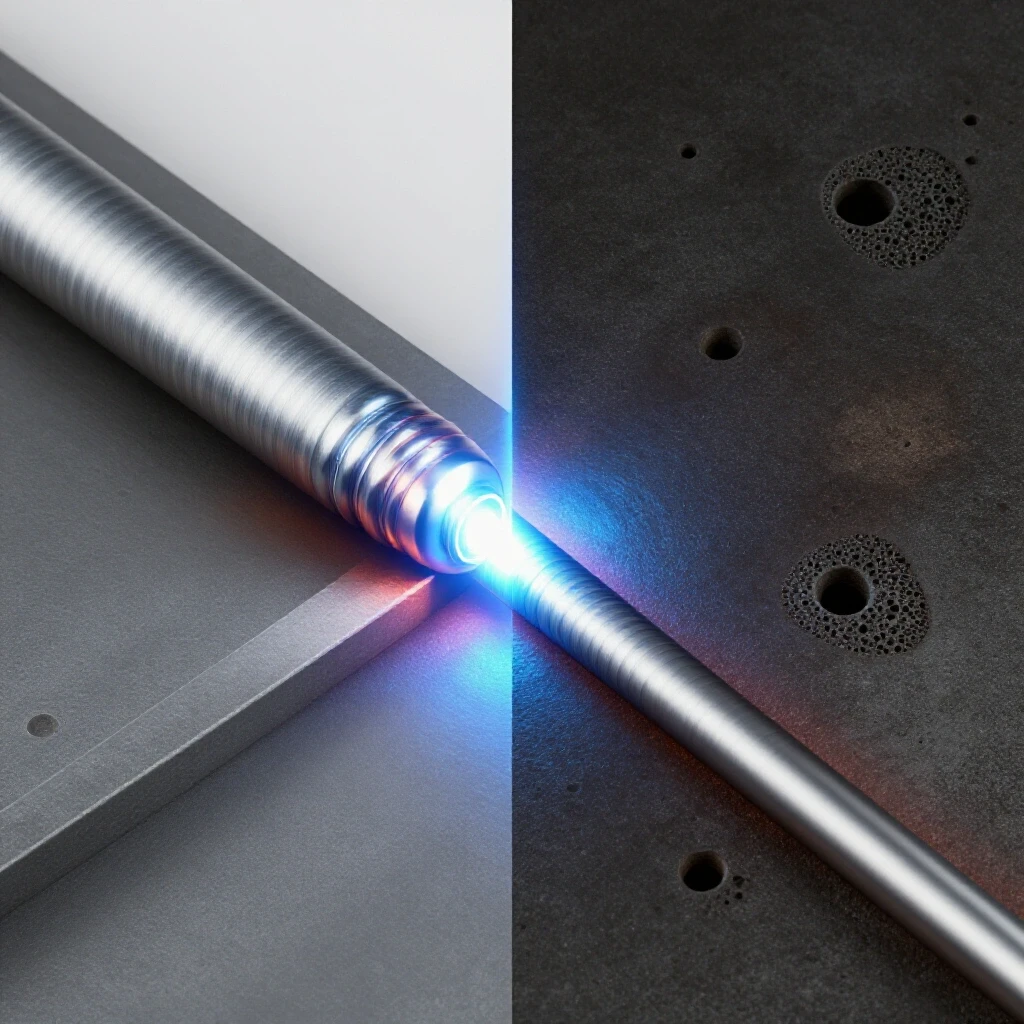
In my early years, I once spent an entire shift chasing what I thought was a faulty power supply, only to realize a micro-crack in the gas hose was siphoning in atmospheric air. That day taught me that diagnostics start at the source and move toward the arc. We are looking for the “why” behind the defect. Whether it is the “Swiss cheese” look of gas porosity or the jagged lines of a solidification crack, every flaw tells a story about what went wrong in the machine or the preparation.
Establishing a Systematic Diagnostic Framework for Aluminum TIG
A structured diagnostic framework is the only way to resolve intermittent welding issues without wasting expensive material and gas. We begin by observing the arc and the puddle, then we isolate the gas system, the electrical settings, and finally the material preparation. This process of elimination ensures no variable is overlooked.
When I walk into a shop to help a fabricator, I start with a clean slate. We don’t assume the gas is pure or the tungsten is sharp. We verify. This methodical approach relies on three pillars: observation, isolation, and variable control. By changing only one factor at a time—such as the shielding gas flow rate or the AC balance—we can see exactly how that change affects the weld bead. If you change three things at once and the problem goes away, you still don’t know what the problem was, and it will eventually return.
Step 1: Visual Observation and Symptom Mapping
Before touching any tools, we must categorize the defect based on its appearance and when it occurs during the weld cycle. Visual mapping allows us to narrow down the likely cause to either a mechanical, electrical, or chemical failure.
Different defects leave unique fingerprints. For instance, surface-level “pepper” usually points toward dirty filler rod or base metal, while deep, internal voids often suggest a shielding gas issue. I use a high-magnification loupe to inspect the “toes” of the weld. If I see a lack of fusion combined with a dull, grey surface, I know my cleaning action is insufficient. This initial mapping saves hours of unnecessary teardowns by pointing us toward the most probable failure point.
Step 2: Isolating the Shielding Gas Delivery System
Shielding gas issues are the most common cause of aluminum weld defects, yet they are often the most difficult to pin down. We must test the entire path from the cylinder regulator to the torch nozzle to ensure a laminar flow of pure argon.
I always check for the “venturi effect,” where a loose fitting actually sucks air into the gas stream rather than leaking gas out. This is a common “electrical gremlin” of the gas world. We use a dedicated flowmeter at the torch nozzle—not just the regulator—to verify that what the machine says it is delivering is actually reaching the puddle. A reading of 15 to 20 CFH (Cubic Feet per Hour) is usually the sweet spot, but even a slight draft in the shop can disrupt this envelope.
Step 3: Verifying Electrical and Inverter Parameters
Modern inverter machines offer a level of control that can be a double-edged sword. We must verify that the AC frequency, balance, and amperage are calibrated to the thickness of the material and the specific alloy being joined.
If the AC balance is set too high on the electrode negative side, you won’t get enough “cleaning” to break through the aluminum oxide layer. Conversely, too much electrode positive will overheat your tungsten and cause it to “spit” into the puddle. I typically start at 70% to 75% Electrode Negative (EN) and adjust in 2% increments. This level of precision is what separates a professional repair from a temporary fix.
Identifying and Resolving Aluminum Porosity
Porosity in aluminum TIG welding appears as small holes or voids within the weld metal, often caused by trapped hydrogen or atmospheric contamination. This defect weakens the joint significantly and is usually the result of improper gas coverage or contaminated base materials.
In my experience, hydrogen is the primary enemy. Aluminum has a high solubility for hydrogen when liquid, but almost none when solid. As the puddle freezes, the gas is pushed out, creating bubbles. If those bubbles don’t reach the surface before the metal solidifies, you get porosity. Troubleshooting this requires a deep dive into your gas purity and your cleaning habits.
Identifying the Source of Gas Contamination
Gas contamination can occur at the bottle, through the hoses, or at the torch itself. We must determine if the contamination is “upstream” or “downstream” by performing a series of static tests on a clean piece of scrap.
- Upstream Issues: These are usually contaminated gas cylinders or faulty regulators. If you swap the bottle and the problem persists, the issue is downstream.
- Downstream Issues: These include cracked O-rings in the torch head, loose back caps, or moisture inside the lead hoses. I have seen many fabricators struggle with porosity for days, only to find a tiny nick in the torch insulator that was letting air in.
| Symptom | Probable Cause | Diagnostic Test |
|---|---|---|
| Uniformly distributed voids | Contaminated shielding gas | Swap cylinder with a known pure source |
| Voids at the start of the weld | Insufficient pre-flow | Increase pre-flow to 1.0 – 1.5 seconds |
| Voids at the end of the weld | Insufficient post-flow | Increase post-flow to 1 second per 10 amps |
| Localized “pepper” spots | Dirty filler rod or base metal | Wipe filler with acetone and use a stainless brush |
Optimizing Shielding Gas Flow Dynamics
The way gas exits the nozzle is just as important as the gas itself. We need to ensure the flow is laminar (smooth) rather than turbulent, which can pull in outside air and cause oxidation.
Using a gas lens is one of the best ways to stabilize the flow. A standard collet body creates a chaotic “plume,” while a gas lens uses a series of fine meshes to straighten the gas. I recommend a #7 or #8 nozzle for most work. If your flow rate is too high—say, over 25 CFH—the gas can actually become turbulent and bounce off the workpiece, drawing in the very air you are trying to exclude.
Managing Oxide Inclusions and Cleaning Action
Oxide inclusions are fragments of the aluminum’s surface skin that become trapped inside the weld. Because aluminum oxide melts at roughly 3,700°F while the aluminum itself melts at 1,200°F, the oxide stays solid and sinks into the molten pool if not properly managed.
The “cleaning action” of the AC arc is what blasts this oxide away. This happens during the Electrode Positive (EP) half of the AC cycle. If you see a dark, scaly film on top of your bead, your cleaning action is failing. This is a common issue when fabricators try to weld “dirty” or weathered aluminum without adjusting their machine settings to compensate for the thicker oxide layer.
Adjusting AC Balance for Optimal Surface Cleaning
AC balance controls the ratio between the cleaning cycle and the penetration cycle. Finding the right balance is a trade-off between a clean weld and a deep, narrow penetration profile.
- Too Much Cleaning (High EP): The tungsten will ball up excessively, the arc will widen, and the heat-affected zone (HAZ) will become massive. You will see a very wide “frosted” zone around the weld.
- Too Little Cleaning (High EN): The arc will struggle to break the surface tension of the puddle. You will see “floaters” or black specks dancing on the molten metal.
I find that for most 6061-T6 aluminum, an AC balance of 72% EN provides the perfect compromise. If the material is cast or particularly old, I might drop it to 65% EN to increase the cleaning time.
Mechanical and Chemical Cleaning Protocols
You cannot rely on the arc alone to do all the cleaning. A systematic approach to material preparation reduces the “load” on the AC balance and results in a much cleaner internal structure.
- Degrease: Always use a non-chlorinated degreaser like acetone. Never use brake cleaner, as the heat of the arc can turn it into phosgene gas.
- Mechanical Abrasion: Use a dedicated stainless steel wire brush that has never touched steel or stainless. Brush in one direction only to avoid folding oxides back into the metal.
- Edge Prep: Don’t forget the edges. If you are doing a butt weld, the “face” of the cut needs as much cleaning as the top surface.
Troubleshooting Arc Instability and Tungsten Issues
Arc instability often manifests as a wandering arc, a flickering light, or a sudden “pop” that throws a black speck into the puddle. This is usually an electrical or mechanical issue related to the electrode preparation or the high-frequency start system.
When the arc isn’t stable, you lose control over the heat input. This leads to inconsistent penetration and can even cause the tungsten to touch the puddle. In my diagnostic logs, I’ve found that 90% of arc wandering is caused by either a contaminated tungsten or an incorrect electrode grind angle. Aluminum requires a specific geometry to handle the rapid switching of the AC cycle.
Selecting and Preparing the Tungsten Electrode
For modern inverter machines, the old rule of using pure tungsten (green tip) is dead. We now use alloyed electrodes like 2% Ceriated (grey) or 2% Lanthanated (blue) because they hold a point better under the stress of AC.
I grind my tungsten to a sharp point, then put a very small “land” or flat spot on the tip (about 0.010 to 0.020 inches). This prevents the very tip from breaking off and falling into the weld during the first high-amperage start. If you see the arc spinning around the tip of the tungsten, your point is likely too sharp or your AC frequency is set too low.
The Role of AC Frequency in Arc Focus
AC frequency, measured in Hertz (Hz), determines how many times per second the current switches directions. Most older machines are fixed at 60 Hz, but modern inverters allow you to go up to 200 Hz or more.
- Low Frequency (60-80 Hz): Produces a wide, soft arc. Good for heavy plate where you need a large puddle.
- High Frequency (100-150 Hz): Produces a tight, focused arc. This is essential for thin gauge material or inside corners where you need to direct the heat precisely.
If you are experiencing “arc blow” or the arc is jumping to the sides of a V-groove, increasing the frequency to 120 Hz will usually pull the arc into a tighter column and solve the problem.
Preventing Solidification Cracking and Crater Defects
Solidification cracking, often called “hot cracking,” happens as the weld metal shrinks during cooling. Because aluminum has a high coefficient of thermal expansion, it shrinks significantly more than steel, putting immense stress on the cooling bead.
The most vulnerable part of any aluminum weld is the “crater” at the end of the run. If you suddenly snap the torch away, the puddle cools too fast, shrinks, and cracks right down the middle. I have seen these cracks propagate several inches through a structural member, turning a minor defect into a major failure.
Crater Fill Techniques and Tail-Out Procedures
Preventing crater cracks is a matter of technique and machine settings. We must “taper” the heat at the end of the weld to allow the puddle to solidify slowly.
I use a “down-slope” setting on my machine of about 2 to 3 seconds. As I reach the end of the joint, I add a final dab of filler rod to make the crater slightly convex (humped up) rather than concave (sunken). A concave crater is a structural weak point that is almost guaranteed to crack. By filling the crater and slowly backing off the amperage, we distribute the shrinkage stresses more evenly.
Filler Metal Selection and Dilution Ratios
Choosing the wrong filler rod is a common diagnostic dead end. The chemistry of the filler must be compatible with the base metal to avoid a “crack-sensitive” chemistry in the puddle.
- 4043 Filler: Contains about 5% silicon. It flows well and is very resistant to cracking, but it doesn’t anodize well (it turns dark grey).
- 5356 Filler: Contains about 5% magnesium. It is stronger and stiffer than 4043 and keeps its color after anodizing, but it is more prone to cracking if the cooling rate isn’t managed.
If I am welding a 6000-series aluminum and I see centerline cracking despite good technique, I immediately check my filler. Switching from 5356 to 4043 often resolves the issue because the silicon in 4043 lowers the melting point and helps “fill” the gaps as the weld solidifies.
Advanced Diagnostic Tools for the Modern Fabricator
While a good eye is your best tool, modern technology has given us several ways to verify what is happening inside the machine and the material. These tools remove the guesswork from the troubleshooting process.
- Digital Gas Flowmeter: Measures actual flow at the nozzle in liters per minute or CFH.
- Infrared Thermometer: Essential for checking preheat temperatures. If the aluminum is over 200°F, the puddle behavior changes significantly.
- Smartphone Vibration Apps: Can be used to check if shop machinery (like a nearby large press) is causing harmonic vibrations that affect arc stability.
- Digital Multimeter: Used to check for “ground loops” or poor work-clamp connections that cause voltage drops.
Case Study: The Mystery of the “Fuzzy” Arc
I once worked with a fabricator who was getting a “fuzzy,” unstable arc on 1/4″ plate. We checked the gas, the tungsten, and the settings. Everything looked perfect. We finally used a multimeter to check the resistance between the work clamp and the table.
We found a 0.5-ohm resistance because the table’s pivot point was covered in old grease. This tiny resistance was enough to interfere with the high-frequency signal. We moved the clamp directly to the workpiece, and the arc instantly smoothed out. It was a classic example of how a mechanical alignment issue (the table joint) can manifest as a welding defect.
Actionable Tracking Framework: The 5-Point Check
When you encounter a defect, go through this checklist before making any major changes to your setup.
- Check Gas: Is the bottle empty? Is the flowmeter at the torch reading 17 CFH?
- Check Tungsten: Is it contaminated? Is the grind longitudinal (parallel to the electrode)?
- Check Ground: Is the work clamp on clean metal? Is there a direct path to the weld?
- Check Material: Was it wiped with acetone? Was the oxide layer brushed off?
- Check Settings: Is the AC balance at 70-75%? Is the frequency appropriate for the joint?
By following this hierarchy, you isolate the most common points of failure. Most issues are found in the first three steps. If you reach step five and the problem persists, it is time to look at the machine’s internal electronics or the gas purity itself.
Frequently Asked Questions
Why does my aluminum weld have black specks (pepper) in it?
Black specks are usually a sign of surface contamination. This happens when the oxide layer wasn’t fully removed, or the filler rod was dirty. The “pepper” is actually bits of aluminum oxide or hydrocarbons being trapped in the puddle. To fix this, use a dedicated stainless steel brush and wipe both the base metal and the filler rod with acetone right before welding.
What is the best AC balance setting for general aluminum work?
For most modern inverter machines, a balance of 70% to 75% Electrode Negative (EN) is the standard. This provides a good mix of deep penetration and enough cleaning action to keep the puddle clear. If you are welding very old or cast aluminum, you may need to drop to 60-65% EN to increase the cleaning time.
How can I tell if my argon gas is contaminated?
The easiest way is the “puddle test” on a piece of clean scrap. Sharpen your tungsten, set your machine to DCEN (like you are welding steel), and strike an arc on a clean piece of stainless steel. If the spot is bright and shiny, the gas is pure. If the spot is dull, grey, or has a “rainbow” soot around it, your gas is contaminated or you have a leak in your lines.
Why is my tungsten balling up and melting?
This is usually caused by having too much “Electrode Positive” (EP) in your AC balance or using a tungsten that is too thin for the amperage. On an inverter, your tungsten should stay relatively sharp with just a slight rounding at the tip. If it turns into a large ball, increase your EN percentage (e.g., move from 60% to 75%).
What causes a crack to form right down the middle of my weld?
This is called a centerline solidification crack. It happens because the weld is shrinking as it cools and the metal isn’t strong enough to hold together. This is common in 6000-series aluminum. To prevent it, try using 4043 filler rod instead of 5356, and make sure you aren’t making the weld bead too thin or concave.
How much gas flow is too much for aluminum TIG?
Anything over 25-30 CFH can actually cause problems. High flow rates create turbulence at the nozzle, which pulls in atmospheric air (oxygen and nitrogen) into the gas stream. This is called the venturi effect. Stick to 15-20 CFH for most standard nozzles.
Why does the arc wander when I am welding in a corner?
This is usually due to “arc blow” or the arc following the path of least resistance. In a corner, the magnetic fields can get crowded. To fix this, increase your AC Frequency to 120-150 Hz. This tightens the arc column and forces it to go where the tungsten is pointing rather than jumping to the sides.
Do I really need to use a gas lens?
While not strictly required, a gas lens is highly recommended for aluminum. It provides a much more stable, laminar flow of gas, which allows for better visibility and more consistent cleaning action. It also allows you to have a longer tungsten stick-out, which helps when welding in tight spots.
How do I prevent the “crater” at the end of the weld from cracking?
Never stop the arc abruptly. Use your foot pedal to slowly back off the heat while adding a final dab of filler rod. This “fills” the shrinkage void. If your machine has a “down-slope” setting, set it to 2 or 3 seconds to automate this tapering process.
Can I use the same wire brush for aluminum and steel?
No. You must have a dedicated stainless steel brush for aluminum only. If you use a brush that has touched steel, you will embed tiny particles of carbon steel into the aluminum. These particles will cause “pepper” in your weld and will eventually lead to galvanic corrosion.
(This article was written by one of our staff writers, Paul Whitaker. Visit our Meet the Team page to learn more about the author and their expertise.)