How to Manage Welding Heat Input on Alloy Steel (DIY Guide)
I have spent fifteen years in workshops, often hunched over a piece of equipment that refuses to behave. There is a specific kind of frustration that sets in when you are working with high-strength alloy steels and a weld that looked perfect suddenly pings and cracks as it cools. It is not just about the arc or the bead; it is about the invisible energy moving through the metal. When I first started as a millwright, I thought more power meant better penetration. I was wrong. I quickly learned that alloyed metals are sensitive, and if you do not respect the thermal energy you are pumping into them, the material will fight back with warping, cracking, or brittle failures.
Mastering the way energy interacts with these metals requires a shift from “guessing” to “measuring.” In my experience, most fabrication failures do not happen because of a lack of skill, but because of a lack of a systematic diagnostic process. Whether you are fixing a cracked hitch, a worn-out shaft, or a custom bracket, you have to treat the metal like a living thing that reacts to every degree of temperature change. This guide is built on the lessons I have learned the hard way, through thousands of hours of troubleshooting and repair.
Establishing a Diagnostic Framework for Thermal Control
A metalworking diagnostic guide must begin with a structured way to look at the variables of your project. Troubleshooting thermal issues in alloyed metals involves isolating the electrical settings of your machine from the physical movement of your hand. By breaking down the process into observable steps, you can identify why a part is distorting or why the grain structure is failing.
When I approach a new repair, I start by mapping out the “energy footprint.” This means looking at how much electricity is being converted into heat and how fast that heat is moving across the part. Alloy steels, like 4140 or 4340, have a high hardenability. This means they want to turn brittle if they cool too fast or get too hot. To manage this, I use a high-level diagnostic framework: observation of the arc, isolation of the power variables, and control of the cooling rate.
- Observation: Look for the width of the heat-affected zone (HAZ). A wide, blue-tinted area usually indicates you are moving too slowly or your amperage is too high.
- Isolation: Check your machine’s actual output. I have seen many cases where a dial says 120 amps, but a clamp meter shows 145.
- Variable Control: Change only one thing at a time. If you change your travel speed and your voltage at once, you will never know which one solved the problem.
Why Material Cracking and Warping Occur in High-Strength Alloys
Alloy steels contain elements like chromium, molybdenum, and manganese that change how the metal reacts to a torch. When you introduce thermal energy, these elements can cause the metal to harden significantly in the area right next to the weld. If the energy input is too high, the grain structure grows too large, making the joint weak and prone to “underbead cracking.”
I remember troubleshooting a persistent cracking issue on a heavy equipment arm made of a low-alloy, high-strength steel. The fabricator was doing everything “by the book,” but the welds kept failing. After a few hours of observation, I realized the interpass temperature was climbing way too high. The metal never had a chance to settle between beads. We were essentially cooking the alloy, destroying its mechanical properties. By implementing a strict cooling limit between passes, the cracking stopped immediately. This is why understanding the “why” behind the metal’s reaction is just as important as the “how” of the weld.
Calibrating Machine Parameters for Precise Energy Delivery
Troubleshooting weld porosity and inconsistent fusion often leads back to the stability of the power source. If your wire feeder is pulsing or your voltage is surging, the energy density of the arc fluctuates. For alloy steels, these fluctuations are catastrophic because they create “hot spots” where the alloying elements can segregate or “cold spots” where the metal doesn’t fuse properly.
To get a baseline, I always perform a mechanical check of the equipment. I look for a backlash of no more than 0.002 inches in any geared drive systems and ensure the wire feed rolls have a consistent tension. If the wire slips even for a fraction of a second, the arc length changes, the voltage spikes, and you’ve just dumped an uncontrolled amount of energy into the part.
| Variable | Target Metric | Diagnostic Sign of Failure |
|---|---|---|
| Voltage (V) | +/- 0.5V of Setting | Wandering arc or excessive spatter |
| Amperage (A) | Consistent with Wire Speed | Inconsistent penetration or “cold laps” |
| Travel Speed | 10-15 inches per minute | Wide HAZ or narrow, ropy beads |
| Gas Flow Rate | 25-30 CFH | Porosity or dark, oxidized weld surface |
Isolating Tool Chatter and Vibrational Interference
Mechanical troubleshooting steps often reveal that weld defects aren’t just about the arc. If your workpiece is not rigidly clamped, or if your shop floor has heavy machinery causing floor vibrations, you can experience arc instability. This is often mistaken for an electrical issue, but it is actually a mechanical one. Vibrations can cause the contact tip-to-work distance to oscillate, which in turn causes the current to fluctuate.
In one shop I visited, the welder was struggling with “arc blow”—where the arc wanders uncontrollably. We checked the gas, the wire, and the ground. Nothing worked. It turned out that a large lathe ten feet away was creating a harmonic vibration in the long, thin alloy plate he was welding. This vibration was just enough to disturb the ionized path of the arc. We dampened the plate using heavy C-clamps and scrap lead weights, and the “electrical” problem vanished.
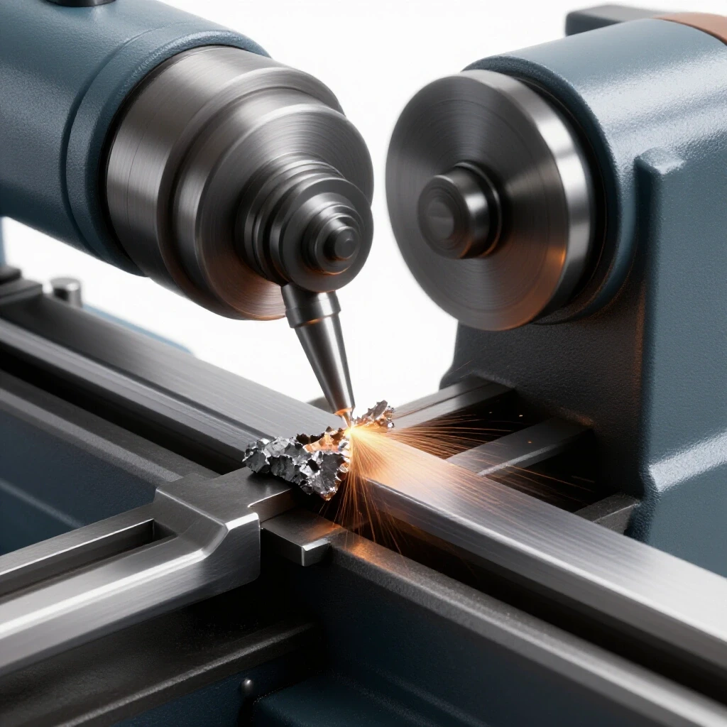
- Check for Spindle Play: If you are prep-machining your alloy parts, ensure the lathe or mill has less than 0.001 inches of runout.
- Isolate Grounding: A loose ground clamp can create a “micro-arcing” situation that looks like tool chatter in the weld bead.
- Dampen Resonance: Use sandbags or heavy clamps on long alloy sections to stop the metal from “ringing” during the process.
The Math of Energy: Calculating Heat Input
To truly master the fusion of alloyed metals, you have to move beyond “feel” and start using the standard formula for energy delivery. This is the only way to ensure you are staying within the limits that the material can handle. The formula is simple: (Amps x Volts x 60) / (Travel Speed in inches per minute). The result is Joules per inch.
I once worked on a project involving 4340 steel shafts. The spec called for a maximum energy input to avoid softening the heat-treated core. By timing my travel speed with a stopwatch and recording my average voltage, I found I was putting in 45,000 Joules per inch, which was 10,000 too high. By increasing my travel speed and using a “stringer bead” technique instead of a wide weave, I dropped the energy input to 32,000 Joules per inch, and the shafts passed every inspection.
- Measure Amps and Volts: Do not trust the machine dials; use a multimeter if possible.
- Time Your Travel: Mark a 12-inch line on scrap and time how long it takes to weld it.
- Calculate: Use the formula to find your baseline Joules per inch.
- Adjust: If the metal is warping or cracking, your goal is to lower that number by increasing speed or lowering amperage.
Managing Preheat and Interpass Temperatures
One of the most common metal fabrication fixes for alloy steel is simply slowing down the cooling rate. Alloy steels are “air-hardening,” meaning they can become as brittle as glass if they cool too fast from welding temperatures. Preheat is the “buffer” that prevents this. It slows down the cooling rate of the weld and the HAZ, allowing the hydrogen to escape and the grain structure to form more slowly.
I use Tempil sticks or an infrared thermometer to track this. For most medium-alloy steels, a preheat of 250°F to 400°F is a safe starting point. However, you must also monitor the “interpass temperature”—the temperature of the metal between each weld bead. If the part gets hotter than 600°F, you risk over-tempering the alloy and losing the very strength you bought the metal for in the first place.
- Preheat Method: Use a propane torch to soak the metal until the heat is uniform, not just on the surface.
- Monitoring: Check the temperature about one inch away from the joint.
- Cooling: Never quench an alloy steel weld in water. Wrap it in a welding blanket or bury it in dry sand to let it cool slowly over several hours.
Troubleshooting Weld Porosity in Alloyed Metals
Porosity is the “hidden enemy” of the fabricator. In alloy steels, it is often caused by hydrogen being trapped in the cooling metal. This hydrogen can come from moisture in the air, grease on the metal, or even the coating on the welding wire. When troubleshooting weld porosity, I follow a “path of elimination” that starts at the bottle and ends at the puddle.
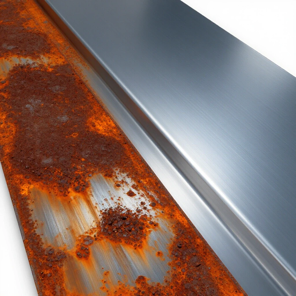
First, I check the gas flow. If it is too high (over 40 CFH), it creates turbulence that pulls in outside air. If it is too low (under 15 CFH), it doesn’t shield the puddle. Next, I look at the material prep. Alloy steels are notorious for having a “mill scale” that traps contaminants. I grind every joint to shiny metal at least one inch back from the weld. Finally, I check the electrical path. A poor ground can cause a “fluttering” arc that allows the shielding gas to be blown away.
A Case Study in Systematic Repair: The 4140 Drive Shaft
A few years ago, I was asked to repair a 4140 chromoly drive shaft that had snapped. The owner had tried to weld it twice, and both times it cracked within an inch of the weld after a few hours of use. This was a classic case of failing to manage thermal energy.
I started by performing a lathe alignment checklist to ensure the two pieces were perfectly centered. I found 0.015 inches of runout, which would have caused a massive vibration (tool chatter) once the shaft was spinning. After aligning the parts to within 0.002 inches, I began the thermal process. I preheated the shaft to 450°F. I used a low-hydrogen filler metal and kept my beads small—no weaving. I monitored the interpass temperature, never letting it exceed 550°F. After the weld was finished, I wrapped the entire shaft in a heavy ceramic blanket. The shaft has been in service for three years now without a single issue. The difference wasn’t the welder; it was the process.
Essential Diagnostic Tools for the DIY Shop
To move from guesswork to professional-grade troubleshooting, you need a few specific tools. These allow you to see what is happening to the metal and the machine in real-time.
- Infrared Thermometer: Essential for tracking preheat and interpass temperatures accurately.
- Digital Dial Indicator: Used for checking machine alignment and part runout to prevent vibrational issues.
- Clamp-on Ammeter: To verify the actual electrical output of your welding power source.
- Magnifying Loupe (10x): To inspect the toes of a weld for tiny “stress risers” or micro-cracks.
- Stopwatch: For calculating travel speed and energy input.
Actionable Tracking Framework: The Weld Log
I highly recommend keeping a log for every complex alloy project. This isn’t just paperwork; it is a diagnostic tool. If a part fails, you can look back and see exactly what the temperature was or how fast you were moving.
- Material Grade: (e.g., 4140, 4340, 8620)
- Preheat Temp: (Measured in degrees Fahrenheit)
- Voltage/Amps: (Actual measured values, not dial settings)
- Travel Speed: (Seconds per inch)
- Interpass Temp: (Maximum temperature reached between beads)
- Cooling Method: (Blanket, sand, or still air)
Conclusion: The Path to Permanent Repairs
Mastering the thermal dynamics of alloy steels is a journey of patience and precision. It requires you to stop looking at welding as just “sticking two pieces of metal together” and start seeing it as a complex metallurgical event. When you take the time to calculate your energy input, monitor your temperatures, and ensure your machinery is mechanically sound, the “mysterious” problems like cracking and warping start to disappear.
The most important lesson I have learned in fifteen years is that the metal never lies. If it cracks, it is telling you that the cooling was too fast or the energy was too high. If it warps, it is telling you that the heat was too concentrated. By using a systematic diagnostic approach, you can listen to what the material is telling you and make the necessary adjustments to ensure a permanent, high-quality repair every time.
Frequently Asked Questions
How do I know if I am putting too much heat into the metal? The most visible sign is the width and color of the heat-affected zone (HAZ). If the blue or straw-colored band extends more than a quarter-inch from the weld bead on thin material, your energy input is likely too high. Additionally, if the weld puddle becomes very fluid and difficult to control, or if the bead is very flat and wide, you should increase your travel speed or lower your amperage.
Why does my alloy steel weld crack even after I preheated it? Cracking after preheating usually points to one of two things: the interpass temperature got too high, or the cooling process was too fast. If the metal stays too hot for too long, the grains grow large and weak. Conversely, if you preheated it but then let it sit in a cold draft after welding, the “thermal shock” can still cause hydrogen-induced cracking. Always wrap the finished part to ensure a slow, uniform cool-down.
Can I weld alloy steel with a standard MIG welder? Yes, but you must use the correct shielding gas and filler wire. For many alloys, a high-argon mix is needed to keep the arc stable and the heat concentrated. You must also be more diligent about your travel speed, as MIG can easily dump a lot of energy into a joint very quickly. Using a “pulsed” setting, if your machine has it, can help manage the thermal load.
What is the best way to clean alloy steel before welding to prevent porosity? Grinding is the only reliable method. Use a clean zirconia or ceramic grinding disc to remove all mill scale, rust, and oils until the metal is bright and shiny. Avoid using “flapper” discs that can sometimes smear contaminants into the surface. After grinding, a quick wipe with acetone (on a clean rag) will remove any remaining fingerprints or oils.
How does machine vibration affect my weld quality? Vibration, or “tool chatter,” causes the distance between your welding tip and the workpiece to change rapidly. This creates fluctuations in the electrical resistance of the arc, leading to “spiking” in the energy input. This can cause intermittent fusion, increased spatter, and a jagged bead appearance. Ensuring your workpiece is rigidly supported is a critical mechanical troubleshooting step.
Is an infrared thermometer accurate enough for welding? For most DIY and workshop applications, a high-quality infrared thermometer is excellent for tracking preheat. However, be aware that shiny, polished metal can give false readings. It is often better to paint a small “flat black” spot on the metal or use temperature-indicating crayons (Tempil sticks) to verify the thermometer’s accuracy on a specific material.
What happens if I don’t reach the required preheat temperature? If the metal is too cold, the weld area will act as a “heat sink,” sucking the energy out of the arc and causing the weld to cool instantly. This creates a brittle zone called “martensite,” which is prone to cracking under even light loads. If you can’t reach the full preheat, it is often better to wait until you have a larger heat source rather than risking a brittle failure.
How do I calculate travel speed if I don’t have a helper with a stopwatch? Mark a specific length, such as three inches, on your workpiece. As you weld, count “one-thousand-one, one-thousand-two” at a steady pace. With a little practice, you can get a very good sense of your inches-per-minute. Alternatively, record a video of your weld with your phone and use the video’s timestamp to calculate exactly how long it took to cover the distance.
Why is my ground clamp getting hot during the weld? A hot ground clamp is a sign of high electrical resistance. This means the energy that should be going into your weld is being wasted as heat at the clamp. This causes an unstable arc and inconsistent energy delivery to the alloy. Clean the area where the clamp attaches to “white metal” and ensure the clamp has strong spring tension or a bolted connection.
What is the “stringer bead” technique and why is it better for alloys? A stringer bead is a straight weld with little to no side-to-side oscillation (weaving). It is preferred for alloy steels because it keeps the arc moving forward quickly, which minimizes the amount of time any single spot is exposed to high heat. This keeps the heat-affected zone narrow and helps maintain the mechanical properties of the base metal.
(This article was written by one of our staff writers, Paul Whitaker. Visit our Meet the Team page to learn more about the author and their expertise.)