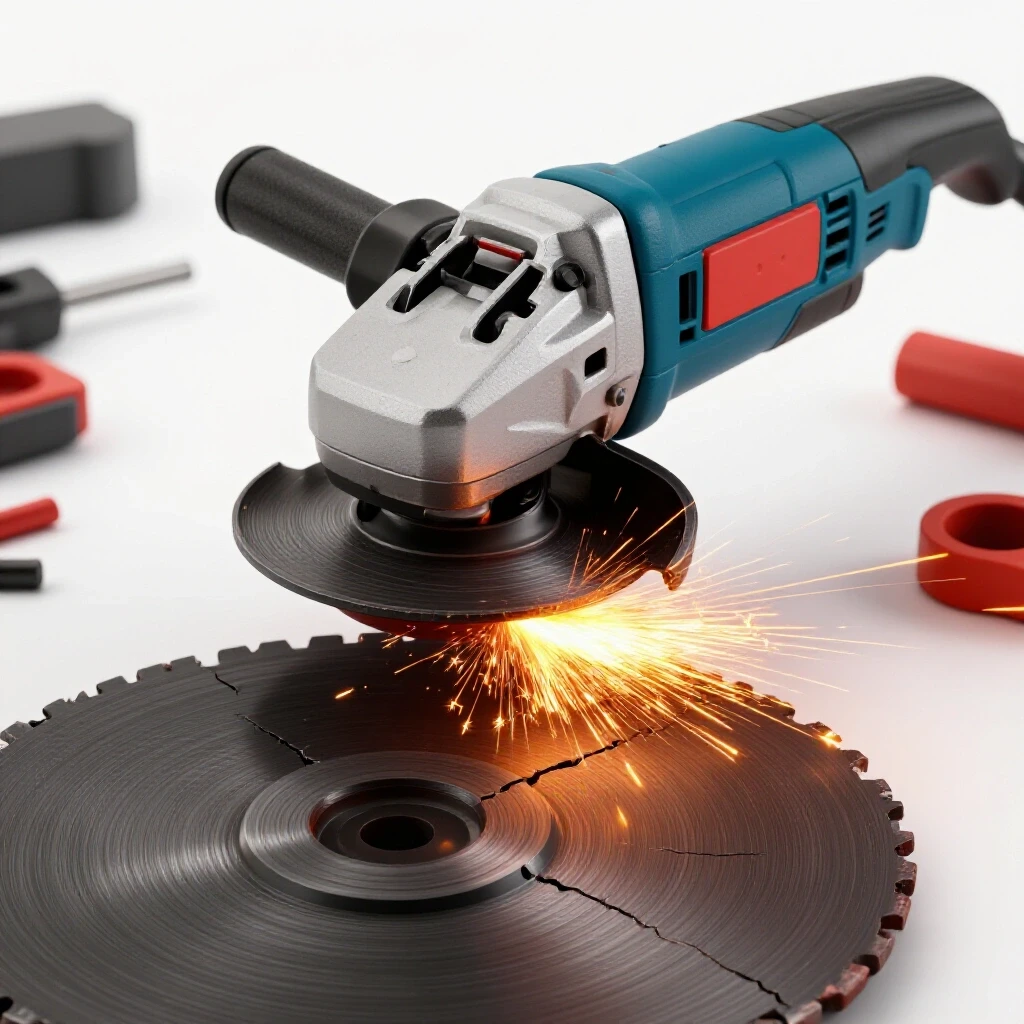
How to Replace Worn Bearings in Bench Grinder Motors (Fix)
A few years ago, I walked into a small fabrication shop where the owner was ready to scrap a high-quality 8-inch bench grinder. He complained that the machine vibrated so much it was “walking” across his workbench, and the noise was a high-pitched growl that made conversation impossible. He assumed the motor was shot. After eighteen years of troubleshooting industrial machinery, I’ve learned that the most dramatic symptoms often have the most straightforward mechanical causes. We didn’t scrap it. Instead, we spent an hour diagnosing and resolving the internal friction issues that were robbing the tool of its precision.
When a piece of equipment you rely on daily starts to fail, the instinct is often to work around the problem or replace the unit entirely. In a busy shop, downtime is the enemy of profit. However, jumping to conclusions without a systematic diagnostic process usually leads to wasted money. Whether you are dealing with tool chatter during a critical sharpening task or noticing a rough finish on a fabricated part, the root cause is frequently found in the small, rotating components that support the motor’s internal shaft.
In this guide, I will walk you through the methodical process of identifying, removing, and replacing the internal supports of a standard single-phase motor. We will focus on the mechanical aspects of the teardown and the precision required to restore a smooth, quiet rotation. By the end, you will have a structured framework for maintaining your shop’s rotating equipment, ensuring your tools remain as reliable as your craftsmanship.
Diagnosing Mechanical Noise and Rotational Vibration
Identifying the source of rhythmic disturbances before tearing down the machine is the first step in any successful repair. It prevents you from fixing things that aren’t broken and focuses your energy on the actual failure point.
When a grinder begins to vibrate or hum excessively, you must isolate the variables. In my experience, vibration is rarely a single-factor issue. It is a combination of mass, speed, and support. To begin, I perform a “run-down test.” Turn the motor on, let it reach full RPM, and then cut the power. Listen closely as the speed drops. If the vibration and noise continue until the shaft stops, you are dealing with a mechanical failure in the rotating assembly, not an electrical fault.
Distinguishing Between External Imbalance and Internal Wear
Using isolation steps helps determine if the issue is caused by the abrasive wheels themselves or the internal components supporting the rotor. This is a critical distinction that saves hours of unnecessary labor.
I always start by removing the grinding wheels, flanges, and guards. If the bare motor shaft still vibrates or makes a grinding sound when spun by hand, the internal supports—the bearings—are the culprit. A healthy motor should spin freely with a soft, “whirring” sound. If you feel any “notchy” resistance or hear a metallic clicking, the internal races have likely been compromised by dust or fatigue.
Measuring Shaft Run-out and Play
Quantifying the physical movement of the motor shaft provides a baseline for the repair. This moves the diagnosis from “it feels loose” to “it is out of tolerance by 0.005 inches.”
Using a digital dial indicator, I check for both radial and axial play. Radial play is the side-to-side movement of the shaft, while axial play is the back-and-forth movement along the length of the motor. For most shop-grade motors, radial play should be nearly imperceptible—typically less than 0.001 to 0.002 inches. If your indicator shows a jump of 0.005 inches or more, the internal support has reached the end of its service life. This excessive play is a primary cause of tool chatter, as the shaft “bounces” within the housing during operation.
| Symptom | Probable Cause | Diagnostic Action |
|---|---|---|
| High-pitched squealing | Lack of lubrication/Dry races | Check for heat buildup at end caps |
| Deep, rhythmic growling | Pitting or “Brinelling” on races | Perform manual rotation test |
| Excessive shaft heat | Internal friction/Pre-load issue | Use infrared thermometer (>140°F is high) |
| Visible shaft wobble | Worn internal bore or bent shaft | Measure with dial indicator |
The Systematic Disassembly of the Motor Housing
The controlled breakdown of the motor casing is necessary to access the internal rotor. This stage requires patience, as forcing components can lead to cracked cast-iron housings or stripped threads.
Before any tools touch the motor, I follow a strict lockout/tagout procedure. Unplug the unit and verify that the power is dead. In a shop environment, “thinking” it is unplugged isn’t enough; physical verification is the only way to ensure safety. Once the machine is safe, I clear a wide, clean space on my bench. I use a series of small containers to hold the fasteners from each side of the motor, labeling them “Left” and “Right” to avoid confusion during reassembly.
Removing External Hardware and End Shields
Ensuring the workspace is organized is vital for a complex mechanical repair. This phase involves removing the protective covers and the structural end caps that hold the rotor in place.
Most bench grinders use long through-bolts that run the entire length of the motor body. Before loosening these, I use a center punch or a permanent marker to make “match marks” on the end shields and the main motor stator. This ensures that when I put it back together, the components are aligned exactly as they were at the factory. When removing the shaft nuts, remember the golden rule of grinders: the left side of the machine (as you face it) typically uses left-hand threads to prevent the nut from loosening during operation.
Separating the Rotor from the Stator
The rotor is the heavy, cylindrical center of the motor that spins. Removing it requires a steady hand to avoid damaging the delicate copper windings inside the motor housing.
Once the end shields are loose, I gently tap them with a rubber or plastic mallet. Never use a steel hammer here, as cast aluminum or iron end caps can crack easily. As the shields pull away, the rotor will want to “stick” to the inside of the motor due to magnetic pull. I slide the rotor out slowly, being careful not to let it drag against the internal wiring. Even a small scratch on the wire insulation can lead to a short circuit later.
Extracting the Worn Components from the Rotor Shaft
The process of removing pressed-on circular supports requires mechanical force. Using the wrong tool here can easily bend the rotor shaft, turning a simple repair into a total loss.
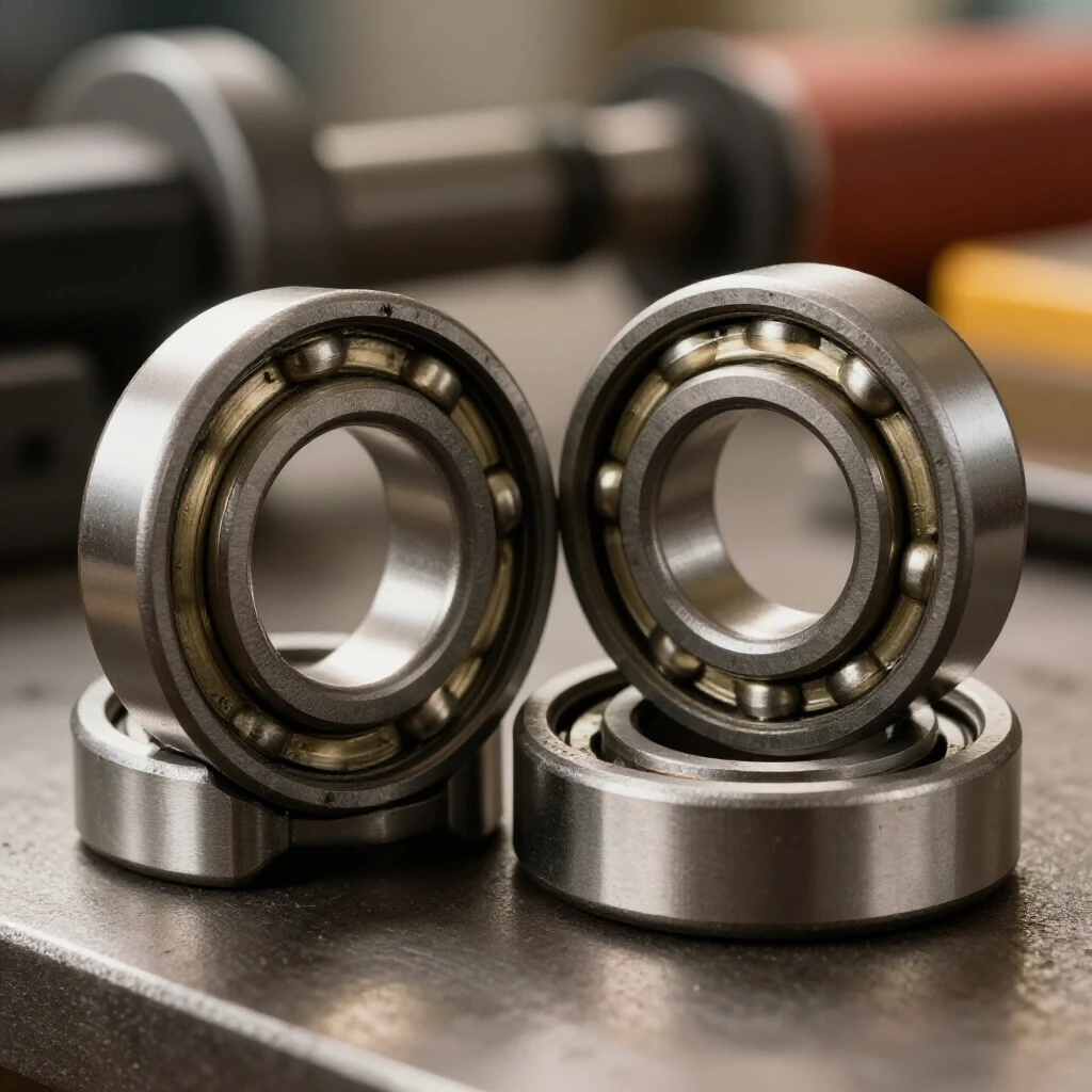
The bearings are usually “interference fit” onto the shaft, meaning they are slightly smaller than the shaft itself and are held on by friction. To remove them, you need a dedicated bearing puller. I prefer a three-jaw puller because it distributes the pulling force more evenly than a two-jaw version.
Using Mechanical Pullers with Precision
Choosing the right puller and applying force correctly ensures the inner race is pulled straight off the shaft without tilting.
I position the puller jaws behind the inner race of the bearing. If the jaws only grab the outer race, the bearing might pull apart, leaving the inner ring stuck on the shaft—a much harder problem to solve. I tighten the puller’s center bolt slowly. If it feels stuck, I don’t just crank on it. I might apply a small amount of penetrating oil or use a heat gun to slightly expand the bearing. The goal is a smooth, controlled slide. Once the bearing “pops” loose, it usually slides off with minimal effort.
Cleaning and Inspecting the Shaft Surfaces
Once the old parts are off, the shaft must be cleaned of all debris, old grease, and burrs. This ensures the new components sit perfectly square.
I use a fine Scotch-Brite pad or 400-grit emery cloth to polish the bearing seats on the shaft. I’m not trying to remove metal; I’m just removing the “varnish” left behind by the old lubricant. I also inspect the shaft for any signs of “spinning.” if the old bearing was loose enough to spin on the shaft, it might have worn the metal down. In that case, the new bearing won’t fit tightly, and you’ll need a specialized retaining compound to fill the gap.
Installing New Rotating Elements with Precision
Seating the replacements using controlled pressure or thermal expansion is the most delicate part of the process. If you damage the new bearing during installation, the motor will fail again within weeks.
When buying replacements, I always look for “sealed” bearings (usually designated by a “2RS” suffix). These come pre-lubricated and have rubber seals that keep out the fine metal dust and grit found in fabrication shops. This is a significant upgrade over the “shielded” (ZZ) versions often found in cheaper motors, which allow fine particles to enter the races.
Seating the Bearing Without Impact Damage
The key to a long-lasting repair is ensuring that the installation force is only applied to the race that is being fitted.
If you are pressing a bearing onto a shaft, you must only apply pressure to the inner race. If you push on the outer race, you force the tiny steel balls into the raceway, causing microscopic dents known as “brinelling.” I often use a piece of clean pipe or a deep-well socket that matches the diameter of the inner race perfectly. Using a shop press is ideal, but if you must use a hammer, use a series of light, even taps around the circumference of the driver tool.
Thermal Fitting Techniques
Using temperature differences can make the installation process much easier and reduce the risk of mechanical damage to the shaft.
If the fit is particularly tight, I use the “hot and cold” method. I place the rotor in the freezer for an hour to slightly shrink the steel shaft. Simultaneously, I can warm the new bearings in a small oven (not a microwave!) to about 150°F. This thermal expansion often allows the bearing to slide onto the shaft by hand, or with very little force. Once the temperatures equalize, the fit becomes incredibly tight and secure.
Reassembling the Motor and Verifying Performance
Putting the housing back together requires careful alignment to ensure the rotor is centered within the magnetic field of the motor.
I slide the rotor back into the stator, again being careful not to nick the windings. I align the end shields using the match marks I made earlier. When tightening the through-bolts, I use a “star pattern,” similar to tightening lug nuts on a car. This ensures the end caps pull down evenly and don’t cock the bearings at an angle.
Testing for Smooth Rotation and Run-out
The final check involves spinning the shaft by hand before applying power. It should feel smooth, silent, and have a long “coast” time.
Once the motor is back together, I re-check the shaft with my dial indicator. I’m looking for a total indicated run-out (TIR) of less than 0.002 inches. If the shaft is wobbling more than that, one of the end shields might be seated incorrectly. I also check the axial play. There should be a tiny amount of “end play” (usually 0.005 to 0.015 inches) to allow for the shaft to expand as it gets warm during use. If the shaft is too tight, the bearings will overheat and fail prematurely.
Initial Power-Up and Monitoring
The first run after a repair should be done without the grinding wheels attached. This allows you to monitor the motor’s behavior without the interference of wheel imbalance.
I turn the motor on and let it run for about ten minutes. During this time, I use an infrared thermometer to check the temperature of the end caps. They should be warm to the touch but not hot. If the temperature exceeds 140°F, the bearings might be over-preloaded or the housing might be misaligned. A successful repair will result in a motor that reaches its rated speed (usually 3450 RPM for a standard grinder) quickly and quietly.
Troubleshooting Framework and Maintenance Log
To avoid future downtime, I recommend keeping a simple log for every major tool in your shop. This turns “random” failures into a predictable maintenance schedule.
Systematic troubleshooting is about data. If you know that your grinder’s bearings lasted 2,000 hours of shop time, you can plan the next replacement before the machine fails. Use the following checklist to maintain your equipment:
- Weekly Vibration Check: Place a hand on the motor housing (while off) after a long run. Feel for unusual heat or “roughness.”
- Monthly Cleaning: Use compressed air to blow out the cooling vents. Metal dust is conductive and abrasive; keep it out of the motor.
- Quarterly Run-out Test: Use a dial indicator to check for developing play in the shaft.
- Annual Inspection: Disassemble the outer guards and check for any signs of grease leaking from the bearing seals.
Common Mistakes to Avoid
- Using a “Hammer Only” Approach: Impact is the enemy of precision bearings. Always use a driver or a press.
- Mixing Up Fasteners: Grinders often have a mix of SAE and Metric hardware, or left-hand and right-hand threads. Keep them organized.
- Over-tightening Guards: If the guards are distorted during reassembly, they can rub against the shaft or wheels, creating false “vibration” symptoms.
- Ignoring the “Match Marks”: If the end caps are rotated 180 degrees from their original position, the internal alignment may be slightly off, leading to heat buildup.
FAQ: Common Questions on Motor Bearing Maintenance
How do I know if the noise is the motor or just the grinding wheel? The easiest way is to remove the wheels and flanges. If the noise persists when the bare shaft spins, the issue is internal. If the noise stops, your wheels likely need dressing or the flanges are warped.
What size bearings do I need for my bench grinder? Most 6-inch and 8-inch grinders use standard metric sizes, with the 6202-2RS or 6203-2RS being the most common. However, you should always check the numbers stamped on the side of your old bearing before ordering.
Do I need a shop press to do this job? While a press is ideal for consistent pressure, a large bench vise or a piece of pipe used as a driver can work effectively if you are careful to only apply pressure to the inner race.
Can I just spray some lubricant into the old bearings? No. Most modern grinder bearings are sealed. If they are making noise, the internal metal surfaces are already damaged. Adding oil might quiet them for an hour, but it won’t fix the underlying structural failure.
Why does my grinder feel hot after I replaced the bearings? Some heat is normal as the new grease settles in. However, if it’s too hot to touch, you may have over-tightened the through-bolts, or the end caps are not seated squarely, putting a “side load” on the bearings.
Is it worth fixing a cheap grinder? A set of high-quality bearings usually costs less than $20. If the motor’s electrical components are good, replacing the bearings can make a cheap grinder run better than it did when it was new.
What is the difference between ZZ and 2RS bearings? ZZ bearings have metal shields that deflect large sparks but allow fine dust in. 2RS bearings have rubber seals that contact the inner race, providing a much better barrier against the fine grit found in metalworking shops.
How long should a new set of bearings last? In a typical home shop, a quality set of sealed bearings should last 5 to 10 years. In a high-production fabrication environment, you might look at replacing them every 2 years as part of preventative maintenance.
Can a bad bearing cause my circuit breaker to trip? Yes. If a bearing is seized or creates massive friction, the motor will draw excessive current (Amps) trying to turn the shaft, which can trip a breaker or blow a fuse.
What should I do if the shaft is worn down where the bearing sits? If the shaft is undersized by more than 0.001 inches, the bearing will spin. You can use a “bearing retaining compound” (like Loctite 680) which is designed to bridge small gaps and lock the race to the shaft.
By following these systematic steps, you move away from guesswork and toward a professional standard of repair. Maintaining the mechanical integrity of your bench grinder doesn’t just save the tool—it ensures that every weld prep, tool sharpening, and finishing task you perform is done on a stable, precise platform.
(This article was written by one of our staff writers, Paul Whitaker. Visit our Meet the Team page to learn more about the author and their expertise.)