Simple Dimensional Checks for Custom Steel Frames (Checklist)
I have spent the better part of two decades in shops where the difference between a successful project and a total loss was often less than the thickness of a penny. There is a specific kind of sinking feeling you get when you’ve spent forty hours on a complex assembly, only to find that the final bolt holes are off by an eighth of an inch. In my 15 years as a diagnostic specialist, I’ve learned that these “mysterious” errors are rarely the result of bad luck. Usually, they are the result of failing to verify basic geometry at the right time.
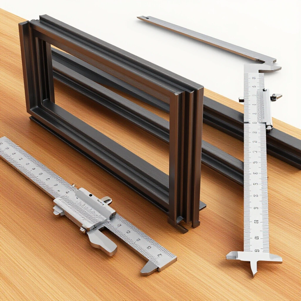
Troubleshooting in a fabrication environment is about more than just finding a broken part. It is a mindset of constant verification. Whether I am hunting down the cause of intermittent tool chatter on a lathe or trying to figure out why a structural frame has developed a subtle twist, the process remains the same. We observe, we isolate variables, and we measure against a known standard. If your foundation—your frame—is out of square, every subsequent step in the build will amplify that error.
I remember a job for an industrial mill where we were building a custom motor mount frame. The machinist complained of excessive vibration and premature bearing failure. After two days of testing the motor and checking for electrical phase unbalance, I went back to the basics. I pulled out a precision square and a calibrated tape. The frame itself was out of parallel by just 1.5 mm. That tiny deviation was forcing the motor shaft into a slight bind, creating a harmonic vibration that felt like a major mechanical failure. This guide is about preventing those “ghost” problems by mastering the art of manual verification.
Establishing a Baseline for Geometry Verification
Accuracy in steel fabrication refers to how closely a finished frame matches the intended design dimensions and angles. It requires a systematic approach to checking lengths, widths, and diagonals to ensure the structure is not leaning or twisted.
When we talk about troubleshooting mechanical systems, we often start with the most complex component. However, in my experience, the root cause is frequently found in the physical structure. Before you dive into diagnosing spindle backlash or checking for shielding gas contamination in your welds, you must confirm the frame is true. A frame that is out of square by more than 2 mm over a 2-meter span can cause mechanical binding in moving parts, leading to what looks like a motor or controller issue.
To maintain control over your workflow, you need to establish a “zero point.” This is a known accurate surface or measurement from which all other checks originate. If you are troubleshooting a machine that is producing inconsistent parts, start by verifying the frame’s parallelism. If the left side of a frame is 1,500 mm and the right side is 1,502 mm, your machine will never track straight, no matter how much you adjust the software.
The Importance of Tolerance Management
Tolerance is the allowable limit of variation in a physical dimension. In custom steel work, staying within a 1 mm to 2 mm window is standard for most industrial applications, though high-precision machinery may require tighter limits.
I once worked on a project where the fabricator ignored a 1.5 mm error on a base frame, thinking they could “pull it in” during final assembly. By the time they reached the top of the structure, that error had compounded to nearly 10 mm. This is what I call “error stacking.” To avoid this, you must treat every measurement as a diagnostic test. If a measurement fails to meet the tolerance, you stop and identify the cause before moving forward.
Tools and Calibration for Diagnostic Checks
Reliable verification requires tools that are regularly checked for accuracy against a known standard. Using a dropped square or a worn tape measure is like trying to diagnose an electrical fault with a multimeter that hasn’t been zeroed.
You cannot troubleshoot a complex fabrication issue with questionable tools. I’ve seen guys spend hours chasing “tool chatter” that was actually just a loose mounting plate they had checked with a bent ruler. Every diagnostic kit should include a high-quality steel tape, a set of machinist squares, and a precision level.
- Steel Tape Measure: Use a 5-meter or 8-meter tape with a locking hook. Ensure the hook isn’t bent, as a 0.5 mm bend can throw off your internal versus external measurements.
- Machinist Squares: These are essential for checking 90-degree junctions. A standard 12-inch square should be accurate to within 0.002 inches over its length.
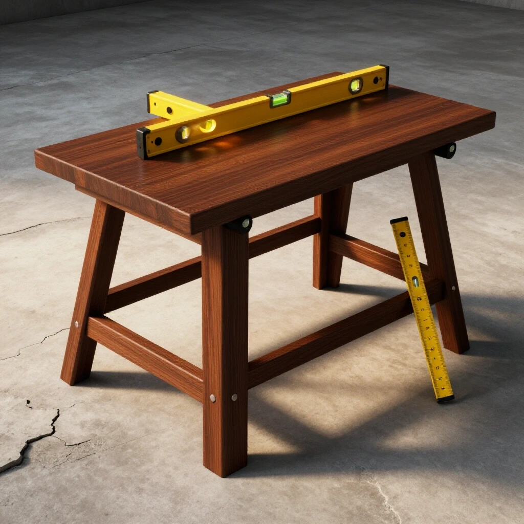
- Spirit Levels: For frames, a level that provides accuracy to 0.5 mm per meter is the baseline for ensuring planarity.
Calibrating Your Measurement Equipment
Calibration is the process of comparing a tool’s reading against a known accurate standard to identify and record any deviation. This ensures that your diagnostic data is consistent and trustworthy throughout the troubleshooting process.
I make it a habit to check my squares against the “flip test.” Place the square against a straight edge, scribe a line, then flip the square over. If the edge doesn’t align perfectly with the line, the square is dead. For tape measures, I check the “hook play.” The hook should move exactly the thickness of the metal hook itself to account for inside and outside measurements. If that movement is jammed with grit or metal shavings, your measurements will be off by at least 1 mm.
| Tool Type | Acceptable Tolerance | Common Failure Mode |
|---|---|---|
| Steel Tape (Class II) | +/- 2.3 mm over 10m | Bent hook or stretched blade |
| Machinist Square | 0.05 mm deviation | Dropped tool or burrs on the edge |
| Precision Level | 0.5 mm per meter | Out of calibration (bubble shift) |
| Digital Caliper | 0.02 mm | Battery low or jaw contamination |
Verifying Linear Dimensions and Parallelism
Linear verification involves checking the distance between two points to ensure they match the design specifications. Parallelism ensures that two opposite members of a frame remain an equal distance apart along their entire length.
In my years of troubleshooting, I’ve found that “parallelism” is often the most overlooked factor in machine failure. If you are dealing with a gantry system that is binding, the first thing I check is the distance between the rails at the front, middle, and back. If you see a variance of more than 0.5 mm, the bearings will fight each other, creating heat and eventual failure.
When measuring long spans, I always use a “pull” tension that is consistent. If you pull a tape tight on one side and leave it slack on the other, you can easily introduce a 2 mm error over a 3-meter span. Consistency is the key to diagnostic accuracy.
Using the Diagonal Check for Squareness
The diagonal check is a method of verifying squareness by measuring from opposite corners of a rectangular frame; if the two diagonal measurements are identical, the frame is square.
This is the most powerful tool in your diagnostic arsenal for frames. If a frame’s diagonals are equal, the corners are 90 degrees. If they differ by even 3 mm, the frame is a parallelogram, not a rectangle. This misalignment is a common root cause for “mysterious” weld defects like cracking, as the internal stresses of the frame are not distributed evenly.
- Measure from the top-left corner to the bottom-right corner.
- Measure from the top-right corner to the bottom-left corner.
- Compare the two values. For a frame under 2 meters, they should be within 1 mm of each other.
Identifying Planarity and Frame Twist
Planarity refers to the condition of a surface where all points lie on a single flat plane. A frame with “twist” has one corner that sits higher or lower than the others, even if the corners are square.
I once spent three days diagnosing a vibration issue on a large industrial fan. We checked the motor, the blades, and the bearings. Finally, I laid a straightedge across the mounting frame. The frame had a twist of 2 mm across the diagonal. When the motor was bolted down, it slightly warped the motor housing, causing the internal components to misalign. This is why checking for a “flat” plane is critical.
The Winding Stick Method
Winding sticks are two identical, straight strips of material placed at opposite ends of a frame to visually amplify any twist or “wind” in the structure. By sighting across the top edges of the sticks, you can see if they are parallel.
If you don’t have a precision laser, winding sticks are incredibly effective. Place one stick at the “head” of the frame and one at the “tail.” Crouch down and sight across the top of the first stick to the second. If the sticks aren’t parallel, your frame has a twist. This simple check can save you from hours of frustration trying to level a machine that is physically warped.
Troubleshooting Common Fabrication Errors
When a frame fails a dimensional check, it is usually due to a specific variable that went uncontrolled. Troubleshooting these errors requires isolating the point in the process where the deviation occurred.
In the same way I look for shielding gas issues when troubleshooting weld porosity, I look for “tack-weld pull” when a frame goes out of square. Welding heat causes metal to expand and contract. If you don’t account for this, the frame will move as you work. Systematic checking after every few tacks allows you to catch these errors before they become permanent.
Diagnostic Pathway for Frame Misalignment
- Check Tool Accuracy: Verify your tape and square are calibrated.
- Measure Diagonals: Identify if the frame is a parallelogram.
- Check Parallelism: Ensure opposite sides are equal lengths.
- Verify Planarity: Look for twists or “high corners.”
- Inspect Joint Fit-up: Look for gaps or overlaps that might have shifted during assembly.
| Symptom | Potential Root Cause | Diagnostic Test |
|---|---|---|
| Diagonals are unequal | Frame is “racked” or leaning | 3-4-5 Triangle check on corners |
| Frame rocks on a flat floor | Twist or winding in the members | Winding stick visual check |
| Opposite sides differ in length | Cutting error or uneven tacking | Direct tape measurement comparison |
| Moving parts bind in the frame | Lack of parallelism | Multi-point width measurements |
Maintaining Mechanical Standards in the Shop
To prevent the need for heavy-duty troubleshooting later, you must maintain a set of shop standards. This includes regular maintenance of your assembly tables and verification tools.
I’ve seen shops where the “flat” assembly table had a 5 mm dip in the center. Every frame built on that table had a built-in curve. You cannot produce square work on an unsquare foundation. Part of your diagnostic routine should include checking your workspace. Use a long straightedge to ensure your table is flat within 1 mm across its entire surface.
Establishing a Verification Checklist
A checklist ensures that no step is skipped in the heat of a project. It turns a complex diagnostic process into a series of simple, repeatable actions.
- Zero the Tape: Ensure the hook is clean and moving correctly.
- Confirm Cut Lengths: Measure all matching components before assembly.
- Square the First Corner: Use a machinist square to set the baseline.
- Tack and Re-check: Measure diagonals immediately after tacking.
- Final Diagonal Sweep: Confirm squareness before final welding.
- Planarity Sight: Use winding sticks to ensure no twist has been introduced.
Advanced Diagnostic Exercises
To sharpen your skills, I recommend practicing “blind” diagnostics. Have a colleague intentionally misalign a small test frame by 2 mm and see how quickly you can identify the exact location and type of error using only manual tools.
In my 18 years of troubleshooting, I’ve found that the best fabricators are the ones who are the most skeptical of their own work. They don’t assume a corner is square because it “looks” right. They prove it is square with data. Whether you are dealing with tool chatter on a mill or a structural frame for a building, the data doesn’t lie.
Case Study: The Vibrating Lathe Bed
I was called to a shop where a high-end lathe was producing poor surface finishes. The operator suspected spindle backlash or a motor controller fault. After checking the spindle and finding it within the 0.002-inch tolerance, I looked at the custom steel stand they had built for the machine.
By measuring the diagonals of the stand’s top plate, I found a 4 mm discrepancy. The stand was twisted, which meant the lathe bed was being pulled into a slight warp when bolted down. We shimmed the lathe to compensate for the frame’s twist, and the “tool chatter” disappeared instantly. The problem wasn’t the machine; it was the frame it sat on.
Summary of Key Metrics for Frame Verification
To ensure your work meets industrial standards and avoids mechanical issues, keep these benchmarks in mind:
- Linear Tolerance: +/- 1.5 mm for general fabrication.
- Diagonal Variance: Less than 2 mm for frames up to 2 meters.
- Parallelism: Within 0.5 mm for machine-grade rails or guides.
- Planarity: No more than 1 mm of twist over a 1-meter span.
- Squareness: 90 degrees within 0.05 degrees for precision setups.
Mastering these simple checks is the foundation of becoming a top-tier diagnostic specialist. When you can trust your frame, you can accurately troubleshoot the more complex mechanical and electrical systems that rely on it.
Frequently Asked Questions
How do I know if my tape measure is accurate enough for machine frames? Check your tape against a high-quality steel rule. If the markings align perfectly over a 300 mm span, it is likely a Class II tape, which is sufficient for most steel frames. Always use the same tape for all measurements on a single project to avoid “inter-tool” variance, which can be as much as 1 mm between different brands.
What is the “3-4-5 rule” and how does it help with troubleshooting? The 3-4-5 rule is based on the Pythagorean theorem (a² + b² = c²). If you measure 300 mm along one side and 400 mm along the adjacent side, the diagonal between those two points must be exactly 500 mm if the corner is square. This is an excellent way to verify large frames where a standard square is too small to be accurate.
Why do my diagonals keep changing after I tack-weld the corners? This is usually due to “weld pull.” As the weld nugget cools, it shrinks and pulls the metal toward the weld. To troubleshoot this, try tacking on the “outside” of the corner first to resist the pull, or use temporary bracing. Always re-measure diagonals after every two or three tacks.
Can a frame be square but still be “twisted”? Yes. A frame can be a perfect rectangle (equal diagonals) but have one corner lifted higher than the others. This is called a “wind” or twist. You must check for planarity using winding sticks or a precision level in addition to checking for squareness.
What is the most common cause of “racked” frames? Racking occurs when the frame becomes a parallelogram. This is almost always caused by an uneven assembly surface or failing to secure the first two corners at a true 90-degree angle. If your assembly table isn’t level, the frame will naturally follow the gravity of the slope during assembly.
How much error is “too much” for a custom steel base? For most industrial applications, any error over 2 mm is problematic. If the frame supports moving parts, like a CNC gantry or a motor, you should aim for less than 0.5 mm of deviation to prevent mechanical binding and vibration.
How do I check for parallelism over a long distance without a laser? Use a “spacer block” or a dedicated gauge rod. Cut a piece of scrap to the exact width required and slide it between the two parallel members at various points. If the block binds or has a gap at any point, the members are not parallel.
What should I do if my diagonals are off by 5 mm on a finished frame? If the frame is only tack-welded, you can often “cold-set” it by using a heavy clamp or a come-along to pull the long diagonal until it matches the short one. However, if it is fully welded, you may need to cut some joints loose. This highlights why checking dimensions during the process is so critical.
Does temperature affect my dimensional checks? Steel expands at a rate of about 0.012 mm per meter per degree Celsius. While this is negligible for small shop projects, if you are measuring a 10-meter frame in a 40-degree shop and comparing it to a blueprint designed at 20 degrees, you could see a difference of over 2 mm. Always try to measure at a consistent temperature.
How can I verify my level is actually level? Place the level on a surface and note the bubble position. Rotate the level 180 degrees (end-for-end). If the bubble is in the exact same position relative to the vial lines, the level is accurate. If it shifts, the level needs calibration or replacement.
(This article was written by one of our staff writers, Paul Whitaker. Visit our Meet the Team page to learn more about the author and their expertise.)