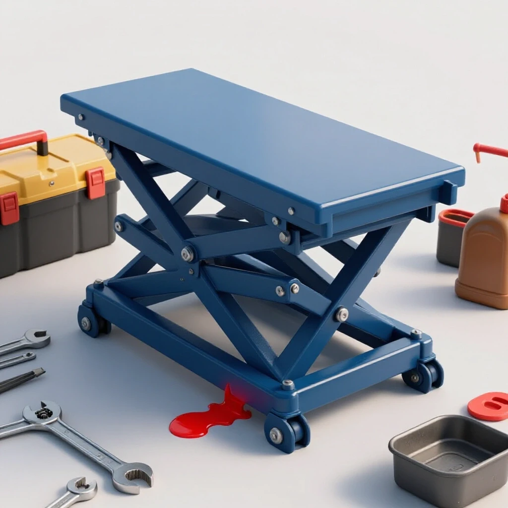
How to Troubleshoot a Leaking Hydraulic Lift Table (DIY Fix)
I have spent the last 15 years in the middle of workshop chaos, often standing over a machine that refuses to behave while a deadline looms. One of the most common, yet frustrating, issues I encounter involves hydraulic lifting equipment that loses its height over time or leaves a telltale puddle on the shop floor. When a piece of equipment fails to hold a load, it is easy to feel overwhelmed by the complexity of fluid power. However, resolving these issues does not require a degree in fluid dynamics; it requires a systematic approach to isolation and repair.
In my experience, whether I am troubleshooting weld porosity in a critical joint or tracking down a vibration in a lathe, the process remains the same. You must observe the symptoms, isolate the variables, and test your theories one at a time. A sinking lift table is no different. It is a closed system that has developed a breach, either internally or externally. My goal is to walk you through the exact steps I use to find those breaches and fix them using basic shop tools. This guide will help you move away from guesswork and toward a methodical repair process that saves time and keeps your equipment in service.
Establishing a Systematic Diagnostic Framework for Fluid Power
A systematic diagnostic framework is a structured method used to identify the root cause of a mechanical failure by narrowing down possibilities through observation and testing. This approach prevents the “parts cannon” method, where a technician replaces components randomly, hoping to stumble upon a solution without understanding the underlying problem.
When I approach a failing hydraulic system, I start with a clean slate. I wipe down every component until the metal is dry. This is because hydraulic oil has a way of traveling along hoses and frames, making it difficult to find the actual point of exit. In the same way a metalworking diagnostic guide helps you identify if a weld defect is caused by gas flow or wire speed, a fluid power framework helps you distinguish between a bad seal and a loose fitting.
I always begin by asking three questions: Is the fluid escaping the system (external)? Is the fluid bypassing a seal inside the system (internal)? Or is there air trapped where fluid should be? By answering these questions first, I can ignore 70% of the machine and focus on the 30% that is actually broken. This saves hours of unnecessary disassembly.
- Observation: Look for wet spots, dust buildup on oily surfaces, and the speed at which the table sinks.
- Isolation: Use clamps or shut-off valves to see if the problem persists when certain sections of the system are blocked off.
- Variable Control: Change only one O-ring or tighten one fitting at a time to confirm which action actually resolved the issue.
Identifying External Fluid Loss in Lift Systems
External fluid loss refers to hydraulic oil escaping the pressurized circuit and appearing on the outside of cylinders, hoses, or valves. This type of failure is usually easy to spot through visual inspection, as it leaves physical evidence like puddles or “weeping” joints that collect shop dust and debris.
I once worked on a custom fabrication table that would drop two inches every hour. The owner was convinced the main cylinder was shot. After a quick wipe-down and a five-minute wait under load, I saw a tiny bead of oil forming at the base of a high-pressure hose fitting. It wasn’t the cylinder at all; it was a vibration-loosened nut. In metal fabrication fixes, we often look for the most expensive problem first, but the simplest one is usually the culprit.
To find these leaks, I use a piece of clean cardboard placed under the lift. By marking the spots where oil drips, I can trace the path upward to the source. Common points of failure include the piston rod seal (where the chrome rod exits the cylinder), the hose connections, and the release valve stem. If you see oil on the chrome rod itself, the wiper seal has likely failed, allowing contaminants in and oil out.
| Leak Location | Likely Cause | Diagnostic Step |
|---|---|---|
| Piston Rod | Worn U-cup or Wiper Seal | Extend rod fully and check for deep scratches or “scoring.” |
| Hose Fitting | Loose nut or cracked flare | Clean with degreaser, then dust with baby powder to see the path. |
| Release Valve | Damaged O-ring on the stem | Check if oil is pooling around the foot pedal or hand lever. |
| Cylinder Body | Pin-hole leak in the weld | Inspect the weld seams of the cylinder for “sweating” oil. |
Diagnosing Internal Bypass and Pressure Loss
Internal bypass occurs when hydraulic fluid moves past a seal inside a component, such as a piston seal or a check valve, without exiting the system. This results in a “phantom” leak where the table sinks under load, but no oil is visible on the floor or the machine’s exterior.
This is perhaps the most frustrating issue for fabricators because you cannot see the problem. It reminds me of troubleshooting tool chatter solutions; you know something is wrong because of the finish on the part, but you have to look at the rigidity of the setup to find the cause. With a lift table, if there is no oil on the floor but the table won’t stay up, the oil is simply flowing back to the reservoir through a path it shouldn’t take.
The most common culprit is the piston seal inside the cylinder. If this seal is worn, oil under pressure on one side of the piston leaks to the non-pressurized side. To test this, I raise the table, safely block it, and disconnect the return line. If oil continues to flow out of the return port while the table is under load, that internal seal is finished. Another possibility is a piece of debris stuck in the check valve, holding it slightly open and allowing pressure to bleed back into the tank.
- The “Creep” Test: Mark the height of the table and leave it overnight with a standard load. A drop of more than 0.25 inches usually indicates an internal bypass.
- Valve Inspection: Remove the release valve and check for tiny metal shavings or “swarf.” Even a piece of grit the size of a grain of salt can prevent a valve from seating.
- Temperature Check: Use an infrared thermometer. Fluid bypassing a seal under high pressure generates heat. A hot spot on a valve or cylinder often points directly to the leak.
Replacing Worn Cylinder Seals and Wipers
Cylinder seals are flexible rings, usually made of nitrile or polyurethane, that prevent oil from passing between the piston and the cylinder wall. The wiper seal is the outermost ring that scrapes dirt off the rod as it retracts, protecting the more delicate high-pressure seals inside.
When I find that a seal has failed, I don’t just replace it; I investigate why it failed. In my mechanical troubleshooting steps, I always look for “secondary damage.” If the seal is torn, I check the chrome rod for burrs or pits. If you install a new seal over a scratched rod, that new seal will fail within a week. It is like trying to fix a lathe alignment checklist issue without checking the bed for wear—you are only treating the symptom.
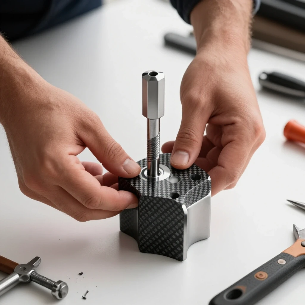
To replace the seals, you must first depressurize the system completely. I then remove the cylinder and use a spanner wrench to unscrew the gland nut. Once the rod is out, I carefully pick out the old U-cups and O-rings using a brass pick. I use brass because it is softer than steel and won’t scratch the seal grooves. If you scratch those grooves, you have created a permanent leak path that no new seal can fill.
- Cleanliness is Critical: Wash all parts in clean solvent and blow them dry with compressed air. A single spec of grit can ruin the repair.
- Lubrication: Coat the new seals in fresh hydraulic oil before installation. Never install a seal “dry,” as the friction of the first stroke can tear the lip.
- Orientation: Note the direction of the “U” in the U-cup seal. The open side of the “U” must always face the high-pressure oil.
- Protection: If the rod has threads on the end, cover them with electrical tape or a thin plastic sleeve before sliding the new seal over them to prevent nicks.
Purging Air and Restoring System Pressure
Purging air, or “bleeding,” is the process of removing trapped gas from the hydraulic lines and cylinders. Because air is compressible and hydraulic fluid is not, trapped air causes “spongy” operation, jerky movements, and a table that may bounce or fail to reach its full height.
Air usually enters the system during a seal replacement or if the fluid level in the reservoir gets too low. It is a common issue that mimics mechanical failure. I have seen guys spend hours on a metalworking diagnostic guide for a “broken” pump when the only problem was a few bubbles in the line. If your lift table feels like it is sitting on a spring rather than a solid column of oil, you have air in the system.
To bleed the system, I start by ensuring the reservoir is full. I then cycle the table up and down several times without a load. On many lift tables, there is a small bleed screw at the top of the cylinder. With the table slightly raised, I crack that screw open just enough to let air hiss out. Once a solid stream of oil appears without bubbles, I tighten it back up. It is a simple fix, but it is the final step in ensuring the repair is successful.
- Full Extension: Raise the table to its maximum height to push air toward the top of the cylinder.
- Fluid Selection: Always use the specific hydraulic oil weight recommended by the manufacturer (usually ISO 32 or 46). Mixing different weights can cause foaming.
- Settling Time: After bleeding, let the machine sit for 30 minutes to allow any tiny micro-bubbles to rise to the top of the reservoir.
Practical Tracking and Maintenance Framework
A maintenance framework is a scheduled set of inspections and data recordings used to track the health of machinery over time. By documenting fluid levels, seal conditions, and table drift rates, a fabricator can predict failures before they cause downtime or safety risks.
I keep a simple logbook for every major piece of equipment in my shop. It doesn’t have to be complicated. I track the date of the last oil change and the “drift rate” of the lift. If I notice the table is sinking 0.100 inches more this month than it did last month, I know a seal is starting to go. This proactive approach is the same one I use for a lathe alignment checklist; catching a 0.002-inch deviation early is much cheaper than fixing a 0.020-inch error later.
| Maintenance Task | Frequency | Metric/Target |
|---|---|---|
| Check Fluid Level | Monthly | Within 0.5 inches of fill line |
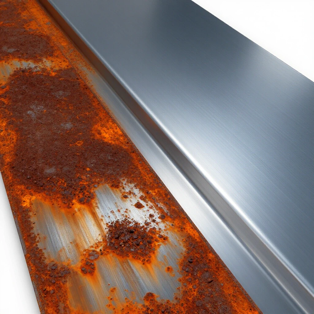
| Inspect Chrome Rod | Weekly | No visible scratches or rust |
| Wipe Down Fittings | Weekly | Metal should be dry to the touch |
| Perform Drift Test | Quarterly | Less than 0.125 inches in 4 hours |
| Change Hydraulic Oil | Annually | Oil should be clear, not milky or dark |
Troubleshooting Common Errors During the Repair Process
Even with a systematic approach, things can go wrong. One of the biggest mistakes I see is over-tightening fittings. In the world of metal fabrication fixes, we often think “tighter is better,” but with hydraulic flares and O-rings, over-tightening can crush the flare or pinch the seal, causing a bigger leak than you started with.
Another common error is ignoring the quality of the hydraulic fluid. If the oil looks milky, it is contaminated with water. If it smells burnt, it has been overheated. Putting bad oil back into a repaired cylinder is like trying to fix troubleshooting weld porosity issues while using contaminated shielding gas—it simply won’t work. Always flush the system if the oil shows signs of degradation.
- Check the Release Valve First: Before tearing down a cylinder, ensure the release lever is fully closing. Sometimes the cable or linkage just needs a 1/16-inch adjustment.
- Use Backup Wrenches: When loosening a hose, always use two wrenches—one to turn the nut and one to hold the fitting body. This prevents twisting and cracking the hard lines.
- Don’t Force the Piston: If the piston doesn’t slide into the cylinder easily, stop. A seal is likely caught. Forcing it will shear the seal lip.
- Verify Load Capacity: Ensure you aren’t troubleshooting a “leak” that is actually just the bypass valve opening because the table is overloaded.
Frequently Asked Questions
Why does my lift table sink slowly even though I don’t see any oil leaking? This is almost always an internal bypass. The oil is leaking past the piston seal inside the cylinder or through a check valve in the pump block. Since the oil stays inside the system and returns to the reservoir, you won’t see a puddle, but the pressure holding the table up is being lost.
Can I use Teflon tape on hydraulic fittings to stop a leak? I strongly advise against using Teflon tape on hydraulic systems. Small shreds of the tape can break off, enter the fluid stream, and clog the tiny orifices in your valves. This can lead to the table failing to lift or failing to lower. Use a dedicated hydraulic thread sealant if necessary, but most hydraulic fittings (like JIC or O-ring boss) are designed to seal without any tape.
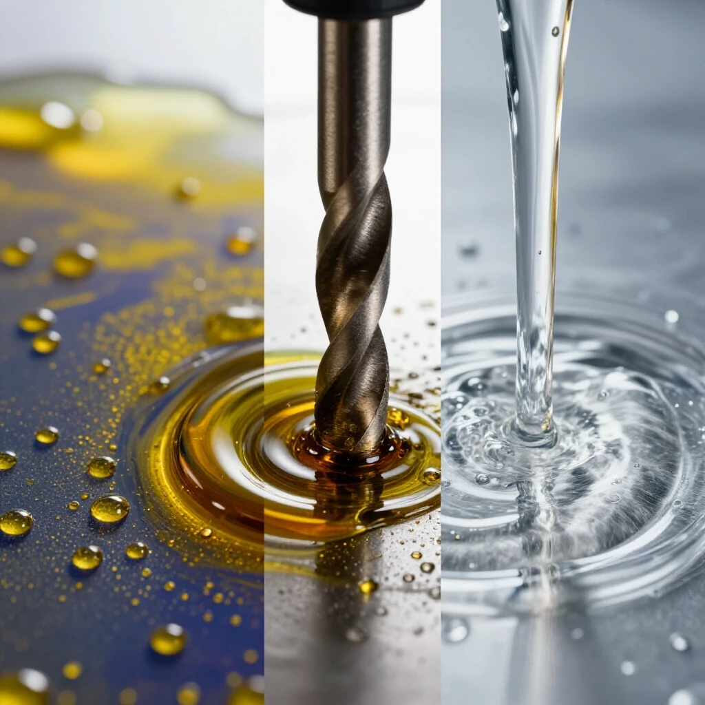
How do I know if my hydraulic oil needs to be changed? Check the color and clarity. Fresh oil is usually a light amber color and completely clear. If it looks “milky” or “cloudy,” it has water in it. If it is dark brown or black and smells like burnt toast, it has been oxidized by heat. In either case, the oil has lost its lubricating properties and should be replaced.
What causes a hydraulic cylinder rod to get “scored” or scratched? Scoring is usually caused by external contaminants like metal chips or grinding dust getting past a worn wiper seal. Once these particles get between the rod and the gland nut, they act like sandpaper. Another cause is “side-loading,” where the load on the table isn’t centered, causing the rod to rub hard against one side of the internal bearings.
Is it possible to repair a scratched cylinder rod? Minor scratches can sometimes be polished out with very fine emery cloth (400-600 grit). However, deep gouges that you can catch with a fingernail will always leak. In those cases, the rod needs to be replaced or professionally re-chromed, as the seal cannot “bridge” a deep gap in the metal.
Why does my lift table jump or shutter when it is going up? This “stiction” or jumping is usually caused by air trapped in the cylinder or a lack of lubrication on the table’s scissor slides. First, try bleeding the air out of the system. If that doesn’t work, grease the rollers and pivot points of the scissor mechanism.
What is the correct way to measure an O-ring for replacement? You need to measure three things: the inside diameter (ID), the outside diameter (OD), and the cross-section (thickness). Use a digital caliper for accuracy. It is also important to know the material; most hydraulic systems use Nitrile (Buna-N), but if the system runs very hot, you may need Viton.
Can I use motor oil in my hydraulic lift table? No. Motor oil contains detergents and additives designed for combustion engines that can cause foaming and seal swelling in hydraulic systems. Always use a dedicated hydraulic oil (ISO 32 or 46 are most common for lift tables) to ensure the pump and seals last.
How tight should I tighten the gland nut on the cylinder? The gland nut should be tight enough to be secure, but it doesn’t need to be “cranked” with an impact wrench. Usually, “snug plus a quarter turn” with a spanner wrench is sufficient. The seal does the work of stopping the oil; the nut just holds the components in place.
What should I do if the table won’t go down at all? Check for mechanical obstructions in the scissor legs first. If the frame is clear, the issue is likely in the release valve. A piece of debris could be blocking the return port, or the valve stem could be bent. Never try to force the table down; instead, slowly loosen the hydraulic hose at the cylinder to carefully bleed off pressure and lower the load.
(This article was written by one of our staff writers, Paul Whitaker. Visit our Meet the Team page to learn more about the author and their expertise.)