How to Replace Worn Spindle Bearings on Drill Press (Fix)
I’ve spent the last 15 years in fabrication shops where the machines are often older than the operators. There is a specific kind of frustration that sets in when a trusted piece of equipment starts producing sub-par work. You’re halfway through a precision bracket, and suddenly, the drill bit is walking across the workpiece or the finish looks like a plowed field. In my experience, these issues aren’t usually a sign that the machine is scrap. Instead, they are often a signal that the internal rotating components have reached their limit.
Early in my career, I spent three days chasing a “weld porosity” issue on a heavy-duty baseplate. I checked the gas flow, the wire speed, and even the base metal chemistry. It turned out the vibration from a nearby drill press was so severe it was literally shaking the shielding gas away from the arc. The culprit was a set of collapsed bearings in the drill spindle. That lesson stuck with me: mechanical stability is the foundation of every other process in the shop. If your primary rotation point is compromised, your accuracy, tool life, and even your weld quality will suffer.
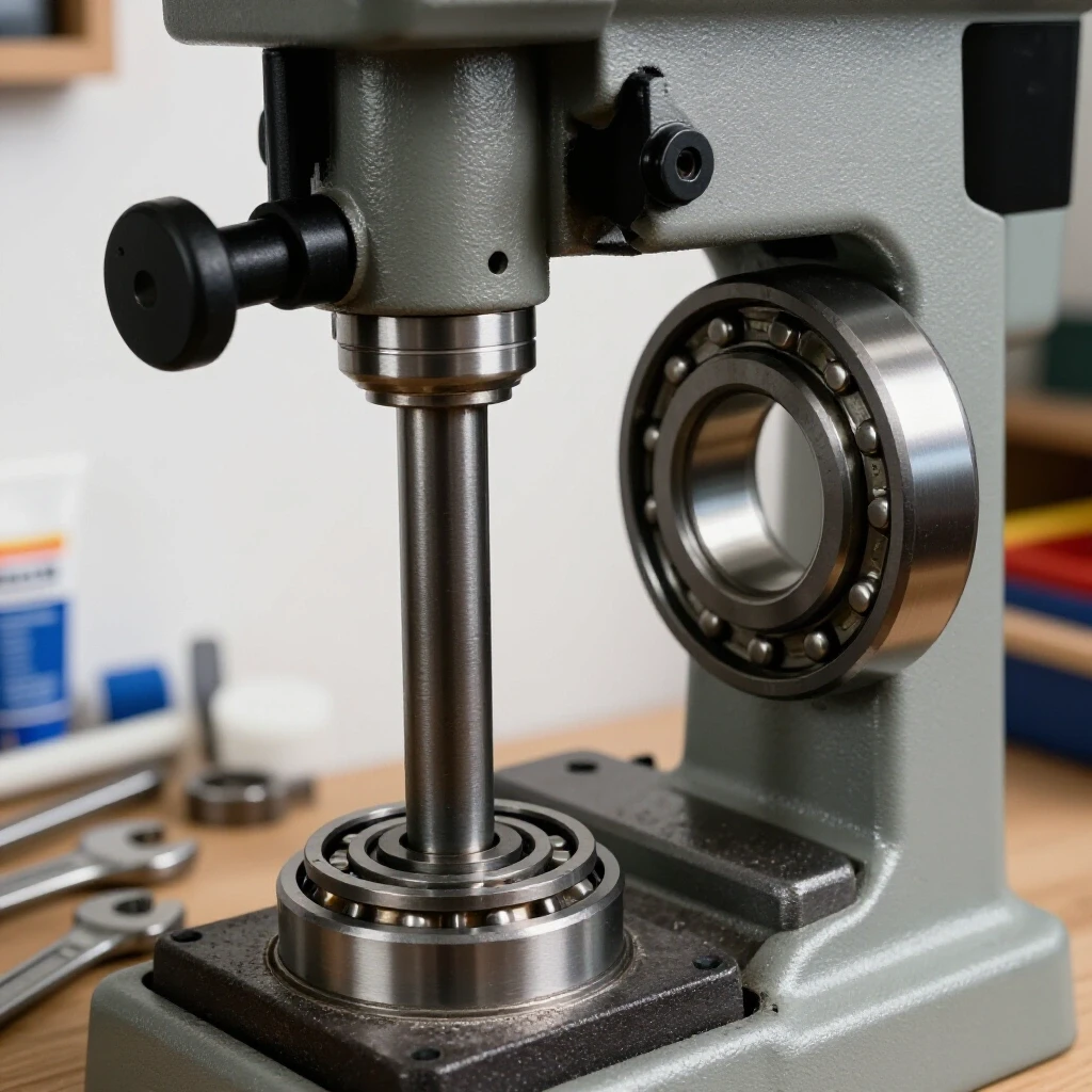
Mastering the process of restoring mechanical integrity to your boring equipment requires a systematic approach. We aren’t just swapping parts; we are diagnosing a system of tolerances. By isolating variables and following a structured path, you can bring a vibrating, noisy machine back to factory specifications.
Identifying the Signs of Spindle Component Failure
Identifying the signs of failure involves observing physical deviations and audible cues that indicate the internal rolling elements are no longer maintaining a true axis of rotation. This phase is about separating normal operational wear from critical mechanical breakdown.
When a machine starts to fail, it rarely happens all at once. It begins with a subtle change in the “harmonics”—the sound the machine makes under load. You might notice a high-pitched whine or a low-frequency rumble. If you feel a rhythmic thumping through the feed handle, you are likely feeling “spalling,” which occurs when the hardened surface of a bearing race begins to flake off.
Another major red flag is tool chatter. In metalworking, chatter is a resonant vibration that creates a wavy pattern on the surface of the metal. While chatter can be caused by incorrect speeds and feeds, a worn-out rotating assembly will make it impossible to eliminate. If you’ve adjusted your RPM and feed rate but the vibration remains, the mechanical seat of the tool is likely the problem.
Common Symptoms of Mechanical Instability
| Symptom | Probable Root Cause | Diagnostic Test |
|---|---|---|
| Excessive Radial Play | Worn spindle or quill bearings | Side-to-side movement check with dial indicator |
| High-Frequency Screech | Lack of lubrication or “brinelling” | Temperature check with infrared thermometer |
| Oval-Shaped Holes | Spindle runout or axial slop | Bore measurement with telescoping gauges |
| Rapid Tool Blunting | Micro-vibrations chipping the cutting edge | Visual inspection under magnification |
Diagnostic Frameworks for Mechanical Stability
Diagnostic frameworks are structured methods used to isolate specific mechanical faults by measuring deviations from a known baseline, such as factory-spec runout or axial play. These steps ensure you aren’t replacing parts that are still functional.
Before you pull the machine apart, you need data. I start by measuring “runout.” Runout is the degree to which a shaft rotates off its center axis. To test this, I use a dial indicator with a magnetic base. Attach the base to the machine table and place the indicator tip against the inside of the spindle taper or the outside of the spindle nose.
Slowly rotate the spindle by hand. For most standard shop equipment, a runout of 0.001 to 0.005 inches is acceptable. If you see the needle jumping more than 0.007 inches, the internal support is gone. You also need to check for “axial play,” which is movement up and down. Push and pull the spindle vertically; any perceptible “clunk” indicates that the pre-load on the bearings has failed.
Isolating the Quill from the Spindle
It is easy to mistake a loose “quill”—the sleeve that moves up and down—for a bad spindle. To isolate these, I lock the quill at mid-travel. If the whole sleeve moves, you may just need to tighten the quill pinch bolt on the head casting. If the sleeve is rock solid but the spindle inside it wobbles, you have confirmed that the internal rolling elements are the issue.
- Check runout at the spindle nose, not the chuck.
- Measure temperature after 10 minutes of dry running; anything over 140°F is a sign of friction.
- Listen for “skidding” sounds, which suggest the rollers are sliding rather than rolling.
The Disassembly Sequence for Vertical Boring Equipment
The disassembly sequence is a step-by-step mechanical teardown designed to access internal rotating parts without damaging the precision-machined housings or the return spring mechanism. Proper sequencing prevents the “spring-loaded surprises” common in shop repairs.
The most dangerous part of this job is the clock spring that returns the handle. I’ve seen guys lose a fingernail because they didn’t respect the stored energy in that housing. Before you touch the spindle, you must carefully unwind the spring tension. I usually use a pair of locking pliers to hold the housing while I back off the retaining nuts.
Once the tension is off, the quill assembly usually slides out the bottom of the head. You may need to remove a stop-bolt or a woodruff key first. I always lay a piece of heavy rubber or a thick rag on the table to catch the assembly. These components are precision-ground; dropping them on a cast-iron table can create a burr that will ruin the fit forever.
Removing the Internal Shaft
With the quill on the bench, you’ll see the spindle shaft trapped inside. Usually, there is a threaded collar or a snap ring holding it in. I prefer using a dedicated snap-ring plier set rather than trying to “make do” with screwdrivers. Once the retainers are off, the spindle can be pressed out.
I rarely use a hammer here. A hammer creates “shock loading” which can mar the internal surfaces. Instead, I use a small arbor press or even a heavy-duty bench vise with a large socket to act as a receiver. You want a steady, even pressure of about 50 to 100 psi to move the shaft through the interference fit.
Selecting and Preparing High-Precision Replacement Components
Selecting replacement components involves choosing the correct bearing grade, seal type, and load rating to match the machine’s intended RPM and material demands. This stage ensures the repair lasts longer than the original factory parts.
Most drill presses use standard metric ball bearings, often in the 6200 series (like a 6203 or 6204). However, the “suffix” on the part number matters more than most people realize. A “2RS” suffix means the bearing has two rubber seals, which is excellent for keeping metal dust out. A “ZZ” suffix means metal shields, which are better for high-speed heat dissipation but less effective against fine grinding dust.
In a metal fabrication environment, I almost always go with the 2RS (rubber sealed) option. The fine dust from grinding and welding can act like lapping compound if it gets into the grease. I also look for a “C3” clearance rating. This means the bearing has a bit more internal room to allow for thermal expansion when the machine gets hot during a long production run.
Bearing Grade Comparison
| Feature | Shielded (ZZ) | Sealed (2RS) | Open (No Suffix) |
|---|---|---|---|
| Dust Resistance | Moderate | High | None |
| Max RPM | High | Moderate | Very High |
| Maintenance | Maintenance-Free | Maintenance-Free | Requires Oil Bath |
| Best Use | High-speed wood | Metal fabrication | Industrial gearboxes |
Reassembly and Tolerance Verification
Reassembly is the process of seating new components into their housings using thermal or mechanical force, followed by a final calibration check to ensure the machine meets operational standards. This is where you verify that your “fix” actually solved the root cause.
Before I install the new bearings, I put the spindle shaft in the freezer for an hour and gently warm the quill housing with a heat gun (not a torch). This creates a “thermal fit.” The cold shaft shrinks slightly, and the warm housing expands. Often, the parts will slide together with almost no force. If you must use a press, only apply pressure to the “race” that is being fitted. If you are pressing a bearing onto a shaft, push on the inner race. If you are pressing it into a hole, push on the outer race.
Never apply force across the rolling elements. If you do, you’ll create tiny dents called “brinelling,” and the bearing will be noisy from day one. Once everything is seated, I re-apply the dial indicator. I’m looking for a “total indicated runout” (TIR) of less than 0.002 inches.
Final Calibration Steps
- Re-tension the return spring just enough to lift the quill; over-tightening causes premature wear.
- Apply a light coat of machine oil to the outside of the quill to prevent “stiction.”
- Run the machine at its lowest RPM for 5 minutes to distribute the internal grease.
- Check for heat; the housing should be warm to the touch (approx 100°F) but not hot.
Case Study: The Mystery of the Oval Hole
A few years ago, I was working with a fabricator who was struggling with a series of structural baseplates. Every time he drilled a 0.750-inch hole, the bolt wouldn’t fit. We measured the holes, and they were 0.765 inches in one direction and 0.748 inches in the other. He thought it was a bad batch of drill bits or a “walking” issue caused by poor center-punching.
I set up my diagnostic gear and found that his spindle had 0.012 inches of radial play. As the drill bit entered the steel, the resistance caused the spindle to deflect. Because the bearings were worn unevenly, the spindle “orbited” rather than rotated. We spent two hours replacing the bearings with high-quality ABEC-3 rated units.
The result was immediate. The chatter vanished, and the holes became perfectly round within 0.002 inches. This saved him from scrapping $1,200 worth of material. It’s a prime example of how mechanical troubleshooting can solve what looks like a “material” or “tooling” problem.
Actionable Tracking Frameworks and Maintenance Logs
A systematic approach requires documentation. If you don’t track the health of your machines, you’re always in “reactive” mode. I recommend keeping a simple logbook for every major tool in the shop. This allows you to spot trends before they become failures.
- Initial Baseline: Record the runout and noise level when the machine is “healthy.”
- Vibration Log: Every six months, use a smartphone-based vibration analyzer to check the “G-force” levels at the headstock.
- Lubrication Schedule: Note the type of grease used. Mixing lithium-based grease with polyurea-based grease can cause the lubricant to harden and fail.
- Tool Life Tracking: If you notice you’re sharpening bits twice as often, it’s time to check the spindle.
Tool Calibration Checklist
- Verify Table Squareness: Use a precision square to ensure the table is 90 degrees to the spindle.
- Check Belt Tension: Over-tight belts pull the spindle to one side, wearing out the top bearing prematurely.
- Inspect the Taper: Look for “tang damage” or galling inside the spindle; use a taper reamer to clean up minor burrs.
- Test the Quill Lock: Ensure the lock doesn’t shift the spindle alignment when engaged.
Conclusion: Restoring the Heart of the Shop
Maintaining the mechanical integrity of your shop equipment is a continuous process of observation and correction. When you take the time to replace worn internal components, you aren’t just fixing a drill; you are ensuring that every weld, every bolt hole, and every assembly that follows is built on a stable foundation.
The process requires patience and the right tools—a dial indicator, a snap-ring plier set, and perhaps a small press. But the payoff is a machine that works with you rather than against you. By following these systematic steps, you can eliminate the “electrical gremlins” and “vibrational ghosts” that haunt so many fabrication shops, allowing you to focus on the craft of building.
FAQ: Frequently Asked Questions
How can I tell if the vibration is from the motor or the spindle? The easiest way to isolate the source is to remove the drive belt. Turn the motor on by itself. If the vibration is still there, the motor bearings or the pulley balance are the problem. If the motor is smooth, turn the spindle by hand. If you feel any “grittiness” or resistance, the fault lies within the spindle assembly.
What is “spindle runout” and why does it matter for welding? Spindle runout is the amount a tool wobbles as it spins. In fabrication, high runout creates oversized holes and poor surface finishes. This matters for welding because poorly fitted parts require larger weld beads to fill gaps, which increases “heat input” and leads to material warping and potential weld porosity.
Do I need a hydraulic press to replace these components? Not necessarily. While a 10-ton hydraulic press makes the job easier, many shop-grade machines have “light interference fits.” You can often use a large bench vise or even a length of threaded rod with heavy washers and nuts to create a “puller” that seats the parts smoothly.
Why did my new bearings fail after only a month of use? The most common cause of early failure is “installation damage.” If you hit the bearing with a hammer or pressed it in by the wrong race, you likely created flat spots on the balls. Another cause is “over-tensioning” the drive belts, which puts a constant sideways load on the bearings that they aren’t designed to handle.
Is it worth buying expensive high-precision bearings? For a standard drill press, you don’t need “super-precision” (ABEC-7 or 9) bearings. However, avoid the cheapest “unbranded” options. Stick with reputable brands like SKF, FAG, or NSK. An ABEC-3 or ABEC-5 rating is the “sweet spot” for metalworking, offering a great balance of accuracy and durability.
Can I just “re-grease” old bearings to save money? If a bearing is making noise or has “play,” the metal surfaces are already damaged. Adding grease might quiet the noise for an hour, but it won’t fix the physical wear. In a professional shop environment, the labor time to pull the machine apart is much more expensive than the parts; always replace them with new units.
What is “backlash” in a drill press spindle? Backlash usually refers to the “slop” in the rack-and-pinion gears that move the quill up and down. While it doesn’t affect the roundness of the hole, it can cause the drill to “grab” and pull itself into the work as it breaks through the bottom. This can be minimized by adjusting the quill return spring or the tension bolt.
How does spindle heat affect my fabrication tolerances? As the spindle heats up, the metal expands. This can change the length of the spindle by several thousandths of an inch. If you are doing high-precision boring, let the machine run for 10 minutes to reach “thermal equilibrium” before you take your final measurements.
What tools do I need for a systematic diagnostic check? At a minimum, you need a 0.001-inch dial indicator, a magnetic base, a set of telescoping gauges, and an infrared thermometer. For more advanced troubleshooting, a smartphone app that measures vibration frequency can help you identify exactly which part of the machine is out of balance.
Can worn bearings cause my drill bits to break? Yes. When the spindle wobbles, it puts “side-load” on the drill bit. Drill bits are designed for axial compression (pushing down), but they are brittle and have very little resistance to bending. A wobbly spindle will snap small bits and cause “chipping” on the corners of larger bits.
(This article was written by one of our staff writers, Paul Whitaker. Visit our Meet the Team page to learn more about the author and their expertise.)