How to Build a Strong Steel Canopy Frame for Outdoors (Tips)
I remember the first time I tried to build a large overhead structure for my backyard workspace. I had measured every piece of square tubing to the sixteenth of an inch. My cuts were clean, and my floor was relatively level. But as soon as I finished running the final beads on the main rafters, I noticed a problem. The far corner of the frame had lifted three inches off the ground. The heat from my welder had turned a flat assembly into a giant, steel potato chip. That was twelve years ago, and it taught me that in custom fabrication projects, the metal is alive. If you don’t understand how it moves when it gets hot, it will fight you every step of the way.
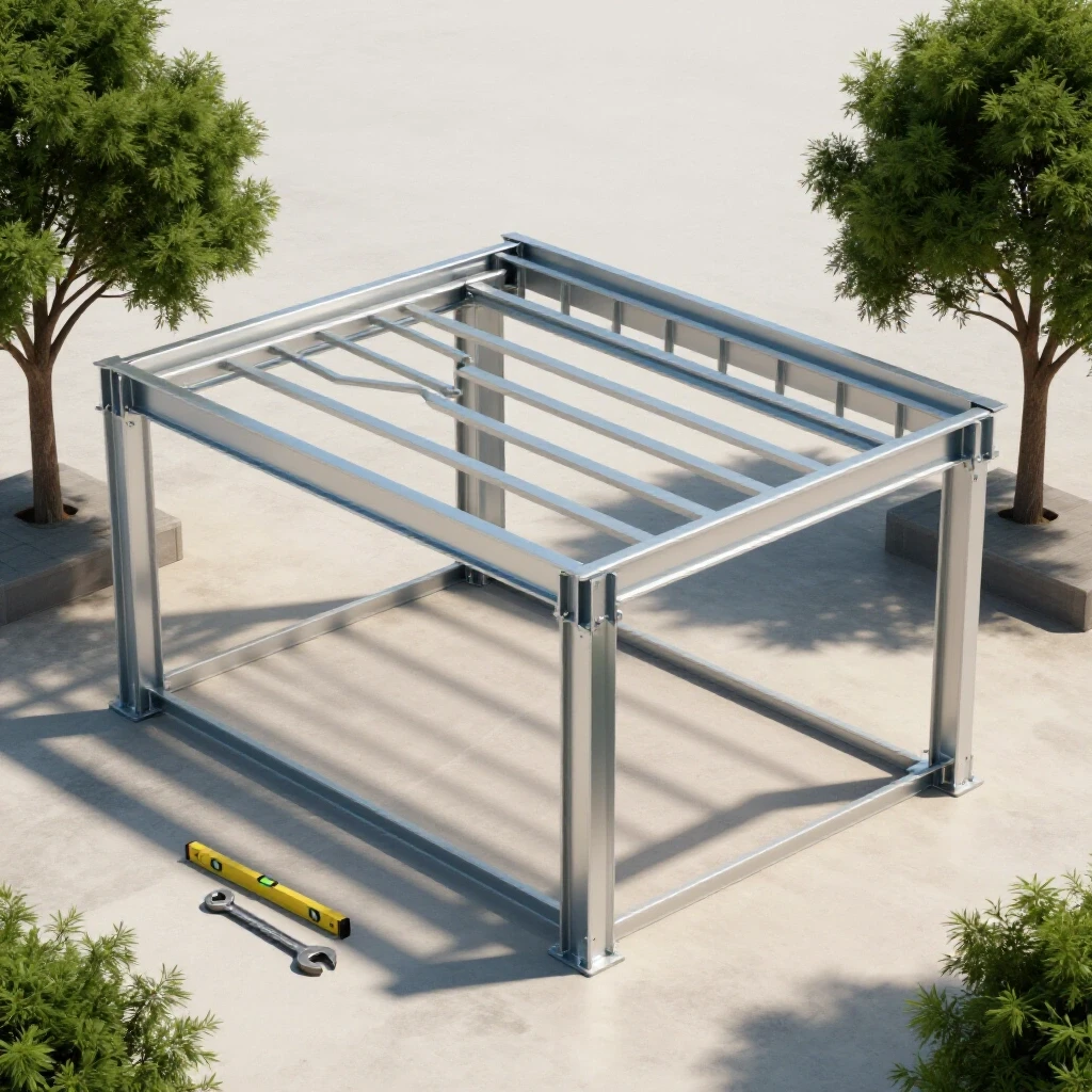
As a former prototype technician, I’ve spent thousands of hours learning that a successful build isn’t just about a steady hand with a MIG torch. It is about the preparation you do before the hood even drops. Whether you are building a utility trailer or a heavy-duty outdoor frame, you have to account for material shrinkage, blade thickness, and the physical forces of cooling steel. This guide is a breakdown of how I approach these builds now to ensure they stay square, flat, and structurally sound.
Mastering the Layout: Planning for Kerf and Material Loss
Layout planning is the process of translating a 2D design into a physical cut list while accounting for the physical space a saw blade occupies. It ensures that your final assembly matches your intended dimensions without running short on material.
Before I ever touch a saw, I create a detailed cut list. One of the biggest mistakes I see in workshop projects is forgetting about the “kerf.” The kerf is the width of the material removed by the cutting tool. If you are using a standard abrasive chop saw, that blade might be 1/8 of an inch thick. If you make ten cuts on a single stick of steel, you’ve lost over an inch of material. On a large frame, that loss can make your horizontal spans too short to reach the vertical posts.
I always calculate my cuts based on the “outside-to-outside” dimensions. If I need a frame that is exactly 120 inches wide, and I’m using 2-inch square tubing, I have to decide if my rafters sit on top of the posts or between them. This choice changes every measurement in the list. I also use a layout software or even a simple graph paper sketch to visualize the joints. This helps me identify where I need 45-degree miters versus simple 90-degree butt joints.
Metal Kerf Allowances by Cutter Type
| Cutting Tool Type | Typical Kerf Width (Inches) | Precision Level | Best Use Case |
|---|---|---|---|
| Abrasive Chop Saw | 0.125″ – 0.150″ | Low | Rough framing, thick beams |
| Cold Saw | 0.080″ – 0.100″ | High | Precision miters, clean finishes |
| Horizontal Bandsaw | 0.035″ – 0.050″ | Medium | Repeatable production cuts |
| Plasma Cutter (Handheld) | 0.060″ – 0.090″ | Low | Irregular shapes, thick plate |
| Laser/Waterjet | 0.005″ – 0.015″ | Extreme | Complex brackets, tight tolerances |
Key Takeaway: Always mark your cut line and then place the blade on the “waste” side of the line. This preserves your actual measurement and keeps your frame components consistent.
Building Workshop Jigs and Fixtures for Alignment
Workshop jigs and fixtures are temporary or permanent tools used to hold workpieces in a fixed position during the assembly process. They act as a “third hand” to maintain squareness and prevent parts from shifting under the pressure of clamps or heat.
You cannot rely on magnets alone to hold a heavy frame square. Magnets are great for a quick tack, but they are easily bumped and offer zero resistance to the pulling forces of a cooling weld. When I’m working on a large outdoor structure, I often build a temporary fixture right on my welding table or even on a flat concrete floor using scrap angle iron.
I use “stops” and “cleats.” These are small blocks of steel tacked down to a flat surface that the frame pieces can butt up against. By creating a corner jig that is verified square with a 3-4-5 triangle calculation, I can drop my tubing into the jig and know it is aligned. This setup is essential for metal layout tips because it allows you to repeat the same alignment for multiple corners without re-measuring every time.
- Use heavy-duty C-clamps or F-clamps to pull the steel tight against your jigs.
- Check for “twist” by sighting across the top of the tubes; they should look like a single line.
- Verify squareness by measuring the diagonals of the frame; they must be equal within 1/16th of an inch.
- Leave a small gap (about 1/16″) at the joints for better weld penetration, known as a “root opening.”
The Science of Tack Welding and Structural Integrity
Tack welding involves placing small, temporary welds at key points to hold an assembly together before the final welding begins. These tacks must be strong enough to resist the initial heat pull but small enough to be easily ground away if an error is found.
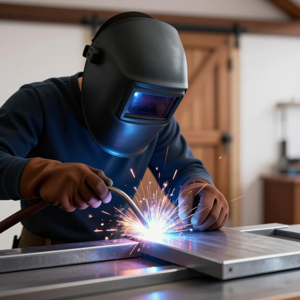
I’ve seen many builders put a tiny, weak tack on one corner and then wonder why the frame pulled out of square by a half-inch. When you are working on a large custom fabrication project, your tacks need to be strategic. I use what I call “bridge tacks.” Instead of just a dot of metal, I make sure the tack penetrates both pieces of steel.
For a standard 2-inch square tube, I place at least four tacks—one in the center of each side. I start by tacking the “inside” corners first. As the weld cools, it will naturally want to pull the joint tight. If you tack the outside first, the cooling metal can actually open up the gap on the inside, making your final bead much harder to run.
Standard Tack Weld Spacing and Sizing
- Tack Size: Generally 2 to 3 times the thickness of the base metal in length.
- Tack Strength: For 1/8″ wall tubing, a 1/4″ long tack is usually sufficient.
- Spacing for Long Runs: Place a tack every 8 to 12 inches to prevent the plates from “zippering” or bowing apart.
- Alignment Check: Always re-measure your diagonals after tacking but before final welding. This is your last chance to fix a mistake with a simple cut of a grinder.
Why Weld Shrinkage Warps Square Structures
Weld shrinkage occurs because steel expands when heated and contracts as it cools. Because the weld bead is liquid and then solidifies, it pulls the surrounding base metal toward the center of the weld, creating angular distortion.
Understanding angular pull is the difference between a straight frame and a twisted mess. Imagine a T-joint. If you weld only one side of that joint, the cooling weld metal will act like a shrinking rubber band, pulling the vertical post toward the side you just welded. To combat this, you have to use a specific weld sequencing layout.
In my years as a prototype tech, I learned that you never finish one joint completely before moving to the next. You have to distribute the heat. If you dump all the heat into the front-left corner of a canopy frame, that corner will contract more than the others, causing the entire structure to “diamond” or rack out of square.
Weld Sequencing and Distortion Control
| Sequence Strategy | How It Works | Best Application |
|---|---|---|
| Back-Stepping | Welding in short sections in the opposite direction of the overall travel. | Long seams on plate or large beams. |
| Opposing Sides | Welding side A, then flipping the part to weld side B immediately. | T-joints and I-beam construction. |
| Wandering Sequence | Moving from corner to corner in a star pattern (like lug nuts). | Large rectangular frames and chassis. |
| Intermittent Welding | Using “stitch” welds instead of one continuous bead. | Non-structural panels or decorative frames. |
Executing the Weld Sequence to Maintain Squareness
Executing a weld sequence is the disciplined practice of jumping between different areas of a project to balance the thermal stresses. This method prevents any single area from becoming too hot and pulling the structure out of alignment.
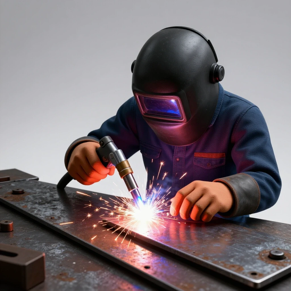
When I start the final welding on a rectangular overhead frame, I follow a “cross-pattern.” I’ll weld the outside of the top-left corner, then move immediately to the outside of the bottom-right corner. By the time I move back to the first corner to do the inside weld, the metal has had a chance to dissipate some heat.
I also pay close attention to the “pull” of the weld. If I notice a corner is starting to pull inward, I will weld the opposite side of that joint next. The second weld will pull the metal back in the other direction, effectively neutralizing the distortion. It is a constant game of tug-of-war where you are the referee.
- Weld the “neutral axis” first: If possible, weld the center of the joint where it is least likely to cause a pivot.
- Balance your beads: If you put a 2-inch bead on the left, put a 2-inch bead on the right.
- Use heat sinks: Clamping a thick piece of copper or scrap aluminum near the weld zone can help suck away excess heat.
- Let it cool: Never rush. If the steel is glowing red over a large area, stop and let it return to room temperature.
Correcting Heat Distortion and Final Straightening
Post-weld correction is the process of using mechanical force or controlled heat to bring a warped structure back into its intended shape. While it’s best to avoid warping, knowing how to fix it is a vital skill for any fabricator.
Even with the best metal warping solutions, some movement is inevitable. If I find a rail has bowed slightly, I use “flame straightening” or mechanical leverage. Mechanical straightening involves using a heavy-duty jack or a winch to pull the metal back into place while it is cold. This works well for minor bows in long spans of tubing.
Flame straightening is more advanced. By heating a small, wedge-shaped area on the “outside” of a curve, you cause that specific spot to expand. Because the surrounding cold metal resists that expansion, the heated spot “upsets” or thickens. When you cool it quickly with water or air, that spot shrinks more than it originally expanded, pulling the beam straight.
- Cold Straightening: Use a hydraulic bottle jack and a heavy chain to “over-bend” the piece slightly past straight; it will usually spring back to the correct position.
- Heat Shrinking: Only heat the metal to a dull cherry red (about 1200°F). Overheating can crystallize the steel and make it brittle.
- Peening: Sometimes, hitting a cooling weld bead with a slag hammer can help relieve the internal tension and reduce the pull.
Final Assembly and Structural Verification
The final stage of the build involves a comprehensive check of all joints, ensuring that every weld is sound and the dimensions meet the original design requirements. This is where you verify the structural integrity of the frame before it is put into service.
Once the frame is cool, I go over every inch with a square and a tape measure. I look for any missed tacks or cold-lapped welds (where the weld sits on top of the metal instead of melting into it). For an outdoor structure that has to withstand wind or snow loads, weld penetration is non-negotiable.
I also check the “flatness” of the mounting points. If this frame is going to be bolted to concrete piers or a wall, the base plates need to be on the same plane. If one is tilted, it will put a constant “preload” stress on the entire frame once it’s bolted down. I use a long straightedge or a laser level to ensure the feet are aligned.
- Grind flush only where necessary: Removing too much weld material can weaken the joint. Only grind for aesthetics or where another part needs to sit flush.
- Check for “undercut”: This is a groove melted into the base metal next to the weld. It acts as a stress riser and can lead to cracks.
- Log your results: I keep a notebook of how much each frame pulled. This data helps me adjust my next build. For example, if I know a certain joint always pulls 1/8 inch, I might “pre-set” it 1/8 inch in the opposite direction next time.
Practical Framework for a Square Build
To keep your project on track, follow this repeatable framework. It helps manage the complexity of custom fabrication and reduces the anxiety of things going wrong.
- The 1/16th Rule: Aim for a dimensional tolerance of +/- 1/16th of an inch. Anything more is usually visible to the eye; anything less is often overkill for outdoor utility projects.
- The Diagonal Check: Always measure from corner to corner. If the two measurements are the same, your frame is square.
- The Clamp Count: You can almost never have too many clamps. If a part can move, it will move.
- The Heat Touch Test: If you can’t keep your hand on the steel six inches away from the weld after a few minutes, you are moving too fast and putting too much heat into the structure.
Building a durable, straight steel frame is a rewarding challenge. It requires a mix of math, physics, and a bit of “feel” for the material. By respecting the way steel reacts to heat and using solid workshop jigs and fixtures, you can build structures that look professional and last for decades.
Frequently Asked Questions
Why does my frame always “diamond” even after I measure it square?
This usually happens because of uneven weld sequencing. If you weld all the joints on one side of a rectangle first, those welds shrink and pull that side shorter, turning your rectangle into a parallelogram. You must jump between opposite corners to balance the shrinkage.
Should I miter my corners at 45 degrees or use butt joints?
Mitered corners look cleaner and provide more surface area for the weld, but they are harder to cut accurately. Butt joints with “end caps” are often stronger for beginners because they are easier to square up and clamp.
How big should my root gap be between two pieces of steel?
For most 1/8″ to 3/16″ wall tubing, a gap of about 1/16″ (the thickness of a welding rod or a thin zip-disc) is ideal. This allows the weld to penetrate all the way through the wall thickness rather than just sitting on the surface.
Can I use a level to square my frame?
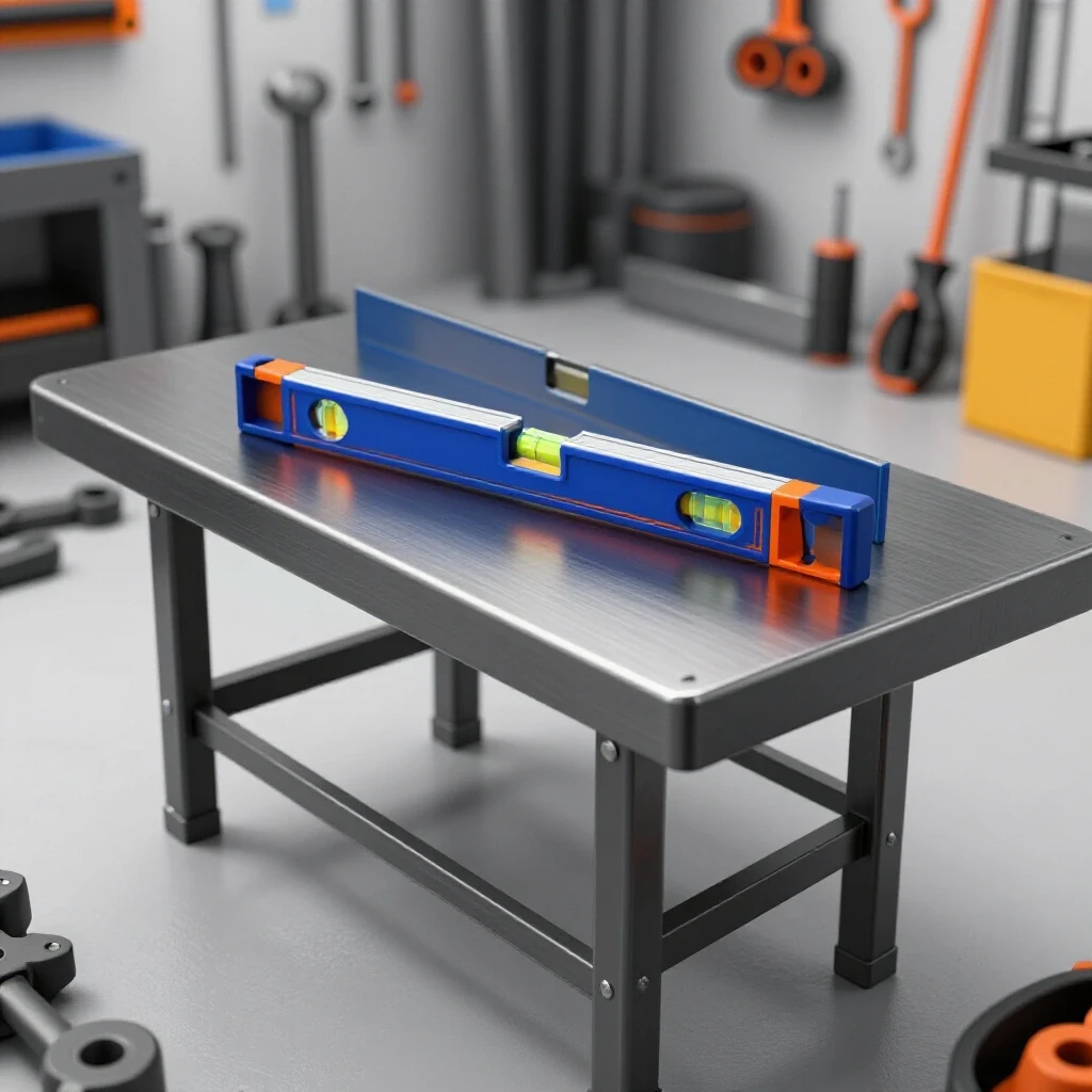
A level only tells you if something is horizontal or vertical relative to the earth. It does not tell you if two pieces of steel are at a 90-degree angle to each other. Always use a framing square or diagonal measurements for true squareness.
Why do my tack welds keep snapping?
If your tacks are snapping, they are either too small or you have too much tension in the metal. Make sure the surfaces are clean of mill scale, and increase the heat slightly on your tacks to ensure they actually fuse the two pieces together.
How do I stop the thin-wall tubing from burning through?
Use a “stitch” technique or lower your wire speed/voltage. You can also aim the arc more toward the thicker part of the joint or a previously laid tack to help dissipate the heat.
Is it better to MIG or Stick weld a canopy frame?
MIG is generally faster and easier for thin-wall tubing (under 1/4″), while Stick is better if you are working outdoors in the wind or on very thick, heavy plate. For most garage-based canopy projects, MIG is the standard choice.
How do I account for the thickness of the paint or powder coating?
If your frame has to fit into a tight space, remember that a good powder coat can add 0.005″ to 0.010″ to every surface. On a large assembly, this can add up to 1/16″ or more. Build your tolerances with a little bit of “breathing room.”
What is the best way to clean mill scale before welding?
Use a flap disc (60 or 80 grit) on an angle grinder. You only need to clean the area where the weld will actually sit—about one inch back from the joint. Removing the grey mill scale ensures a much stronger, cleaner weld.
How do I know if my weld has good penetration?
On square tubing, you can often look inside the tube (before capping it) to see a small “heat tint” or a slight bead of metal protruding through the inside wall. This indicates the weld has traveled through the entire thickness of the steel.
(This article was written by one of our staff writers, Robert Kline. Visit our Meet the Team page to learn more about the author and their expertise.)