How to Build a Mobile Plasma Cutter Hose Storage Cart (Fix)
I remember the first time I tried to build a heavy-duty shop cart. I had spent three hours meticulously measuring every piece of 1.5-inch square tubing. My cuts were clean, and my floor was level—or so I thought. By the time I finished welding the base frame, one corner was lifting nearly half an inch off the ground. I had a “potato chip” frame, a common heartbreak for anyone in custom fabrication projects. That project taught me that steel isn’t a static material; it is a living, breathing thing that moves when you apply heat.
After 13 years as a prototype technician, I have learned that the difference between a professional-grade build and a wobbly mess isn’t just the tools you own. It is how you manage the physics of the build. Whether you are building a rolling stand for your equipment or a dedicated station for organizing heavy leads and hoses, the challenges remain the same. You have to fight the natural tendency of metal to warp, pull, and twist. This guide focuses on the structural reality of building a mobile frame that stays square and true from the first cut to the final coat of paint.
Precision Planning and Material Preparation
Planning is the process of creating a detailed roadmap for your build, including a cut list that accounts for the thickness of your saw blade. Before you strike an arc, you must understand exactly how much material you need and how those pieces will intersect.
In my workshop, I start every project with a “cut list calculator.” This isn’t fancy software; it is a simple ledger where I account for the kerf. Kerf is the width of the material removed by the cutting tool. If you use an abrasive chop saw, your kerf might be 1/8 of an inch. If you use a cold saw or a bandsaw, it might be 1/16 of an inch. If you ignore this, a frame with four joints can end up 1/2 inch shorter than intended.
Calculating Kerf and Material Allowances
- Abrasive Saws: 0.125 inch (1/8″) kerf allowance.
- Bandsaws: 0.045 to 0.060 inch kerf allowance.
- Cold Saws: 0.090 inch kerf allowance.
When I plan custom fabrication projects, I always buy 10% more steel than the blueprint requires. This allows for “test cuts” to dial in the miter saw angle. For a cart designed to hold heavy leads and a power unit, I recommend 11-gauge (1/8 inch) square tubing. It is thick enough to weld easily without burning through, yet light enough to keep the cart mobile.
Squaring Your Stock Before the First Weld
One of the biggest metal layout tips I can offer is to never assume your steel is square from the mill. Tube ends are often cut roughly. I always trim 1/4 inch off the end of a new stick of tubing to establish a true 90-degree face. This ensures that when you measure your long runs, you are starting from a reliable baseline.
Mastering Metal Layout for Square Frames
Metal layout is the act of transferring your blueprint dimensions onto the raw steel using precise marking tools. It is the foundation of a project because a 1/16-inch error during layout can become a 1/4-inch gap by the time you reach the final corner of a frame.
I prefer using a carbide-tipped scribe rather than a soapstone or a thick marker. A marker line can be 1/16 of an inch wide. If you cut on the “wrong” side of that line, you have already lost your tolerance. A scribe line is thin and permanent, allowing for accurate square cuts every time.
The Importance of the Diagonal Measurement
Before you ever tack a joint, you must check for squareness using the Pythagorean theorem or “squaring the diagonals.” If the distance from the top-left corner to the bottom-right corner matches the distance from the top-right to the bottom-left, your frame is square.
- Tolerance Goal: +/- 1/16 of an inch across the diagonals.
- Adjustment Method: Use a ratcheting pipe clamp to pull the long diagonal until it matches the short one.
- Stability Check: Ensure the frame is laying on a flat surface; a twisted floor will result in a twisted frame.
Building Workshop Jigs and Fixtures for Alignment
Workshop jigs and fixtures are temporary tools used to hold workpieces in a fixed position during the assembly process. They act as an “extra set of hands” that don’t move or flinch when the heat of the weld begins to pull the metal.
I rarely weld a frame directly on a wooden workbench. Wood is never perfectly flat, and it presents a fire hazard. Instead, I use a dedicated steel welding table or a set of heavy-duty sawhorses aligned with a laser level. If you don’t have a professional fixture table, you can build a simple corner jig using two pieces of heavy angle iron clamped to your work surface.
Essential Fixturing Tools for Frame Builds
- Strong Hand Clamps: These allow for quick adjustments and high clamping force.
- Magnetic Squares: Useful for holding pieces vertically, but never rely on them for final squareness as they can be bumped easily.
- C-Clamps and Locking Pliers: The workhorses of the shop for pulling joints tight.
- Corner Clamps: Specifically designed to hold two pieces of tubing at a 90-degree angle.
When I built my first mobile lead storage unit, I didn’t use enough clamps. As the weld cooled, the vertical uprights pulled inward by three degrees. Now, I use a “restraint-based” approach. I clamp the work to the table every 12 inches to physically prevent the steel from moving during the cooling phase.
Understanding Weld Sequencing Layout and Heat Control
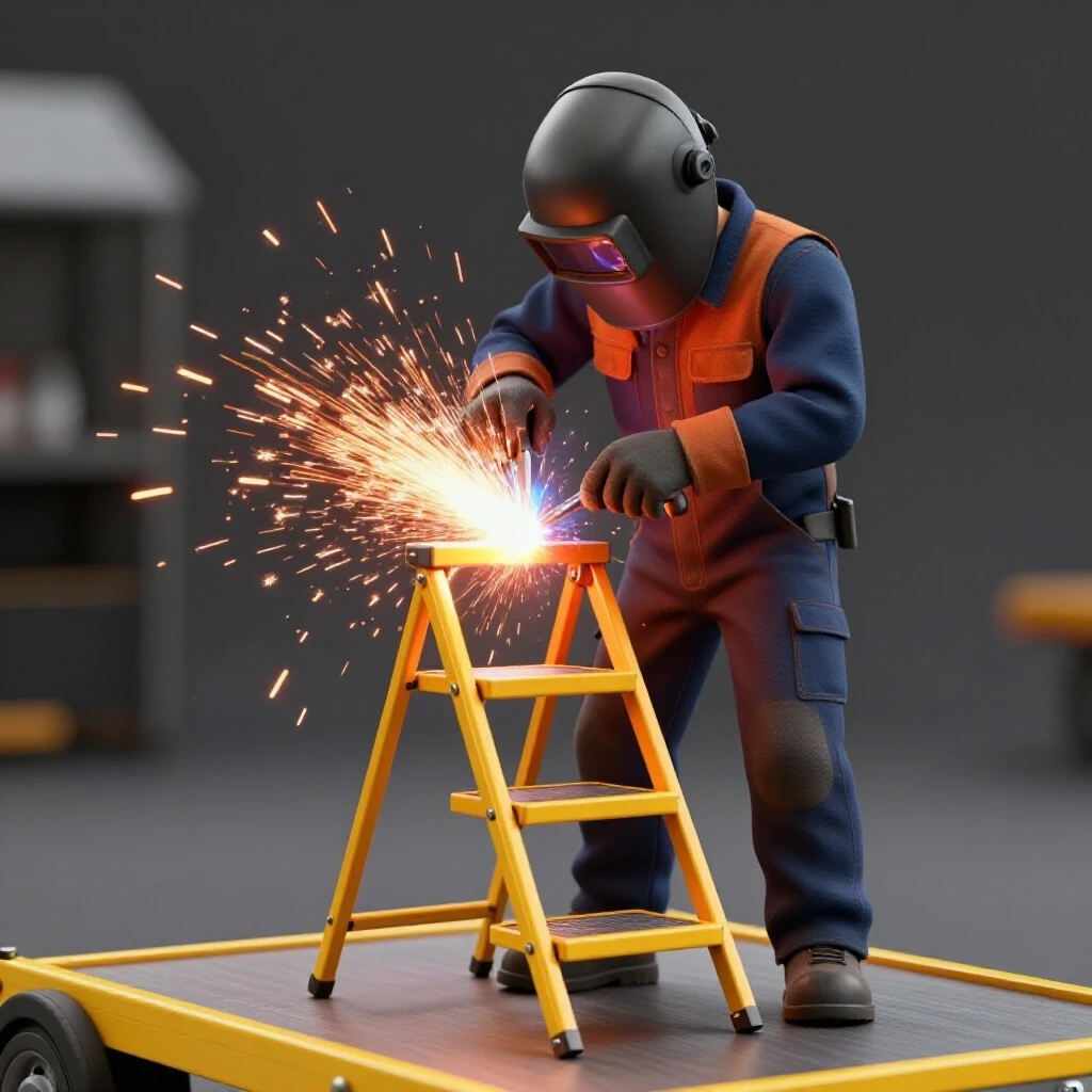
Weld sequencing layout is the strategic order in which you place your welds to balance the internal stresses caused by heating and cooling. Every weld “pulls” the metal toward the side of the bead. If you weld all the way around one joint before moving to the next, you will pull the frame out of alignment.
Metal warping solutions start with the tack weld. A tack weld is a small, temporary bead about 1/4 inch long that holds the parts together. I never do a full weld until the entire project is tacked and checked for squareness.
The Proper Tacking Sequence
- Step 1: Place one tack on the “inside” of each corner of your frame.
- Step 2: Re-check your diagonal measurements.
- Step 3: Place a second tack on the “outside” of each corner.
- Step 4: Place tacks on the top and bottom of the joints.
- Step 5: Final squareness check before running full beads.
| Weld Stage | Purpose | Movement Risk |
|---|---|---|
| Initial Tacks | Hold basic shape | Low |
| Secondary Tacks | Lock in squareness | Moderate |
| Root Passes | Structural bond | High |
| Cover Passes | Final strength/Aesthetics | Very High |
Managing Angular Distortion
Angular distortion happens when the top of a weld cools faster than the bottom, causing the metal to “fold” toward the weld. To combat this, I use a technique called “back-stepping.” Instead of welding in one long continuous line, I break the weld into 2-inch segments, moving from the finished end of the joint back toward the start. This distributes the heat more evenly across the tubing.
Integrating Heavy-Duty Storage Components
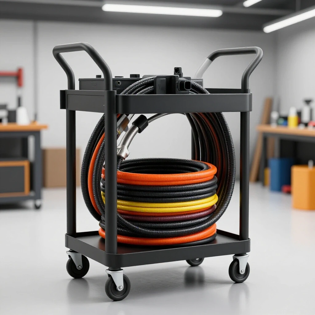
When building a cart meant to organize heavy leads and hoses, the structural design must account for “cantilevered loads.” This is weight that hangs off the side of the frame, which can cause the cart to tip or the frame to twist if not properly braced.
I prefer to use large-diameter hooks for lead storage. If the radius of the hook is too small, it can cause the internal copper of the leads to fatigue over time. A 4-inch diameter pipe section cut into thirds makes an excellent saddle for hanging heavy cables.
Designing for Weight Distribution
- Lower Center of Gravity: Place the heaviest items, like the power unit or the base plate, as low as possible.
- Caster Placement: Mount casters directly under the vertical supports of the frame to transfer the load straight to the floor.
- Triangulation: If your lead storage hooks are tall, add a diagonal gusset (a triangular piece of plate) to the joint to prevent the hook from bending the vertical upright.
Selecting and Mounting Casters for Mobility
The mobility of your project depends entirely on the quality of your casters. For a shop environment, I always choose polyurethane wheels over rubber. Polyurethane won’t develop “flat spots” if the cart sits in one place for too long, and it rolls over metal shavings and floor debris much easier.
Caster Mounting Benchmarks
- Weight Capacity: Ensure each caster is rated for at least 50% of the total projected weight of the cart. This provides a safety margin if the floor is uneven and only three wheels are touching.
- Mounting Plates: Weld a 3/16-inch thick plate to the bottom of your tubing corners. Drill and tap these plates or use through-bolts. Never weld the caster directly to the frame; you will eventually need to replace them.
- Locking Mechanism: At least two casters should have total-lock brakes that stop both the wheel rotation and the swivel.
Final Straightening and Finishing Techniques
Even with the best weld sequencing layout, you may still experience minor warping. If a corner is slightly “high,” you can use “flame straightening.” This involves heating a small spot on the opposite side of the warp with an oxy-fuel torch. As the spot cools, it shrinks and pulls the metal back into alignment. Use this sparingly, as excessive heat can weaken the steel’s structural integrity.
Post-Weld Cleanup and Protection
- Grinding: Use a 40-grit flap disc to smooth out the welds. Avoid removing too much material, as this can weaken the joint.
- Degreasing: Wipe the entire frame down with acetone or a dedicated wax and grease remover. Steel from the mill is covered in “mill scale” and protective oils that will prevent paint from sticking.
- Coating: I prefer a high-quality industrial enamel or a DIY powder coat. If you are working in a garage, a self-etching primer followed by several light coats of implement paint provides a durable finish that resists scratches from dragging hoses.
Practical Tracking Framework for Your Build
To stay organized during custom fabrication projects, I use a simple checklist. This prevents the “I forgot to weld the bottom” syndrome that happens when you get into a rhythm.
- Verify Cut List: Measure twice, cut once.
- Deburr All Edges: Remove the sharp “burr” left by the saw to ensure tight fitment.
- Layout and Scribe: Mark all joint locations clearly.
- Jig Setup: Clamp the base frame to the table or fixture.
- Tack and Square: The most critical step. Do not skip the diagonal check.
- Weld Sequence: Follow the alternating pattern to manage heat.
- Add Accessories: Weld on your hose hooks, lead racks, and handle.
- Caster Install: Bolt on the wheels and check for a level roll.
- Paint and Finish: Protect your hard work from rust.
Lessons from the Shop: Avoiding Common Pitfalls
One mistake I see often is “over-welding.” You don’t need a massive, bulging bead on every inch of a cart frame. A well-penetrated 3/16-inch fillet weld is more than enough for 11-gauge tubing. Excessive welding just adds more heat, which leads to more warping.
Another issue is ignoring the “fit-up.” If you have a 1/8-inch gap in a joint, the weld has to bridge that gap. As that large volume of molten metal cools, it will pull significantly more than a tight-fitting joint. I aim for a fit-up so tight that I have to lightly tap the pieces into place with a dead-blow hammer.
Metal Kerf Allowances by Cutter Type
| Tool Type | Average Kerf (Inches) | Precision Level |
|---|---|---|
| Abrasive Chop Saw | 0.125 | Low |
| Portable Band Saw | 0.035 | Medium |
| Vertical Band Saw | 0.063 | High |
| Cold Saw | 0.095 | Very High |
| Plasma Torch (Hand) | 0.060 – 0.100 | Variable |
Conclusion and Next Steps
Building a durable, mobile station for your shop equipment is a rite of passage for any fabricator. It is the perfect project to practice the skills of layout, heat management, and structural design. By focusing on the physics of the weld and the precision of the layout, you can create a tool that serves your workshop for decades.
Your next step is to clear off your workbench and verify your measurements. Start by building the base rectangle. Once you have a square, flat base, the rest of the project will naturally follow that foundation. Don’t rush the tacks, and always keep your tape measure handy.
Frequently Asked Questions
Why does my frame always twist even when I use clamps?
Clamps hold the metal in place while the weld is liquid, but the real movement happens as the weld cools and shrinks. If you remove the clamps too early, the internal stresses will pull the metal. Always let the joint cool to the touch before releasing the clamps. Also, ensure you are welding in an alternating sequence to balance the pulling forces.
What is the best material for a mobile equipment cart?
For most DIY shop projects, 1.5-inch square tubing with a 1/8-inch wall thickness (11-gauge) is the “sweet spot.” It offers excellent structural rigidity without being excessively heavy. For the shelves or skin, 14-gauge or 16-gauge sheet metal is usually sufficient.
How do I fix a frame that is already warped?
You can use a “cold straighten” method by using a hydraulic jack or a large vise to physically bend the metal back. Alternatively, you can use “heat shrinking.” Heat a small, V-shaped area on the side opposite the warp. As it cools, it will pull the frame back toward the heat.
Should I miter my corners or use butt joints?
Miter joints (45-degree cuts) look more professional and provide more surface area for the weld, but they are harder to cut accurately. Butt joints (90-degree cuts) are much easier for beginners to square up. If you use butt joints, remember to use plastic end caps or weld-on “end plates” to seal the open tube ends.
How many tack welds are enough for a joint?
For 1.5-inch tubing, I recommend four tacks—one on each flat side of the tube. Place them in the center of the flats rather than on the corners. This allows the corners to be welded in a continuous bead later for maximum strength.
How do I prevent the casters from wobbling?
Wobble usually happens because the mounting surface isn’t flat or the casters are of poor quality. Always use a thick mounting plate (at least 3/16″) and ensure your frame base is perfectly flat before welding the plates on. Using casters with “total lock” brakes also helps stabilize the cart when it is in use.
Why is my scribe better than a marker for layout?
A marker leaves a line that is roughly 0.040 to 0.060 inches wide. If you cut on the left side of the line on one end and the right side on the other, you could be 1/8 of an inch off. A carbide scribe makes a line that is only 0.005 inches wide, giving you a much more precise target for your saw blade.
What is “draw” in welding?
“Draw” is the term fabricators use to describe how a weld pulls the metal as it cools. For example, a fillet weld in a T-joint will “draw” the vertical piece toward the weld bead. You can compensate for this by “pre-setting” the piece a few degrees in the opposite direction before welding.
How do I calculate the total weight capacity of my cart?
Add the weight of the steel frame, the equipment, and the maximum weight of the leads or hoses. Divide this total by the number of casters (usually four), then add a 25% safety factor. This ensures that even if the weight shifts to one side, the casters won’t fail.
Does the type of welding (MIG vs. TIG) affect warping?
Yes. TIG welding generally puts more total heat into the part because the process is slower, which can lead to more warping if not managed. MIG welding is faster and often results in a smaller heat-affected zone (HAZ), which can help minimize distortion in thinner materials.
(This article was written by one of our staff writers, Robert Kline. Visit our Meet the Team page to learn more about the author and their expertise.)