How to Build a Rigid Metal Stand for a Router Table (Guide)
I remember the first time I tried to weld a heavy-duty shop base. I had spent hours measuring, cutting, and deburring 2-inch square tubing. Everything looked perfect on the floor. But after I finished my final beads and the metal cooled, I realized the entire frame had twisted nearly half an inch. One leg was floating in the air, and the top was as flat as a potato chip. It was a humbling lesson in how heat behaves.
In my 13 years as a prototype technician and fabricator, I’ve learned that metal isn’t a static material. It’s alive. When you hit it with an arc, it expands. As it cools, it shrinks with incredible force—enough to bend thick steel like it’s a wet noodle. For a stationary tool base that needs to support 300 pounds or more, that movement is your biggest enemy. If the top isn’t dead flat, your workpieces will catch on the edges of the table, ruining your cuts and your patience.
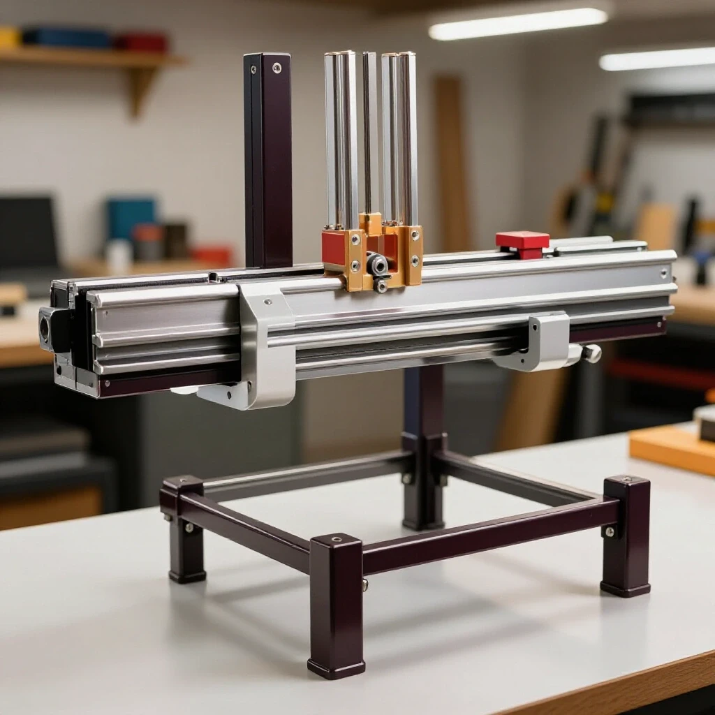
This build log covers the process of fabricating a stationary, high-stiffness support structure for a heavy shop tool. We aren’t just sticking metal together; we are managing thermal forces to ensure the final product is square, level, and rock-solid. We will focus on material selection, precise layout techniques, and a specific weld sequencing layout to keep things straight.
Designing the Framework for Maximum Stiffness
Planning the geometry and material specs ensures the structure handles heavy vibration and weight without flexing. A tool base must be rigid enough to resist the lateral forces generated during use while providing a flat mounting surface for the top.
When I plan these custom fabrication projects, I start with a height target of 36 to 42 inches. This range is the sweet spot for most users, allowing for a comfortable working position. For the main vertical legs and the perimeter of the top frame, 2-inch square steel tubing with a 1/8-inch (11-gauge) wall thickness is the industry standard. It provides a high strength-to-weight ratio and plenty of surface area for strong welds.
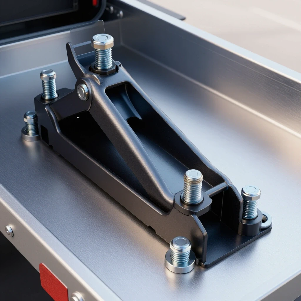
For the internal supports where the table surface actually bolts down, I prefer 1.5-inch angle iron. This allows the tabletop to sit recessed or flush, depending on your design, and gives you a flat flange to drill through. I also factor in flat bar stock for the foot pads. Using 1/4-inch thick flat bar for feet ensures the weight is distributed and gives you a solid place to tap threads for leveling feet or vibration-damping pads.
Material List and Estimated Costs
- 2-inch x 2-inch x 1/8-inch Square Tubing (24 feet): $90 – $120
- 1.5-inch x 1.5-inch x 3/16-inch Angle Iron (10 feet): $30 – $45
- 3-inch x 1/4-inch Flat Bar (2 feet): $15 – $20
- Consumables (MIG wire, shielding gas, grinding discs): $25
- Total Estimated Material Cost: $160 – $210
Calculating Kerf and Material Yields
Accounting for the thickness of the saw blade and maximizing the use of raw stock lengths reduces waste and cost. Every cut you make removes a small amount of metal, which can add up over a dozen cuts and throw off your final dimensions.
In fabrication, “kerf” is the width of the material removed by the cutting tool. If you need four legs at exactly 34 inches and you don’t account for the 1/8-inch blade thickness of a chop saw, your last leg will be nearly half an inch short. I always mark my lines and then cut on the “waste side” of the line. This ensures the finished piece matches the blueprint exactly.
| Cutter Type | Typical Kerf Width | Best Use Case |
|---|---|---|
| Cold Saw | 0.080″ – 0.100″ | Extreme precision and clean finishes |
| Abrasive Chop Saw | 0.125″ (1/8″) | Rough framing and fast breakdown |
| Horizontal Band Saw | 0.035″ – 0.050″ | Accurate square cuts with minimal waste |
| Plasma Cutter | 0.040″ – 0.060″ | Complex shapes and thick plate |
When you are planning your cuts, always measure from the same end of the stock. Do not “chain-measure” where you mark the first piece, then mark the second piece starting from the first mark. Errors will compound. Instead, pull your tape measure once and mark all your cut points based on the cumulative length plus the kerf for each cut.
Building Workshop Jigs for Accurate Squareness
Creating temporary alignment tools holds metal components in place during the critical tack-welding phase. Without a jig, the magnetic pull of the arc and the cooling of the tack will move your parts before you even start the main bead.
I don’t rely on my eyes to determine what is square. I use workshop jigs and fixtures. A simple but effective jig for a rectangular frame is a “corner fixture.” You can make this by clamping two pieces of known-square heavy angle iron to your welding table. By nesting your tubing into this corner, you force the joint to stay at 90 degrees while you tack it.
If you don’t have a dedicated welding table, you can create a layout fixture on a flat concrete floor using heavy-duty magnets and locking C-clamps. However, be careful with magnets; they can cause “arc blow,” where the magnetic field pulls the welding arc away from the joint. I prefer using mechanical clamps and “F-style” welding clamps. For this project, I recommend checking squareness by measuring diagonals. If the distance from the back-left corner to the front-right corner is identical to the distance from the back-right to the front-left, your frame is square within 1/16th of an inch.
Managing Thermal Expansion and Weld Shrinkage
Understanding how heat causes metal to move allows you to use specific bead patterns to counteract those forces. Metal warping solutions are not about stopping the movement entirely, but rather making the metal work against itself to stay straight.
When you weld a joint, the molten puddle is at its largest volume. As it transitions to a solid and cools to room temperature, it undergoes “angular distortion.” This means it pulls the two pieces of metal toward the side where the weld was placed. If you weld the entire outside of a frame first, the corners will pull inward, and the whole structure will “bow” like a ribcage.
To combat this, I use a specific weld sequencing layout. I start with small, 1/4-inch tacks on all four corners of a joint. I don’t just tack one corner and move on. I tack the top, then the bottom, then the sides. This balances the initial pull.
The Physics of the Pull: Shrinkage Rates
- Transverse Shrinkage: Shrinkage perpendicular to the weld line. This usually accounts for 1/32″ to 1/16″ of movement per joint.
- Longitudinal Shrinkage: Shrinkage along the length of the weld. This is what causes long tubes to “banana” or bow.
- Angular Distortion: The “hinge” effect that pulls parts out of square.
I use a “star pattern” or “cross-sequencing” method. If I am welding the four legs to the top frame, I weld the front-left leg, then the back-right leg, then the front-right, and finally the back-left. By jumping across the project, I allow the heat to dissipate and prevent one side of the frame from becoming significantly hotter than the other.
Executing the Weld Sequence for a Rigid Base
Following a strict order of operations ensures that the heat is distributed evenly across the structure. This is the most critical phase for maintaining dimensional tolerances of +/- 1/16th of an inch.
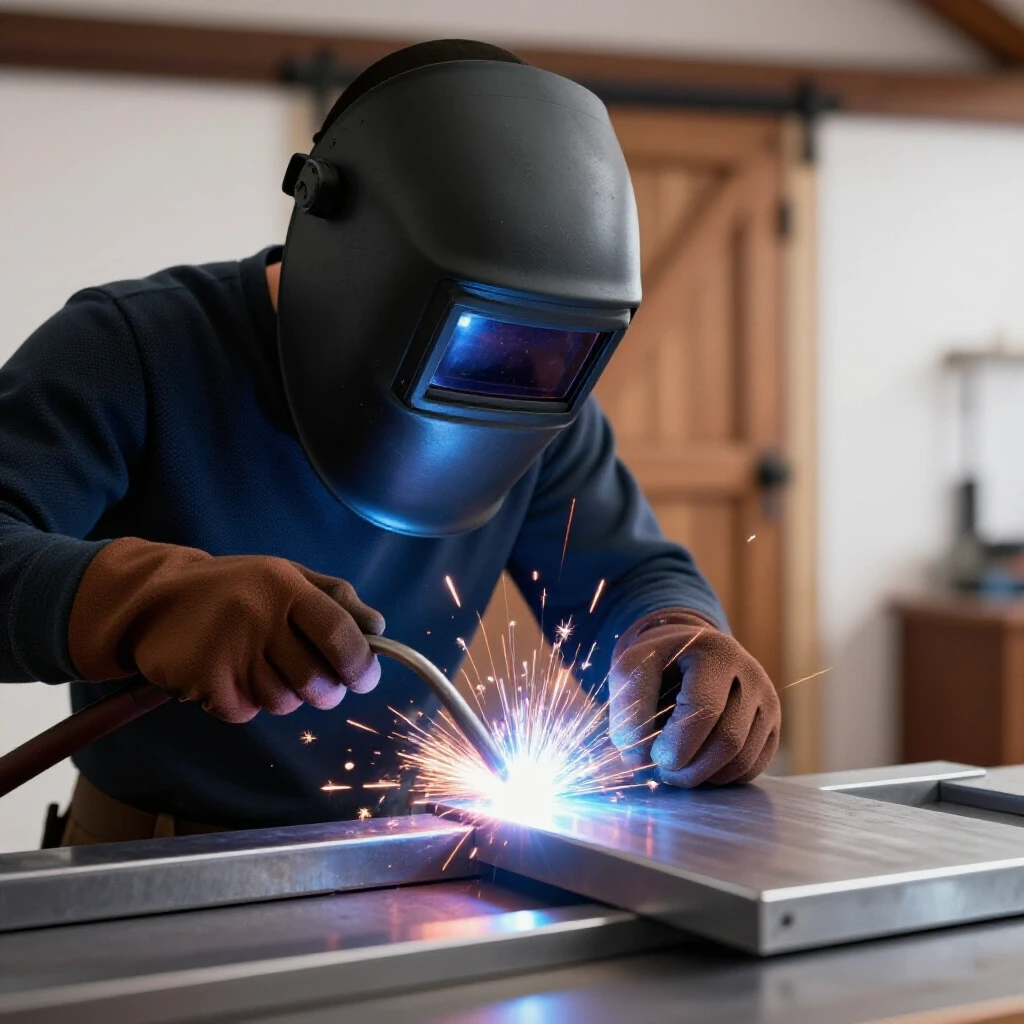
Once the frame is tacked and the diagonals are confirmed, I begin the final passes. For a heavy tool stand, I prefer MIG welding for its speed and deep penetration, though TIG is excellent for thinner wall tubing where heat control is paramount. I never weld a full joint in one go. Instead, I weld in 1-inch to 2-inch “segments.”
Step-by-Step Weld Sequence Checklist
- Tack all primary joints: Use four tacks per joint, placed 90 degrees apart.
- Verify Diagonals: Ensure the frame hasn’t shifted during tacking.
- Root Passes on Vertical Legs: Weld the inside corners of all four legs first. This pulls the legs slightly “in,” which will be countered by the outside welds later.
- Opposing Outside Corners: Move to the outside of the joints, following the cross-pattern mentioned earlier.
- Top and Bottom Flats: Complete the horizontal welds on the top and bottom of the tubing.
- Cooling Phase: Allow the frame to air-cool completely. Never quench a weld with water, as this can embrittle the steel and cause immediate cracking or extreme warping.
During this process, I keep a “Post-Weld Alignment Log.” I measure the height of each leg and the flatness of the top after every few welds. If I see a corner starting to lift, I can adjust my next weld to pull it back down. This proactive approach is much easier than trying to fix a warped frame with a sledgehammer later.
Strengthening the Chassis with Gussets and Cross-Bracing
Adding triangular supports and horizontal bars increases the load-bearing capacity and eliminates lateral movement. A stand might be square, but without bracing, it will “rack” or sway when you are pushing a heavy workpiece across the top.
For this stationary base, I add horizontal stretchers about 8 to 10 inches up from the floor. These join the four legs together, creating a secondary box structure. This significantly increases the rigidity. To further prevent vibration and swaying, I use 1/4-inch flat bar to create gussets at the top corners. A gusset is a triangular reinforcement that bridges the 90-degree angle between the leg and the top frame.
Even a small 3-inch by 3-inch gusset increases the surface area of the joint and provides a massive boost in structural integrity. When welding gussets, I tack them in the center first, then weld from the ends toward the center. This “back-stepping” technique minimizes the chance of the gusset pulling the leg out of plumb.
Vibration Damping and Final Leveling
The final steps involve preparing the contact points where the stand meets the shop floor. Since no garage floor is perfectly flat, a rigid metal stand needs a way to compensate for uneven surfaces to prevent rocking.
I weld 3-inch squares of 1/4-inch flat bar to the bottom of each leg. In the center of these plates, I drill and tap a 1/2-inch hole. This allows me to thread in heavy-duty leveling feet. For a tool that generates high-frequency vibrations, I recommend feet with a thick rubber or polyurethane base. These “damping pads” absorb the energy from the motor, preventing the stand from “walking” across the floor and reducing the noise in your shop.
After the leveling feet are installed, I place the stand in its permanent home and use a machinist’s level to check the top frame. I adjust the feet until the frame is level in both directions. Only then do I bolt the final tabletop surface to the angle iron supports. By waiting until the frame is leveled on the floor, you ensure that you aren’t introducing any “pre-stress” into the tabletop, which could cause it to bow over time.
Accurate Square Cuts and Metal Layout Tips
Precision begins with the first mark on the steel. Many builders struggle with “creeping” dimensions because they use thick markers or don’t account for the thickness of their square.
I always use a carbide-tipped scriber or a very fine silver pencil for my layout. A standard Sharpie line can be 1/16th of an inch wide; if you cut on the wrong side of that line, you’ve already doubled your tolerance error. When using a square, I make sure the “fence” of the square is pulled tight against the factory edge of the tubing.
Another tip for accurate square cuts is to check your saw. Before starting a project like this, I take five minutes to “square the blade.” I use a known-good square to ensure the blade is at exactly 90 degrees to the fence and the table. If your saw is off by even half a degree, a 30-inch leg will be visibly tilted, making the assembly process a nightmare.
Addressing Common Construction Pitfalls
Even with a perfect plan, things can go wrong. Recognizing these issues early allows you to correct them before they become permanent fixtures of your build.
One of the most common mistakes is “over-welding.” It’s tempting to lay down a massive, thick bead on every joint, thinking it makes the stand stronger. In reality, more weld metal means more heat, and more heat means more warping. For 1/8-inch tubing, a 3/16-inch fillet weld is more than enough to achieve full structural strength. Anything more is just adding unnecessary distortion.
Another pitfall is ignoring “mill scale.” This is the dark, flaky oxidation on the surface of hot-rolled steel. If you weld over mill scale, you’ll get a “dirty” arc, poor penetration, and potential weld failure. I always use a flap disc on an angle grinder to clean the steel to “bright metal” at least one inch back from every weld zone. This ensures a clean, strong bond and makes the welding process much smoother.
Final Finishing and Rust Prevention
Once the fabrication is complete and the stand is leveled, it needs protection. Raw steel will begin to rust almost immediately, especially in a humid garage or workshop.
I start by wiping the entire frame down with a degreaser or acetone to remove any oils from the manufacturing process. Then, I apply a high-quality primer. For shop furniture, I’ve found that a “hammered” finish paint works best. It’s durable, hides small imperfections in the metal or welds, and is easy to touch up if you scratch it later.
Summary of Key Metrics for the Build
- Target Height: 36″ – 42″
- Load Capacity: 300+ lbs
- Material: 2″ x 2″ x 1/8″ Square Tubing
- Dimensional Tolerance: +/- 1/16″
- Weld Size: 3/16″ Fillet
- Tack Spacing: 4 tacks per 2″ joint
Building a rigid, stationary tool support is a rite of passage for any serious DIY fabricator. It teaches you to respect the physics of heat and the importance of a precise layout. By following a structured sequence and focusing on stiffness rather than just “sticking metal together,” you create a piece of shop equipment that will last a lifetime and provide a stable foundation for your most accurate work.
Frequently Asked Questions
Why is my frame rocking even though I measured all the legs to the same length?
Even if your legs are identical, the floor likely isn’t. Additionally, if you didn’t use a weld sequencing layout, one side of the frame may have “pulled” upward during cooling. This is why leveling feet are essential for any stationary metal stand. They allow you to compensate for both floor irregularities and minor fabrication warping.
Can I use thinner metal, like 16-gauge tubing, to save money?
I don’t recommend it for a tool base. While 16-gauge is lighter and cheaper, it is much harder to weld without burning through, and it lacks the mass needed to dampen vibrations. Thinner walls also tend to warp significantly more under the heat of the weld. Sticking with 1/8-inch (11-gauge) provides the necessary rigidity for a 300-pound load.
How do I fix a part that has already warped out of square?
If the warp is minor, you can sometimes “counter-weld.” By placing a bead on the opposite side of the warp, the cooling force can pull the metal back toward the center. For more severe warps, you may need to use a “flame straightening” technique with a torch or, in worst-case scenarios, cut the weld and start over with better clamping.
Do I really need gussets if my welds are strong?
Yes. Welds are great at holding pieces together, but they are not always great at resisting leverage. A 40-inch leg acts like a giant lever. Without gussets or cross-bracing, the lateral force can put immense stress on the weld neck, leading to “racking.” Gussets distribute that force over a larger area.
What is the best way to ensure the top frame is perfectly flat?
The best method is to weld the top frame on a known-flat surface, like a thick steel welding table or a heavy granite slab. If you don’t have one, you can use “shimmed” supports on your floor. Use a long straightedge to check for high spots and adjust your weld sequence to pull high corners down.
Should I weld the internal angle iron supports before or after the main frame?
Weld the main “box” or perimeter frame first. Once the outer structure is square and tacked, then fit and weld the internal angle iron supports. This prevents the internal pieces from interfering with the squaring of the primary chassis.
How many tacks are necessary for a 2-inch square tube joint?
I recommend four tacks—one in the center of each of the four sides. This provides enough mechanical strength to hold the piece while allowing you to check squareness. If a joint is only tacked on one or two sides, it will almost certainly pivot when you start the final bead.
Is MIG or TIG better for this type of workshop project?
MIG is generally better for this build because it is faster and provides excellent penetration on 1/8-inch steel. TIG is great for precision, but the slower travel speed puts more total heat into the metal, which can actually increase the amount of warping if you aren’t extremely careful with your heat management.
How do I prevent the drill bit from “walking” when I’m drilling holes for the feet?
Always use a center punch to create a divot before drilling. For 1/2-inch holes in 1/4-inch plate, start with a small “pilot” bit (about 1/8-inch) and then move up to the final size. This ensures the hole stays centered and the bit doesn’t wander across the plate.
Why does my weld look porous or “bubbly”?
This is usually caused by poor gas coverage or dirty metal. Ensure your shielding gas is turned on and set to about 20-25 CFH (cubic feet per hour). Most importantly, make sure you have ground off all mill scale and rust to reveal shiny, clean steel before you start.
(This article was written by one of our staff writers, Robert Kline. Visit our Meet the Team page to learn more about the author and their expertise.)