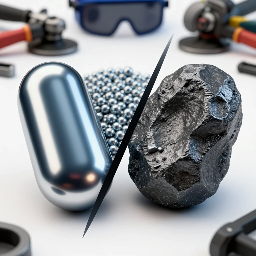
Metal Cutting Bandsaw vs Abrasive Chop Saw (Comparison)
There is a specific kind of frustration that settles in when a project hits a wall because of a bad cut. You have spent hours on a layout, only to find that your weld fit-up is gapped or your material has hardened so much that a file won’t touch it. In my 18 years of troubleshooting industrial fabrication setups, I have learned that the choice between a continuous-loop blade machine and a high-speed abrasive disc cutter is rarely about price. It is about how each method influences the mechanical and metallurgical integrity of the final assembly. When a machine begins to chatter or a cut wanders off-square, you aren’t just looking for a quick fix; you are looking for the root cause in a system of variables.
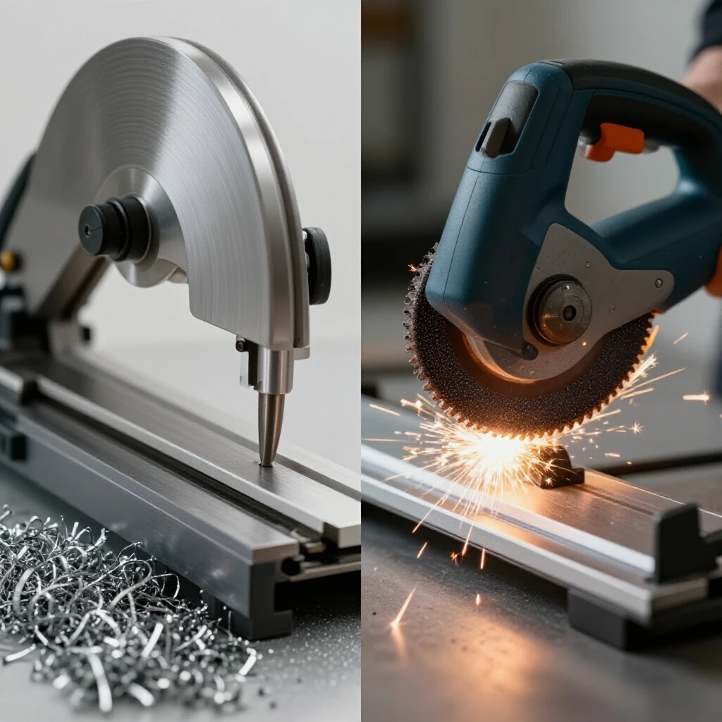
Mastering Systematic Diagnostic Frameworks for Shop Machinery
A systematic diagnostic framework is a structured approach to identifying machine failures by isolating variables one at a time. This process involves observing the symptom, checking mechanical baselines like alignment and tension, and using data to rule out suspected faults. It prevents the common mistake of replacing parts or changing settings based on guesswork.
In my experience, troubleshooting a fabrication issue starts with a clean slate. I treat every machine malfunction as a puzzle where the pieces are mechanical tolerances, electrical stability, and material science. When you are comparing the performance of a horizontal loop-blade saw against a high-speed friction cutter, you have to look at the “fingerprints” each machine leaves on the metal.
If a cut is coming out crooked, I don’t just tighten the vise. I look at the blade tracking and the pivot point harmonics. Building a diagnostic path means starting with the most likely culprit—usually human error or basic maintenance—and moving toward complex issues like motor controller frequency interference or metallurgical work-hardening. This methodical approach is the only way to minimize downtime and ensure that a fixed machine stays fixed.
Troubleshooting Mechanical Alignment and Squaring Faults
Mechanical alignment refers to the precise geometric relationship between the cutting tool, the machine frame, and the workpiece. In cutting operations, squaring faults occur when the tool path deviates from the intended vertical or horizontal plane, often due to worn guides, loose pivots, or frame flex.
When I am called to a shop where a continuous-loop machine is “bellying” its cuts, the first thing I check is the blade tension and guide spacing. A common mechanical troubleshooting step is to use a digital dial indicator to measure the deflection of the blade under load. If the blade guides are set too far apart, the blade will twist as it enters the material, creating a curved cut that is impossible to weld cleanly. I aim for a mechanical tolerance of no more than 0.002 inches of lateral play in the guide bearings.
For high-speed friction cutters, alignment issues often stem from the pivot arm. Over years of use, the bushings in the main hinge can wear down, allowing the disc to cant to one side. I use a machinist’s square to check the relationship between the disc face and the base plate. If there is a gap, I don’t just shim the vise; I rebuild the pivot. Interestingly, a disc that is out of alignment doesn’t just cut crooked; it creates uneven side-loading that can lead to catastrophic disc failure.
- Check guide bearing clearance: 0.001 to 0.003 inches.
- Verify blade tension: 25,000 to 30,000 PSI for carbon steel blades.
- Inspect pivot arm play: No detectable movement when shaken by hand.
- Measure vise squareness: Use a 6-inch precision square against the fence.
Isolating Tool Chatter and Resonant Harmonics
Tool chatter is a resonant vibration that occurs when the frequency of the cutting action matches the natural frequency of the machine or the workpiece. This results in poor surface finish, accelerated tool wear, and even structural damage to the machine’s bearings and motor mounts.
I once spent three days chasing a vibration in a large-scale loop-blade saw that turned out to be a harmonic issue caused by the floor being uneven. In a metalworking diagnostic guide, chatter is often categorized by its frequency. Low-frequency chatter usually points to a lack of rigidity in the machine frame or the workpiece clamping. If you are using a friction cutter and the machine starts to “scream” or bounce, it is often a sign of an unbalanced disc or a spindle bearing that has lost its preload.
To resolve these tool chatter solutions, I use a smartphone-based vibration spectrum analyzer to find the peak frequency. If the chatter occurs at a specific RPM, I adjust the feed rate or the blade speed to move the system out of that resonant zone. For loop-blade machines, changing the teeth-per-inch (TPI) can often break up the harmonic pattern. A variable-pitch blade is a great way to prevent the teeth from hitting the material at a rhythmic interval that encourages vibration.
- Low-frequency vibration: Check workpiece clamping and floor mounting.
- High-frequency vibration: Inspect spindle bearings and tool balance.
- Variable pitch blades: Use 4/6 or 5/8 TPI to disrupt harmonics.
- Feed rate adjustment: Increase pressure to “bury” the teeth and dampen movement.
Diagnosing Weld Porosity Linked to Cutting Methods
Weld porosity is a defect characterized by small gas pockets trapped within the weld metal, often caused by surface contaminants or metallurgical changes in the base material. The method used to cut the metal can introduce these contaminants through friction-induced oxidation or the deposition of abrasive particles.
This is where the choice between a cool-cutting loop blade and a hot-cutting abrasive disc becomes critical for weld quality. When you use a friction-based cutter, the intense heat creates a thick layer of oxide on the cut surface. If you don’t grind this back to shiny metal, you are essentially “baking” oxygen and nitrogen into your weld pool. This is a primary cause of troubleshooting weld porosity in high-stakes fabrication.
Furthermore, abrasive discs leave behind tiny fragments of aluminum oxide or silicon carbide embedded in the metal. During the welding process, these particles can vaporize and create gas bubbles. In my repair logs, I have noted that shops switching from abrasive cutting to cold-cutting saws often see a 40% reduction in weld defects. If you must use a friction saw, your metal fabrication fixes must include a rigorous mechanical cleaning of the cut edge with a flapper disc or wire wheel.
| Cutting Method | Thermal Impact | Potential Weld Defect | Required Post-Cut Prep |
|---|---|---|---|
| Continuous-Loop Blade | Minimal (Cold Cut) | Low (Coolant Residue) | Degrease only |
| High-Speed Abrasive Disc | High (Heat-Affected Zone) | High (Oxidation/Porosity) | Grind to bright metal |
| Dry-Cut Carbide Blade | Moderate | Medium (Chip Embedment) | Light deburring |
| Friction Sawing | Extreme | Very High (Carbon Migration) | Heavy grinding/beveling |
Managing Heat-Affected Zones and Metallurgical Hardening
A Heat-Affected Zone (HAZ) is the area of base metal that has had its microstructure and properties altered by intense heat during cutting or welding. Metallurgical hardening occurs when certain steels are heated above a critical temperature and then cooled rapidly, making the edge brittle and difficult to machine.
I have seen many fabricators ruin expensive drill bits trying to put a hole near a cut made by a friction saw. The abrasive disc generates so much localized heat that it essentially “quenches” the edge of the steel, creating a thin layer of martensite. This is a classic metallurgical defect that is hard to diagnose if you aren’t looking for it. A loop-blade saw, by contrast, uses a chip-making process that carries the heat away in the chips, leaving the base metal relatively cool.
If you are seeing cracking in your welds or find that your material is warping during the cutting process, you are likely dealing with excessive thermal input. To test this, I use infrared heat tracking during the cut. If the material exceeds 400 degrees Fahrenheit, you are risking a change in the grain structure. In these cases, switching to a method with a lower IPT (inches per tooth) or using a dedicated cooling system is necessary to maintain structural integrity.
Electrical Load and Motor Performance Diagnostics
Electrical load diagnostics involve measuring the current, voltage, and resistance within a machine’s power system to ensure the motor is operating within its design parameters. Issues like voltage drop or phase unbalance can lead to motor overheating, reduced torque, and intermittent failures.
When a saw motor starts to bog down or trip breakers, I don’t just blame the fuse. I use a multimeter to check for a back-EMF fault or a voltage drop at the outlet. For instance, a high-speed abrasive cutter draws a massive amount of current upon startup. If your shop’s wiring has a high resistance (measured in Ohms), the voltage will sag, and the motor will lose torque, leading to a stalled cut and a glazed disc.
For machines with variable frequency drives (VFDs), I look for electrical gremlins like EMI (electromagnetic interference). If the saw’s power cables are run too close to the controller for a CNC table, it can cause erratic behavior in both machines. Building a diagnostic path for electrical issues requires checking the following metrics:
- Input Voltage: Should be within 5% of the motor’s nameplate rating.
- Amperage Draw: Measure while the saw is under full load; it should not exceed the Full Load Amps (FLA).
- Insulation Resistance: Use a megohmmeter to check for motor winding breakdown.
- Capacitor Health: In single-phase motors, a weak start capacitor is a common failure point for saws that “hum” but won’t spin.
Case Study: Resolving the Mystery of the Wandering Cut
A custom trailer shop was struggling with structural alignment faults on their main chassis rails. They were using a heavy-duty abrasive cutter, but the cuts were consistently 1/8-inch out of square over a 4-inch channel. They had already replaced the spindle and the vise, but the problem persisted. I was brought in to perform a systematic diagnostic.
First, I checked the mechanical baseline. The vise was square to the base, and the pivot was tight. However, when I watched the cut in progress, I noticed the abrasive disc was flexing significantly. We were dealing with “disc runout” caused by the material being too hard for the specific disc grade they were using. The disc was essentially trying to find the path of least resistance, which wasn’t a straight line.
We switched the operation to a horizontal loop-blade machine with a 1-inch wide blade. I set the blade tension to 28,000 PSI and adjusted the guides to within 0.002 inches of the stock. The result was a perfectly square cut. The lesson here is that sometimes the tool itself is the wrong choice for the precision required, no matter how well it is maintained. The abrasive disc was great for speed, but for structural alignment, the rigidity of a tensioned steel blade was the only solution.
Actionable Saw Alignment and Health Checklist
To maintain peak performance and avoid the frustration of failed cuts, I follow a strict calibration checklist every month. This routine helps catch small issues before they become “electrical gremlins” or structural failures.
- Check Table Flatness: Use a precision straightedge to ensure the machine base hasn’t warped or bowed.
- Verify Spindle Runout: Place a dial indicator on the spindle; any movement over 0.001 inches indicates bearing wear.
- Inspect Blade Guides: Look for “grooving” in the carbide inserts or flat spots on the rollers.
- Test Vise Parallelism: Clamp a ground parallel in the vise and indicate across its length to ensure it is parallel to the blade path.
- Measure Motor Temperature: Use an IR thermometer after a long cut; temperatures over 150°F suggest an electrical or friction issue.
- Analyze Chip Shape: In loop-blade machines, chips should be tightly curled and silver. Blue chips indicate too much heat; powdery chips indicate too little feed pressure.
- Check Belt Tension: Ensure drive belts are not glazed or cracked and have roughly 1/2-inch of deflection.
- Verify Squareness: Use the “flip test”—cut a piece of square tubing, flip one side 180 degrees, and butt the cut ends together. Any gap is double the actual error.
Integrating Modern Diagnostic Tools into the Workflow
The days of “eyeballing” a machine’s health are over. To truly master systematic diagnostic methodologies, you need to use the tools available to modern millwrights. I rely heavily on digital dial indicators for checking backlash and smartphone apps for vibrational analysis. These tools provide hard data that removes the emotion from troubleshooting.
For example, if I suspect a motor controller fault, I use a digital oscilloscope to look at the sine wave of the power coming out of the VFD. If the wave is “dirty,” it explains why the motor is running hot and vibrating. Similarly, using a laser alignment tool can make short work of a lathe alignment checklist or a saw-to-table squaring task. These tools are an investment, but they pay for themselves the first time they help you avoid a week of downtime.
Conclusion: Developing a Diagnostic Mindset
Mastering the mechanics of metal cutting is not about choosing the most expensive machine; it is about understanding how to keep that machine in a state of peak calibration. Whether you prefer the raw speed of an abrasive disc or the precision of a continuous-loop blade, the diagnostic principles remain the same. You must observe the symptoms, isolate the variables, and verify your results with measurements.
When you encounter a problem—be it weld porosity, tool chatter, or a wandering cut—take a step back. Don’t reach for the adjustment wrench immediately. Reach for your dial indicator, your multimeter, and your repair log. By treating every mechanical failure as a data-driven investigation, you will not only fix the issue faster but also develop the skills to prevent it from happening again. This systematic approach is what separates a hobbyist from a true master of the craft.
Frequently Asked Questions
Why does my abrasive disc keep breaking or “exploding” during heavy cuts? Disc failure is often caused by side-loading or excessive spindle runout. If the machine’s pivot point is loose, the disc can cant in the kerf, causing it to bind and shatter. Always check your spindle bearings for play and ensure your workpiece is clamped as close to the cut line as possible to prevent vibration.
How do I stop my bandsaw blade from “walking” or cutting at an angle? A wandering cut is usually a sign of low blade tension or improperly adjusted guides. Ensure your blade is tensioned to the manufacturer’s spec (often around 25,000 PSI) and that the guide bearings are close enough to the blade to prevent twisting without causing friction heat. Also, check that your feed rate isn’t too high for the TPI you are using.
What causes “blue” chips when I am using a loop-blade machine? Blue chips are a sign of excessive heat in the cut, usually caused by a blade speed that is too high or a feed rate that is too low. When the teeth rub against the metal instead of cutting into it, friction builds up. Increase your feed pressure or slow down the blade RPM to ensure you are making actual chips that carry the heat away.
Why am I getting porosity in my welds after using a chop saw? Abrasive chop saws generate high heat that creates a layer of oxide on the steel. They also leave behind abrasive dust. If this isn’t ground off to reveal shiny, bare metal, the contaminants will gassify during welding, creating pockets of porosity. Always clean your edges with a wire wheel or grinder after a friction cut.
Can a vibrating motor cause a crooked cut? Yes. High-frequency vibrations (chatter) can cause the cutting tool to “bounce” in the kerf, which leads to a poor finish and can eventually force the tool off-track. Vibration often stems from unbalanced tools, worn motor mounts, or an unanchored machine base.
How often should I check the alignment of my saw? For a professional shop, a quick squareness check should be done weekly. A deep-dive alignment, including checking spindle runout and guide wear, should be performed every 50 to 100 hours of cutting time or whenever you notice a decline in cut quality.
What is the best way to diagnose an electrical “hum” in my saw motor? A motor that hums but doesn’t turn usually has a failed start capacitor or a seized bearing. First, try to turn the spindle by hand (with power disconnected). If it moves freely, the capacitor is likely the culprit. If it’s hard to turn, look for mechanical interference or bearing failure.
Does blade pitch (TPI) affect machine vibration? Absolutely. If the tooth spacing matches the thickness of the material (e.g., only one tooth is in the cut at a time), the blade will “drop” into the gaps, causing severe vibration. You should always have at least three teeth in contact with the material at all times to maintain stability.
Is it better to use coolant on a loop-blade saw? In most cases, yes. Coolant lubricates the cut, reduces friction, and flushes chips out of the kerf. This prevents “chip welding,” where the hot metal chips stick to the blade teeth and ruin the cut finish. However, for some dry-cut carbide machines, coolant can actually cause thermal shock and crack the teeth.
What is the “flip test” for squaring a saw? The flip test is a diagnostic method where you cut a square piece of stock, rotate one half 180 degrees, and press the cut faces together. If the cut is square, the edges will line up perfectly. If there is a gap, the angle of the gap is twice the error of your saw’s alignment, making it very easy to see even small deviations.
(This article was written by one of our staff writers, Paul Whitaker. Visit our Meet the Team page to learn more about the author and their expertise.)