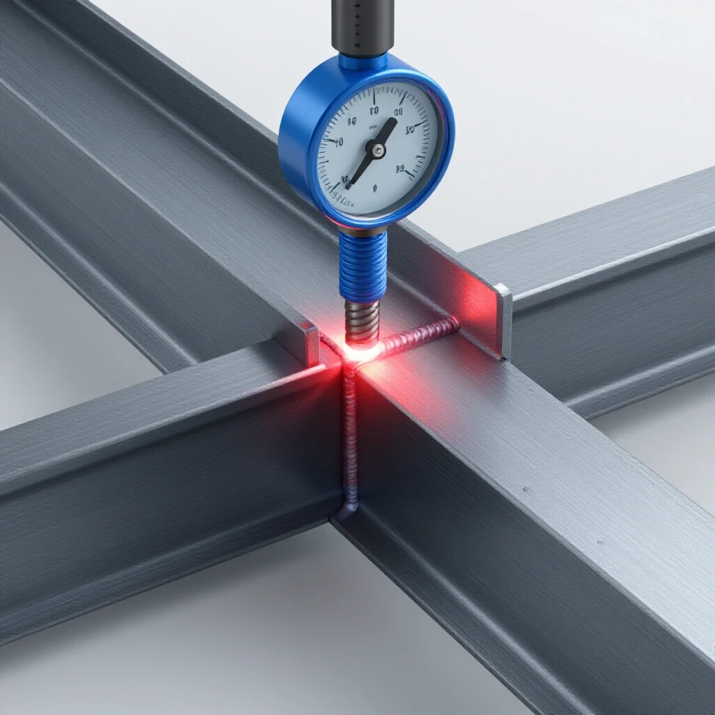
Importance of Beveling Steel Plates Before Welding (Guide)
I’ve spent the better part of 15 years in fabrication shops, and if there is one thing I’ve learned, it’s that a weld is only as good as the work you do before you ever pull the trigger. I remember a project early in my career involving a heavy equipment trailer frame. The welds looked beautiful—stacked like a row of dimes. But three months later, the main structural member cracked right down the middle of the bead. When I ground it out to see what went wrong, the problem was obvious. The fabricator had tried to weld 1/2-inch steel plate with a square edge. The weld had only penetrated about 20% of the material.
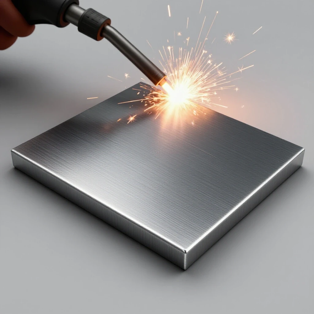
That experience taught me that troubleshooting fabrication failures usually starts with looking at the geometry of the joint. When we talk about preparing steel for a structural load, we are really talking about how to manage physics. If you don’t create a path for the weld metal to reach the root of the joint, you are just gluing the surfaces together. This leads to a host of issues, from structural failure to excessive warpage and even hidden porosity. My goal here is to help you develop a diagnostic mindset for edge preparation so you can stop guessing and start building with confidence.
Systematic Diagnostic Framework for Edge Preparation
A structured approach to evaluating how plate edges are shaped before joining involves observing the material thickness, selecting the appropriate bevel angle, and ensuring the root opening is consistent. This framework prevents you from over-working the metal or under-preparing the joint, both of which lead to rework.
When I walk into a shop to diagnose a weld failure, the first thing I check is the cross-section. If the plate is 6mm or thicker, a square butt joint is almost always the wrong choice. You need to create a “V” or “U” shape to allow the arc to reach the bottom. I use a three-step process: observation of the load requirements, isolation of the material thickness, and control of the edge geometry.
- Observation: Look at the thickness. Anything over 1/4 inch (approx. 6mm) requires a sloped edge for full strength.
- Isolation: Determine if the failure is due to “lack of fusion” at the bottom of the joint.
- Variable Control: Standardize your bevel angles—usually between 30 and 45 degrees—to ensure the torch or electrode has enough room to maneuver.
Building on this, you have to consider the “root face” or the “land.” This is the flat part left at the bottom of the bevel. If you make it too sharp (a knife edge), the heat will blow it away. If it’s too thick (over 1/8 inch), the weld won’t get through it. I aim for a land of about 1/16 to 3/32 of an inch for most manual workshop tasks.
Resolving Poor Weld Fusion with Proper Groove Geometry
Addressing the failure of weld metal to bond with the base plate often stems from an insufficient opening that prevents the arc from reaching the bottom of the joint. This is a classic diagnostic path where the “symptom” is a cracked weld, but the “root cause” is the physical barrier of a square plate edge.
Lack of fusion is the silent killer of fabrication projects. You might see a bead on top, but the core of the metal is still two separate pieces. By sloping the edges of the steel, you increase the surface area for the weld to bite into. This effectively turns a 2D surface into a 3D pocket. Interestingly, the wider the groove, the easier it is to see what you are doing, which naturally reduces the risk of trapping slag or gas.
| Symptom | Root Cause | Diagnostic Fix |
|---|---|---|
| Weld bead “sitting on top” | No groove for penetration | Bevel edges to 37.5 degrees |
| Cracking in the center of the weld | Insufficient throat depth | Increase bevel depth to 100% of thickness |
| Excessive spatter at the root | Angle too narrow for the torch | Widen bevel angle to 45 degrees |
| Slag inclusions | Tight “V” shape trapping debris | Use a wider root opening (1/16″ gap) |
As a result of proper sloping, the arc energy is focused on the root rather than being wasted on the top surface. I’ve found that using a digital protractor to verify your angles can save hours of grinding later. If your angle is too steep (less than 30 degrees), you’ll struggle to get the torch nozzle close enough, leading to poor shielding and potential porosity.
Troubleshooting Mechanical Vibrations in Beveling Tools
Identifying why hand-held or portable tools produce uneven edges or excessive noise is critical for a clean finish. This includes checking for bearing wear, spindle play, and abrasive selection, as a rough or “chattered” edge can lead to stress risers in the finished weld.
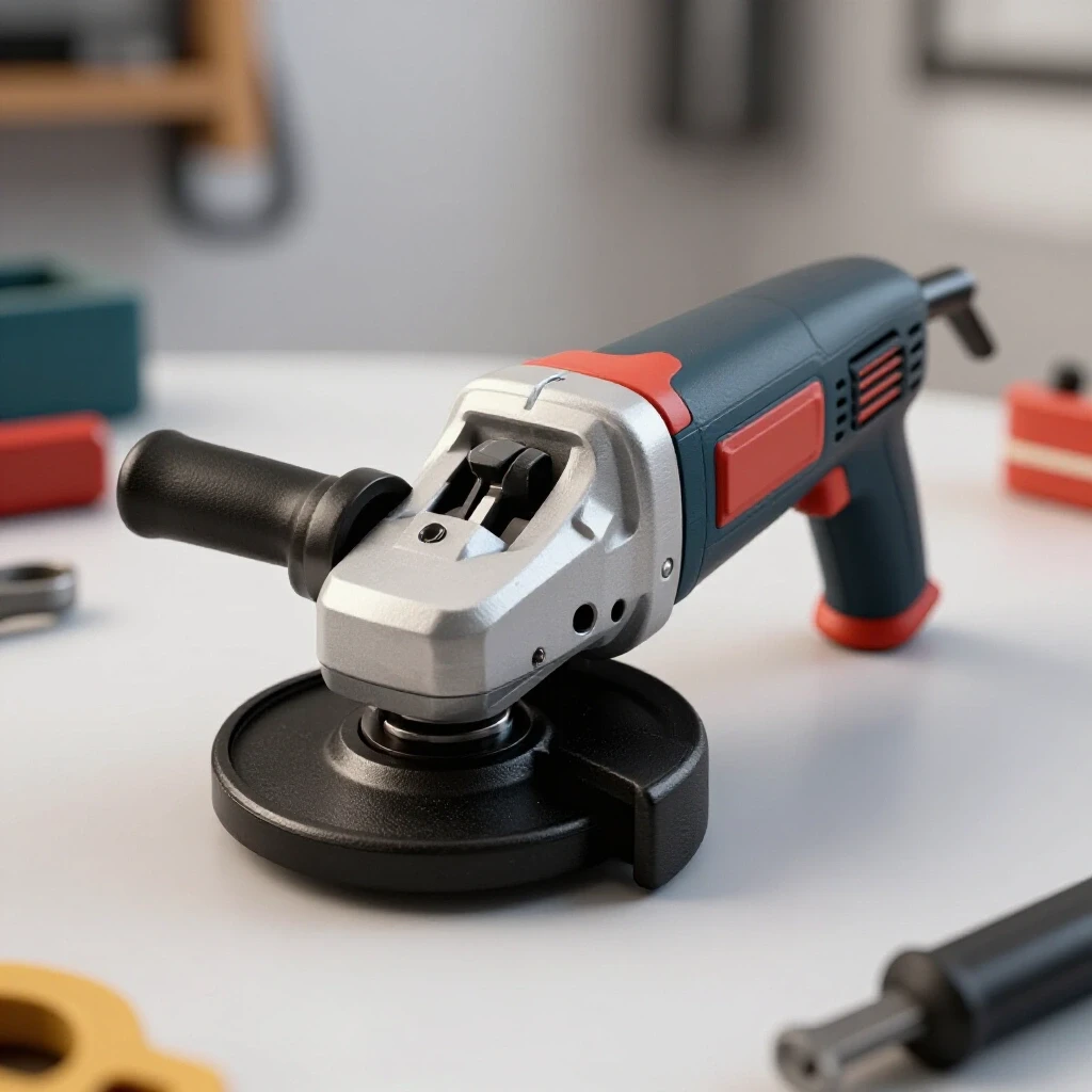
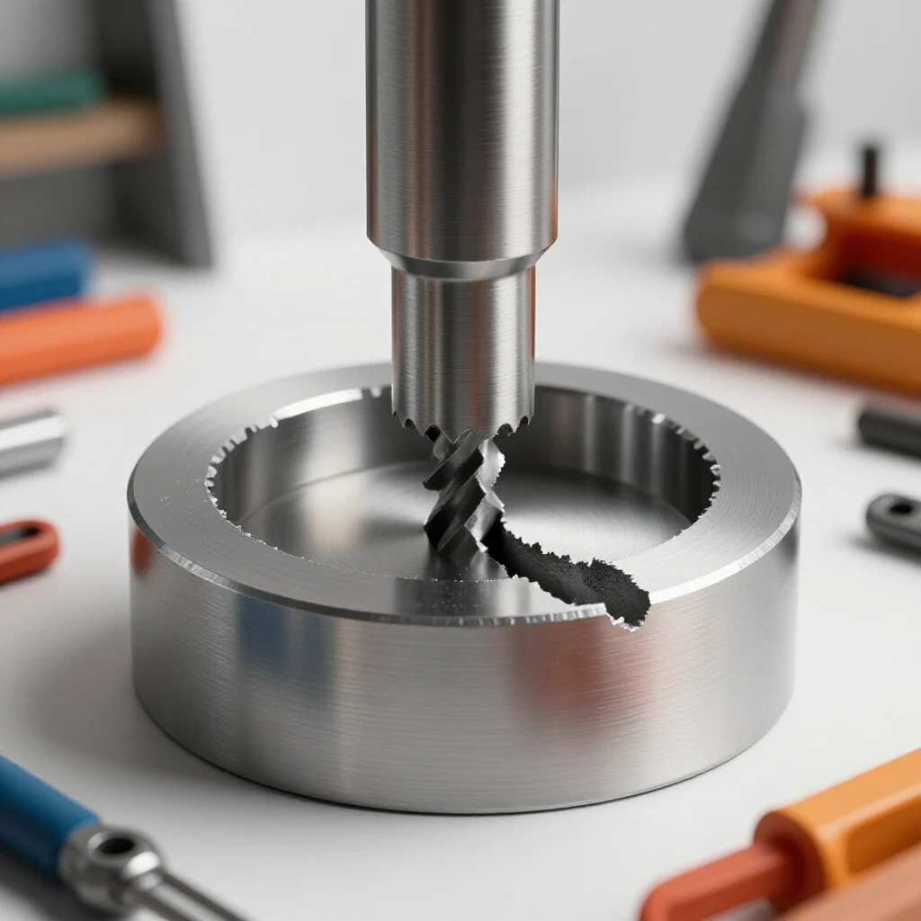
When I’m using a rotary beveler or a high-speed grinder, tool chatter is my biggest enemy. Chatter is essentially a resonant vibration where the tool bounces off the work surface. This happens when the tool’s RPM matches the natural frequency of the plate or when there is “backlash” in the tool’s spindle. In a workshop environment, a spindle backlash of more than 0.003 inches can cause the cutting head to jump, leaving a “wavy” surface.
- Check the Arbor: Ensure the grinding disc or cutter is perfectly centered. A 0.005-inch offset can cause massive vibration at 10,000 RPM.
- Inspect Bearings: If the tool feels hot near the head, the bearings are likely failing, causing the spindle to wobble.
- Evaluate Material Support: A plate that isn’t clamped tightly will vibrate like a tuning fork. Use heavy C-clamps every 12 inches.
- Monitor Feed Rate: Moving too slow causes the tool to rub rather than cut, which generates heat and “glazes” the edge.
I’ve seen many fabricators blame the steel for being “hard” when the real issue was a worn-out grinder bushing. If you notice a “rhythmic” thumping, stop and check the tool. A clean, smooth bevel is much easier to weld than one covered in deep gouges and chatter marks.
Managing Heat-Induced Distortion through Plate Shaping
Controlling how steel moves and warps during the welding process is a major part of fabrication. By removing material at the edges to create a groove, you reduce the total volume of weld metal needed in some cases and, more importantly, you control where the shrinkage forces act.
When you weld two square edges together, the heat is concentrated at the very top. As the weld cools, it shrinks and pulls the top of the plates together, causing them to “peak” or “taco.” By using a double-V bevel (sloping both the top and bottom edges), you can balance these shrinkage forces. I often use this technique on plates over 1/2 inch thick to keep them flat without needing a massive hydraulic press to straighten them later.
- Single-V Bevel: Best for plates 6mm to 12mm. It’s easier to prep but prone to one-directional warping.
- Double-V Bevel: Best for plates over 15mm. It requires more prep time but keeps the part dimensionally stable.
- Root Opening: A 1/8-inch gap allows the plates to shrink into each other rather than pulling against each other.
In my experience, the “pull” of a cooling weld can exert thousands of pounds of force. If your edge prep is inconsistent, that pull will be uneven, leading to a twist in your frame or structure. I always aim for a tolerance of +/- 2 degrees on my bevels to ensure the heat input remains symmetrical across the entire length of the joint.
Isolating Tool Chatter and Surface Irregularities
Determining the cause of a poor surface finish on a beveled edge involves a systematic check of the cutting media and the tool’s mechanical integrity. A jagged or oxidized edge can trap contaminants, leading to the very porosity you are trying to avoid.
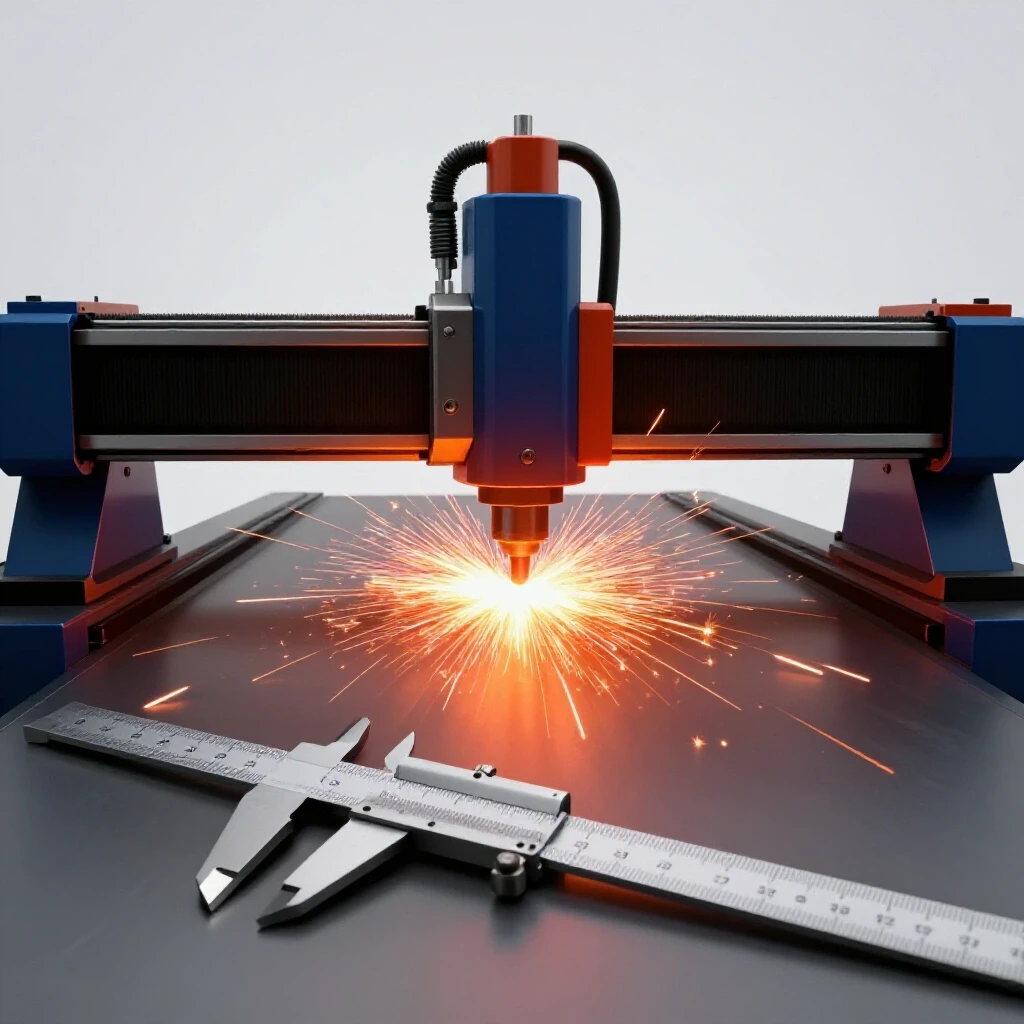
If you are using a plasma cutter to create your bevels, the “dross” or oxide layer left behind is a major diagnostic red flag. This layer has a higher melting point than the base steel. If you don’t grind it off to reveal shiny metal, you’ll end up with “cold lap,” where the weld simply sits on top of the oxide. I recommend a quick pass with a 60-grit flapper disc to ensure the surface is chemically clean.
- Oxidation: Gray or black scale on the bevel face. Must be removed to prevent porosity.
- Gouging: Deep marks from a steady-hand failure. These create “pockets” where slag can hide.
- Inconsistent Land: A root face that varies from 0 to 1/8 inch. This makes it impossible to maintain a consistent weld pool.
Interestingly, I once tracked a recurring porosity issue back to the grinding discs themselves. The fabricator was using “contaminated” discs that had previously been used on aluminum. When he used them to prep the steel plates, tiny bits of aluminum were embedded in the bevel, reacting with the steel during the weld. Always keep your steel-prep tools separate from other materials.
Practical Frameworks for Material Prep Consistency
Establishing a repeatable process for shaping plate edges ensures that every joint behaves the same way under the arc. This reduces the “guesswork” that leads to most workshop errors and allows for faster troubleshooting when something does go wrong.
I like to use a “prep checklist” before I start any major assembly. It sounds tedious, but it saves the frustration of a failed bend test or a structural crack. If I know my bevel is exactly 37.5 degrees and my root face is exactly 1/16 of an inch, and I still get a defect, I can immediately rule out geometry and start looking at other variables like shielding gas or moisture.
- Measure Thickness: Use calipers to confirm the plate is within the mill tolerance (usually +/- 0.010 inches).
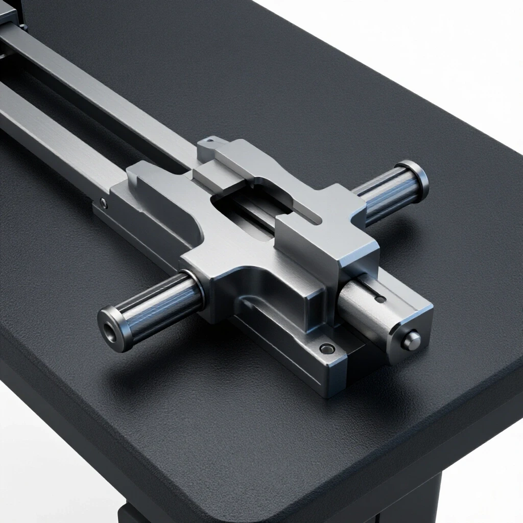
- Select Tool: Choose a rotary beveler for speed or a grinder for complex shapes.
- Set Angle: Use a dedicated bevel gauge or a fixed-angle tool head.
- Clean Surface: Remove all mill scale at least 1 inch back from the edge.
- Verify Root: Use a “gap rod” or a drill bit to ensure the spacing between plates is uniform.
By following these steps, you create a baseline. In mechanical troubleshooting, the baseline is everything. Without it, you are just chasing ghosts. If you are dealing with a 10mm plate, a 35-degree bevel with a 2mm root gap is a solid starting point that provides a good balance between penetration and heat control.
Diagnosing Weld Porosity through Edge Cleanliness
Weld porosity, or the “Swiss cheese” look in a bead, is often blamed on gas flow, but the diagnostic truth is frequently found in the edge preparation. If moisture, oil, or mill scale is trapped in the “V” of the bevel, the heat of the arc will turn those contaminants into gas, which then gets trapped in the cooling metal.
I once spent two days troubleshooting a MIG welder that was producing porous welds. We swapped the gas, the liner, and the wire. Nothing worked. Finally, I looked at the beveled edges of the plates. They had been “cleaned” with a rag soaked in old shop floor solvent. The solvent was leaving a thin oily film in the bottom of the groove. We switched to a dedicated degreaser and a clean wire brush, and the problem vanished.
- Mill Scale: This is the flaky blue/black layer on hot-rolled steel. It is an insulator and will cause arc instability.
- Moisture: Steel is porous on a microscopic level. If it’s been sitting in a cold shop, hit the bevel with a torch to “sweat” out the moisture before welding.
- Hidden Rust: Rust inside the groove can hold oxygen, leading to internal pores that you won’t see until the weld fails.
The goal of a good bevel isn’t just the shape; it’s the quality of the exposed metal. I always aim for a “bright metal” finish. If the bevel looks dull or gray, it isn’t clean enough. A quick check with an infrared thermometer can also tell you if your pre-heat is uniform, which helps in preventing moisture-related porosity in thicker sections.
Frequently Asked Questions
Why can’t I just “turn up the heat” instead of beveling? Increasing the heat (amperage) on a square-edged plate usually results in “undercut” or burning through the top of the plate while the center remains cold. It doesn’t provide the same depth of fusion as a sloped edge. You end up with a wide, weak weld rather than a deep, strong one.
At what thickness is it mandatory to shape the edges? In most structural applications, any steel plate thicker than 3/16 inch (approx. 5mm) should be beveled. For non-structural or thin-gauge work, you can often get away with a square edge and a small gap, but for anything carrying a load, 6mm is the standard cutoff point for mandatory prep.
What is the most common angle for a V-groove? The industry standard is a 75-degree included angle, which means each plate is beveled to 37.5 degrees. This provides enough room for the welding electrode to reach the bottom without requiring an excessive amount of filler metal to fill the gap.
How do I prevent my grinder from “jumping” during a long bevel? Tool chatter is usually caused by insufficient clamping or using a disc that is too hard for the material. Try switching to a zirconium flap disc for a smoother cut, and ensure your workpiece is clamped to a heavy table to dampen vibrations.
Does beveling help with weld distortion? Yes. By creating a groove, you concentrate the weld metal closer to the center of the plate’s thickness. This balances the shrinkage forces. A double-sided bevel is even more effective at preventing the “peaking” effect that ruins flat assemblies.
What is a “root face” and why does it matter? The root face, or “land,” is the small flat edge left at the bottom of the bevel. It acts as a heat sink. Without it, the thin “knife edge” would melt away instantly, making the root gap grow uncontrollably during the first pass.
Can I use a plasma cutter to bevel steel? Yes, but you must be aware of the “nitride zone” or oxide layer. Plasma cutting uses high heat and often compressed air, which leaves a hard, brittle layer on the edge. You must grind this layer back to shiny metal to ensure a sound weld.
How does a root gap work with a bevel? The root gap is the space between the two plates. When combined with a bevel, it allows the weld metal to flow all the way through the joint, creating a “root reinforcement” on the back side. This is the key to a 100% strength weld.
What happens if my bevel angle is too narrow? If the angle is too tight (e.g., 20 degrees), the arc will “arc out” on the sides of the groove before it reaches the bottom. This leads to slag inclusions and a lack of fusion at the root, significantly weakening the joint.
Is it better to use a grinder or a rotary beveler? For precision and consistency, a rotary beveler is superior because it uses a fixed cutting head. However, for field work or complex curves, a high-quality angle grinder with a steady hand and a guide can achieve excellent results if you monitor your tolerances.
How do I handle beveling on a curved plate? On curves, a manual grinder is usually necessary. I recommend marking a “top line” and a “bottom line” on the plate to act as a visual guide. This helps you maintain a consistent 37.5-degree slope even as the geometry of the part changes.
Why is my weld cracking even though I beveled the edges? If the geometry is correct, the crack might be due to “hydrogen embrittlement” or cooling too fast. Ensure your bevel is free of moisture and oil, and consider a pre-heat if you are working on high-carbon steel or very thick sections (over 1 inch).
(This article was written by one of our staff writers, Paul Whitaker. Visit our Meet the Team page to learn more about the author and their expertise.)