How to Run Root Passes on Thick Bevel Joints (DIY Tutorial)
I have spent the better part of two decades under a welding hood or peering into the guts of a broken-down milling machine. In my 15 years as a diagnostic specialist, I have learned that the most frustrating failures are often the ones you cannot see from the surface. There is a specific kind of sinking feeling you get when a heavy structural weld looks perfect on the outside, but a quick check reveals the foundation—the very first bead—didn’t actually bite into the base metal.
Early in my career, I was working on a heavy equipment frame made of one-inch plate. I prepped the bevels, ran my beads, and felt confident. When we flipped the part, I saw a cold, dark line where the two plates met. I hadn’t achieved full penetration. That failure taught me that deep-section joinery isn’t about how much metal you can pile on top; it is about the precision of that initial internal connection. This guide is about the systematic troubleshooting required to get that first pass right every time.
Establishing the Baseline: Joint Geometry and Preparation
Properly preparing the edges of thick steel is the most critical step in ensuring a successful deep-section weld. This process involves grinding or machining a specific angle onto the plate edges to allow the welding arc to reach the very bottom of the joint. Without this access, the weld will simply sit on top of the metal, creating a weak point prone to cracking.
The Role of Bevel Angles and Root Lands
A bevel angle provides the “V” shape needed for electrode access, while the root land is the flat vertical face left at the bottom of that bevel. The land acts as a heat sink and a physical barrier that prevents the arc from blowing a hole through the metal. Getting these dimensions consistent is the first step in a metalworking diagnostic guide.
Consistency is your best friend here. If your land varies from 1/16 inch to 1/8 inch across a three-foot span, your heat requirements will change constantly. I use a dedicated protractor to verify my 30-degree or 37.5-degree angles. If the land is too thin, the arc will pierce the metal; if it is too thick, the weld won’t penetrate to the back side.
Setting and Maintaining the Root Gap
The root gap is the physical space left between two plates before welding begins. This gap allows the molten metal and the arc to pass through the joint, ensuring the weld bead is visible on the reverse side of the plate. In thick sections, a gap that is too narrow is the leading cause of lack of penetration.
For plate over 1/2 inch thick, I typically aim for a gap of 1/8 inch, which I set using a piece of scrap filler rod as a gauge. The challenge is that as you weld, the metal expands and contracts, often pulling the gap shut. To solve this, I use heavy-duty bridge tacks every six to eight inches. These tacks must be robust enough to resist the massive shrinkage forces of cooling steel.
Isolate the Variables: Why Root Passes Fail
When a weld bead fails to fuse correctly at the bottom of a joint, it is rarely due to just one factor. Systematic troubleshooting requires looking at the machine, the material, and the technique as three distinct pillars. If you encounter a defect, you must isolate these variables one by one to find the root cause.
Troubleshooting Weld Porosity in Heavy Plate
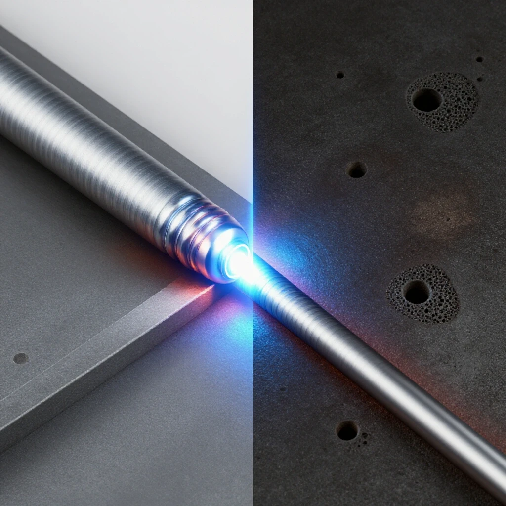
Weld porosity is characterized by small holes or pits in the weld bead, often resembling a sponge. In thick-section welding, this is usually caused by trapped gases or contaminants that cannot escape the deep “V” of the joint before the metal solidifies. It is a classic example of a hard-to-find fabrication error.
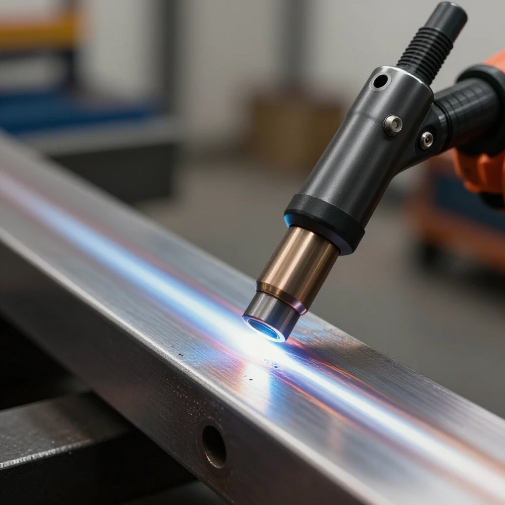
I always start my diagnosis at the gas bottle. Is the flow rate between 15 and 20 cubic feet per hour (CFH)? If it is too low, you lack coverage; if it is too high, you create turbulence that pulls in atmospheric air. I once spent three hours chasing porosity only to find a tiny pinhole in the gas hose that was sucking in air whenever the solenoid opened.
| Porosity Symptom | Potential Root Cause | Diagnostic Test |
|---|---|---|
| Uniform surface pits | Shielding gas flow too low/high | Check flowmeter and hose integrity |
| Deep internal voids | Moisture in the joint or electrode | Pre-heat metal to 250°F to drive off moisture |
| Scattered “wormholes” | Surface contaminants (oil/mill scale) | Use a clean flap disc to reach bare shiny metal |
| Intermittent clusters | Windy environment/drafts | Set up welding screens to block air movement |
Diagnosing Machine Errors and Arc Instability
Sometimes the issue isn’t your hand; it’s the machine’s heart. Electrical gremlins in a welder can manifest as a fluctuating arc, making it impossible to maintain the consistent puddle needed for a deep-section root. If the arc feels “soft” or “stuttery,” it might be a component failure within the power source.
I use a digital multimeter to check the input voltage at the wall and the output at the terminals. A common culprit in older machines is a failing bridge rectifier or a dried-out capacitor. If you notice the arc quality changes as the machine warms up, you are likely dealing with a thermal-related electrical fault. Ensure your work clamp is attached directly to the workpiece, not the table, to minimize resistance.
Mechanical Alignment and Structural Integrity
In heavy fabrication, keeping two thick plates aligned during the welding process is a mechanical challenge. If the plates warp or shift out of plane, the root pass will be uneven, leading to structural alignment faults. This requires a combination of rigid clamping and calculated pre-heating.
Managing Thermal Expansion and Warping
As you deposit molten metal into a bevel, the cooling weld pulls the tops of the plates together. This “hinge effect” can ruin the alignment of a structural component. To counteract this, I often pre-set the plates with a slight reverse “camber” or use heavy stiffeners tacked across the joint.
Monitoring temperature is vital. I use an infrared heat tracker to ensure the base metal is at a consistent pre-heat temperature, usually around 200°F to 300°F for thick carbon steel. This reduces the thermal shock and slows the cooling rate, which helps prevent hydrogen-induced cracking in the root.
Eliminating Tool Chatter and Vibrational Damage
While we often associate chatter with lathes or mills, vibrational issues can affect weld quality too. If your workpiece is not rigidly supported, the arc’s own plasma force or external shop vibrations can cause the puddle to oscillate. This results in a “rippled” root that lacks consistent fusion.
Ensure your welding table is level and the workpiece is shimmed so it cannot rock. If you are using a rotary positioner, check for spindle backlash. Even 0.005 inches of play in a gear drive can cause the part to “jump” as the weight shifts, leading to a momentary break in the arc and a defect in the root bead.
Refining the Arc: Amperage and Technique
Once the joint is prepped and the machine is verified, the execution of the first pass relies on three factors: amperage, electrode angle, and travel speed. In deep bevels, these three must be perfectly balanced to ensure the arc “washes” into both side walls while still penetrating through the bottom.
Mastering the Amperage Range
Running too cold will result in “cold lap,” where the weld sits on the surface without fusing. Running too hot will cause the root to “sink” or blow through completely. For a 1/8-inch root gap on heavy plate using a common 1/8-inch electrode, I generally stay within the 90 to 110-amp range for DC+ polarity.
- 90 Amps: Good for tight gaps or thin lands; reduces risk of burn-through.
- 100 Amps: The “sweet spot” for most 1/2-inch to 1-inch plate applications.
- 110 Amps: Necessary when the heat sink effect of the thick plate is pulling heat away too fast.
Electrode Angle and Manipulation
In a deep “V” joint, the angle of your torch or electrode determines where the heat is directed. I maintain a “drag” angle of about 5 to 10 degrees. If the angle is too steep, you will push the molten metal ahead of the arc, causing it to insulate the root and prevent penetration.
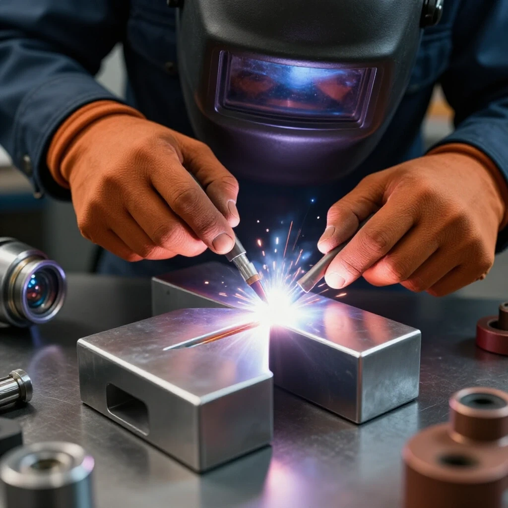
I use a slight side-to-side “wiggle” to ensure the molten puddle ties into the sharp corners of the root land. This isn’t a wide weave; it is a micro-adjustment of maybe 1/16 of an inch. The goal is to see the arc “keyhole”—a small, round hole forming at the leading edge of the puddle that indicates you are melting all the way through the joint.
Practical Tracking and Calibration Checklists
To move away from guesswork, you need to document your process. When I am troubleshooting a difficult joint, I keep a log of every variable. This allows me to look back and see exactly where a process went off the rails.
Root Pass Diagnostic Checklist
- Material Verification: Is the plate clean of mill scale and rust for at least one inch back from the bevel?
- Joint Geometry: Measure the land (target 3/32″) and the gap (target 1/8″) at three points along the joint.
- Machine Health: Check the work clamp for heat. If the clamp is hot, the connection is poor.
- Gas Flow: Verify 18 CFH at the nozzle using a portable flowmeter.
- Pre-heat: Use a Tempilstick or infrared thermometer to confirm 250°F across the weld zone.
- Tack Integrity: Ensure tacks are ground to a “feather edge” so the root pass can flow over them smoothly.
Mechanical Tolerance Standards
When working with heavy machinery or structural components, I adhere to specific tolerances to ensure the final assembly is square and true.
- Bevel Angle Tolerance: +/- 2.5 degrees.
- Root Land Consistency: +/- 0.015 inches.
- Root Gap Variation: No more than 1/32 inch over a 12-inch span.
- Maximum Warpage: 1/16 inch per foot of weld length without bracing.
Case Study: The Mystery of the Cracking Root
I once consulted for a shop that was seeing consistent cracking in the root pass of 1.5-inch thick plate. They had tried increasing the amperage and changing electrodes, but the cracks remained. It looked like a metallurgical defect, but the chemistry of the steel was fine.
By applying systematic troubleshooting, I isolated the issue to the cooling rate. Because the plates were so thick, they acted as a massive heat sink, “quenching” the small root bead almost instantly. This rapid cooling created a brittle microstructure. We solved it by increasing the pre-heat to 400°F and wrapping the joint in a welding blanket immediately after the pass. This slowed the cooling enough to prevent the cracking. It wasn’t a welding error; it was a thermal management error.
Final Inspection and Verification
The job isn’t done until you verify that the root pass has actually done its job. In a workshop environment, you may not have X-ray equipment, but there are several reliable ways to check your work.
- Visual Inspection (Back Side): If you can see the joint from the back, look for a consistent “bead” of metal protruding through. It should look like a small weld, not a series of disconnected grapes.
- Back-Grinding: On very thick plate, it is common practice to grind into the back side of the root pass until you reach clean, solid weld metal. If you see a dark line or slag trapped in the middle, you must grind it out and weld from the back.
- Dye Penetrant Testing: This is a cheap and effective way to find surface cracks or porosity. You spray a red dye on the weld, wipe it off, and apply a white developer. Any hidden cracks will “bleed” red.
Mastering these deep-section connections is a matter of discipline. It requires you to stop being just an operator and start being a technician who understands the relationship between heat, geometry, and metallurgy. When you stop guessing and start measuring, the “gremlins” in your shop tend to disappear.
Frequently Asked Questions
Why does my root pass keep burning through the metal? Burn-through usually happens because the root land is too thin or the amperage is too high. If your land is less than 1/16 inch, it cannot support the heat of the arc. Try increasing the land thickness or lowering your amperage by 5-10 amps. Also, ensure your travel speed isn’t too slow, which hangs the heat in one spot for too long.
What causes “slag inclusions” in the first bead? Slag inclusions occur when the molten glass-like coating of the electrode gets trapped inside the weld. This often happens if the bevel angle is too narrow (less than 60 degrees total), preventing the slag from floating to the top. It can also happen if you don’t clean the slag completely off your tacks before welding over them.
How do I prevent the root gap from closing up as I weld? The heat of the weld causes the metal to pull together. To prevent this, use larger, more frequent tacks. For thick plate, a tack should be at least one inch long. You can also use “dogs and wedges”—temporary mechanical clamps welded to the plate—to physically hold the gap open during the first pass.
Why is my arc jumping from side to side instead of hitting the root? This is often “arc blow,” caused by magnetic fields building up in the steel. It is common in thick plate and near the ends of joints. To fix it, try moving your work clamp to a different location, or switch to Alternating Current (AC) if your machine supports it, as AC is less susceptible to magnetism.
How can I tell if I have “cold lap” in my root? Cold lap, or lack of fusion, often looks like the weld metal is just “leaning” against the side of the bevel without blending in. If you can see a distinct line between the weld and the plate, or if you can flick a piece of the weld off with a cold chisel, you have cold lap. This is usually caused by low amperage or an incorrect electrode angle.
Is pre-heating really necessary for 1/2-inch plate? While you can often get away without it on 1/2-inch plate in a warm shop, it is highly recommended. Pre-heating to 200°F removes moisture (preventing porosity) and reduces the chance of the weld cracking by slowing the cooling rate. For anything over 3/4 inch, pre-heating should be considered mandatory.
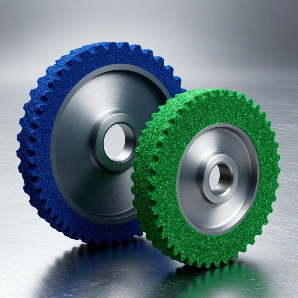
What is the best way to clean a bevel before welding? A standard grinding wheel is good for shaping the bevel, but it can leave grit behind. I always finish the surface with a clean stainless steel wire brush or a new flap disc. Avoid using a “used” disc that has been grinding aluminum or oily steel, as it will transfer those contaminants into your joint.
Can I run a root pass with MIG or is Stick better? Both can work, but they require different approaches. Stick (SMAW) is often preferred for thick plate in DIY settings because it offers deeper penetration and handles contaminants better. If using MIG (GMAW), you must ensure you are not in “short-circuit” mode, which is prone to cold lap on thick sections; use a spray-transfer setting if your machine has the power.
How do I fix a “keyhole” that is getting too large? If the keyhole starts to grow uncontrollably, you are about to blow through. Immediately increase your travel speed and tilt your electrode more toward a “push” angle to direct heat away from the root. If that doesn’t work, stop the weld, let it cool, and lower your amperage before restarting.
What is the “feathering” technique for tacks? Feathering means grinding the start and end of a tack weld until they are paper-thin. This creates a ramp that allows your main root pass to “climb” onto the tack and melt into it seamlessly. If you don’t feather your tacks, you will often end up with a lump or a cold spot where the two welds meet.
(This article was written by one of our staff writers, Paul Whitaker. Visit our Meet the Team page to learn more about the author and their expertise.)