How to Level and Square a Heavy Metal Fabrication Table (Fix)
I’ve spent thirteen years in the shop, and if there is one thing I’ve learned the hard way, it’s that your project is only as straight as the surface it’s built on. I remember a specific utility trailer build early in my career. I had measured every tube twice, cut them to the exact sixteenth of an inch, and spent hours on my weld sequencing layout. When I finally cut the trailer loose from the table and set it on the floor, one corner sat three-quarters of an inch high. The frame was twisted. The culprit wasn’t my tape measure; it was my heavy steel workbench. It looked flat to the naked eye, but it had a subtle crown that transferred directly into my chassis.
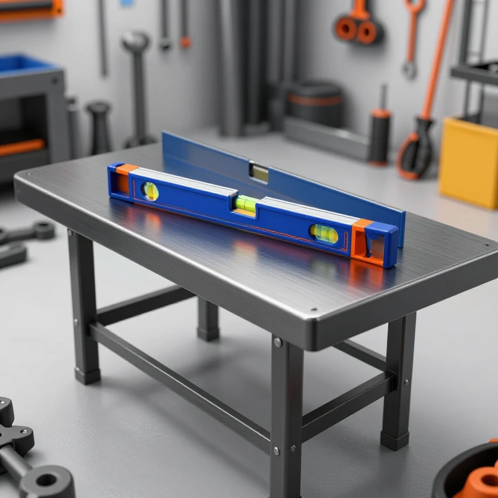
In custom fabrication projects, we often focus on the welder or the saw, but the most critical tool in the garage is the horizontal plane of your work surface. If your table isn’t true, every tack weld you make is essentially locking a mistake into your metal. This guide focuses on the manual methods I use to ensure a heavy steel work surface—typically those over 200 pounds—is properly aligned and ready for precision work. We will use basic tools like machinist levels, feeler gauges, and shims to correct existing surfaces without the need for expensive machining.
Establishing a Reference Plane for Workshop Jigs and Fixtures
A reference plane is a perfectly flat, theoretical surface that serves as the starting point for all measurements in a three-dimensional project. In a home shop, your heavy steel table acts as this plane, providing a stable base where you can trust that “level” and “square” are consistent across the entire work area.
When I talk about a work surface being “true,” I am referring to two distinct concepts: planarity and level. Planarity means the surface is flat—there are no dips, humps, or twists. Level means that this flat surface is oriented perfectly perpendicular to the pull of gravity. For most of us, having a table that is perfectly level is a luxury, but having one that is planar is a requirement. If a table has a twist, or “wind,” one corner is higher than the others relative to the center. This twist will force your metal layout tips to fail because your workpieces will never sit flush against the steel.
To begin, you need to understand that steel is not a static material. A heavy table can sag under its own weight or warp due to the heat of previous projects. Before we start adjusting, we must clear the surface of all slag, rust, and weld spatter. I use a wide, flat file or a heavy scraper to ensure I’m measuring the steel itself, not the debris on top of it.
Measuring Surface Deviations with Machinist Tools
Measuring surface deviations involves using precision instruments to identify exactly where a work surface departs from a perfectly flat plane. By using a high-quality straightedge and feeler gauges, you can quantify the gaps in your table down to the thousandth of an inch.
I start by using a precision straightedge, ideally one at least 48 inches long. I lay it across the table in a “star” pattern: horizontally, vertically, and diagonally from corner to corner. Where light shines under the straightedge, there is a low spot. I use feeler gauges—thin strips of metal of known thicknesses—to measure these gaps. If I can slide a 0.010-inch gauge under the straightedge, I know exactly how much correction that area needs.
| Measurement Tool | Purpose in Alignment | Target Tolerance |
|---|---|---|
| Machinist Level | Checking for twist across the length | +/- 0.005″ per foot |
| Precision Straightedge | Identifying local high and low spots | +/- 0.010″ over 4 feet |
| Feeler Gauges | Quantifying the depth of surface dips | 0.002″ to 0.030″ range |
| Try Square | Checking verticality of side plates | 90 degrees (+/- 0.5) |
For heavy tables, I also rely on a machinist level. Unlike a standard carpenter’s level, a machinist level is sensitive enough to show a deviation of just a few thousandths of an inch over a foot. I place the level at one end of the table and then move it to the other, looking for a change in the bubble’s position. If the bubble moves, the table has a twist that must be corrected by adjusting the legs.
Correcting Table Twist through Iterative Shimming
Shimming is the process of placing thin spacers under the legs of a table or between the frame and the tabletop to eliminate wobble and twist. This is an iterative process, meaning you make a small change, re-measure, and then adjust again until the surface meets your required tolerance.
If you have a heavy table with four legs, it is almost guaranteed that your floor is not perfectly flat. This causes the table to “tripod” or twist the tabletop as the weight settles. To fix this manually, I focus on the diagonal measurements. If the straightedge shows a gap on the front-left to back-right diagonal, I know I need to raise one of those corners.
I prefer using steel shim stock, which comes in various thicknesses from 0.001 to 0.025 inches. If your table has adjustable leveling feet, the process is easier, but for fixed-leg tables, you will be sliding these shims under the feet.
- Identify the lowest corner using the machinist level.
- Place a 0.010-inch shim under that leg.
- Re-check the diagonals with the straightedge and feeler gauges.
- If the gap decreases but remains, add another shim.
- If the gap moves to the opposite diagonal, you have shimmed too far.
Interestingly, even a 300-pound table can flex. When you add a shim to one corner, it doesn’t just raise that corner; it changes the tension across the entire top. This is why you must check the center of the table after every adjustment to ensure you aren’t creating a “hump” by over-correcting the corners.
Squaring the Perimeter for Accurate Square Cuts
Squaring a table involves ensuring that the edges and any integrated grid lines are perfectly perpendicular to one another. This allows you to use the table edges as a giant square, making it much easier to align large frames or custom fabrication projects.
Once the table is flat, I turn my attention to the perimeter. Most DIY tables are made of rectangular tubing or channel. I use the 3-4-5 triangle method to verify the squareness of the corners. By measuring 3 feet along one side and 4 feet along the adjacent side, the diagonal distance between those two points must be exactly 5 feet. If it’s 5 feet and 1/16th of an inch, the corner is “open” and needs to be addressed.
For tables with a thick plate top, you can manually file the edges to bring them into square, though this is labor-intensive. A more practical approach for the garage builder is to establish “zero lines” using a scribe. I use a large framing square to mark lines exactly 90 degrees to each other on the table surface. These lines become my guide for setting up workshop jigs and fixtures. When I align a piece of tubing to these scribed lines, I know it is square regardless of whether the physical edge of the table is slightly off.
Managing Heat Distortion and Weld Sequencing Layout
Weld shrinkage is the physical contraction of metal as it cools from a molten state to room temperature. This force is powerful enough to bend heavy steel plate, meaning that even a perfectly aligned table can be pulled out of shape if you weld directly onto it without a plan.
When you are building on your newly leveled surface, you must account for angular weld shrinkage. As a weld bead cools, it pulls the two pieces of metal toward the side where the weld was placed. If you weld only on the top side of a joint, the heat will pull the ends of your project upward, away from your flat table.
To combat this, I use a specific weld sequencing layout. I never finish a weld in one go. Instead, I place small, strong tack welds at all four corners of a joint. I then move around the project, welding in short bursts on opposite sides. This balances the “pull” of the cooling metal.
| Joint Type | Typical Angular Shrinkage | Recommended Tack Spacing |
|---|---|---|
| T-Joint (Fillet) | 1 to 3 degrees | Every 4 to 6 inches |
| Butt Weld | 0.030″ to 0.060″ width loss | Every 3 inches |
| Outside Corner | 2 to 4 degrees | Every 2 inches |
I also use the table itself as a heat sink. By clamping my workpieces firmly to the heavy steel top, the table absorbs some of the heat and physically restrains the metal from moving. However, be careful: if the table top is thin (less than 1/2 inch), the heat from a large project can actually warp the table itself. For heavy projects, I use “riser blocks”—small, identical pieces of scrap square tubing—to hold the project 1 or 2 inches off the table. This allows air to circulate and prevents the table from soaking up too much concentrated heat.
Practical Metal Layout Tips for Maintaining Tolerances
Maintaining tight dimensional tolerances requires a combination of accurate marking, smart cutting, and constant verification. In my shop, “close enough” usually results in a project that requires a sledgehammer to assemble, so I aim for a tolerance of +/- 1/16th of an inch over a 10-foot span.
One of the biggest mistakes I see is failing to account for the kerf. The kerf is the width of the material removed by the cutting tool. If you use a chop saw with a 1/8-inch thick blade and you cut on the “wrong” side of your mark, your part will be 1/8-inch too short.
- Always mark your cut with a thin soapstone or a scribe for better precision than a thick carpenter’s pencil.
- Mark which side of the line is the “waste” side.
- Measure your parts after cutting but before welding. It is much easier to grind 1/16th off a tube than it is to fix a twisted frame later.
- Use a “story pole”—a single piece of scrap metal where you mark all your major dimensions. Use this pole to check all repeating parts for consistency.
When laying out a frame on your table, always measure the diagonals of the frame itself. Even if your table is square, your project might not be. If the two diagonal measurements of a rectangular frame are within 1/16th of an inch of each other, the frame is square. If they differ by 1/4 inch, you need to use a pipe clamp to pull the long diagonal into alignment before you finish welding.
Final Alignment Checks and Maintenance Logs
A heavy fabrication table is a living tool. Because of the weight it carries and the heat it endures, it will shift over time. I keep a simple maintenance log hanging on the wall near my welding station. Every six months, or after a particularly heavy project, I spend thirty minutes re-checking the planarity.
This doesn’t have to be a chore. I simply repeat the “star” pattern check with my straightedge. If I notice that a certain area has developed a dip, I check the shims under the legs. Often, the vibrations from grinding and the weight of the steel have compressed the shims or caused the table to settle into the concrete floor.
By keeping a log of these checks, you can see patterns. If the back-right corner is always sinking, you might have a thin spot in your concrete floor or a moisture issue. Addressing these small problems early prevents them from ruining a major build.
Common Pitfalls in Manual Table Adjustment
One of the most common mistakes I see in garage shops is over-tightening the bolts that hold a tabletop to its frame. If you have a 1-inch thick plate bolted to a frame made of 2-inch tubing, and you tighten those bolts as hard as possible, any slight twist in the frame will be forced into the plate. I prefer to let the plate “float” slightly or use adjustable spacers between the frame and the top. This allows the heavy plate to find its own natural flat state.
Another pitfall is ignoring the temperature. Steel expands when it’s hot. If you level your table in the middle of a hot summer afternoon and then check it on a freezing winter morning, you might see a difference of several thousandths of an inch. While this might not matter for a gate or a trailer, it matters for precision fixtures. Try to perform your final alignment checks at a consistent shop temperature.
Finally, don’t rely on “eye-balling” it. The human eye is incredibly good at seeing straight lines, but it is terrible at judging flat planes over a large area. I’ve seen builders swear a table was flat, only to find a 1/8-inch dip when the straightedge was applied. Trust your tools, not your eyes.
Actionable Steps for Your Next Weekend Build
If you are planning to build a project soon, take these three steps this weekend to prepare your work surface:
- The Clean Sweep: Use a flap disc or a hand file to remove every bit of weld spatter from your table. A single 0.020-inch bead of spatter can throw off a level reading.
- The Diagonal Test: Take a long piece of straight square tubing and lay it across the diagonals of your table. Use a flashlight behind the tube; if you see light peeking through in the middle, your table is “dished.”
- The Shim Fix: Purchase a pack of assorted brass or steel shims. Lift each leg of your table and ensure it is making firm contact with the floor. If you can rock the table even a tiny bit, it is not stable enough for precision work.
Building something with your own hands is rewarding, but building something that is straight, square, and true is a different level of satisfaction. It starts with the table. If you put in the work to align your foundation, the rest of the build will follow suit with much less frustration.
Frequently Asked Questions
How flat does a fabrication table really need to be? For most DIY projects like trailers, furniture, and carts, a tolerance of +/- 1/32 of an inch across the entire surface is excellent. If you are building precision engine mounts or suspension components, you should aim for +/- 0.010 inches.
Can I use a digital level instead of a machinist level? Digital levels are convenient, but most consumer-grade models are only accurate to 0.1 degrees. A machinist level is significantly more sensitive. For structural flatness, a precision bubble level or a long straightedge with feeler gauges is usually more reliable than a cheap digital sensor.
What if my steel plate is permanently bowed from the mill? Most hot-rolled steel plate has some mill scale and a slight natural bow. If the bow is significant, you can try to “draw” it flat by welding stiffeners to the underside, but this is advanced work. For most, shimming between the table frame and the plate is the most effective manual fix.
Should I weld my tabletop to the frame or bolt it? Bolting is generally better for maintaining flatness. It allows you to use shims between the frame and the top to correct for any deviations. Welding the top can introduce heat distortion that is very difficult to remove without professional machining.
How do I stop my table from moving when I’m hammering on it? Mass is your friend. If your table is under 200 pounds, consider adding a lower shelf and loading it with heavy off-cuts or sandbags. A stable table is essential for accurate measurements.
Does the thickness of the tabletop matter for alignment? Yes. A 1/4-inch top will warp much more easily under weld heat than a 1/2-inch or 3/4-inch top. Thicker tops are harder to move initially but stay true much longer.
What is the best way to check for a “twist” in a rectangular table? The “winding sticks” method works well. Place two perfectly identical straightedges at opposite ends of the table. Sight across the top of one to the other. If the edges aren’t parallel to your eye, the table has a twist.
Can I use wood shims for my metal table? No. Wood shims will compress over time under the weight of the steel and the vibrations of the shop. Always use metal shims (steel, brass, or aluminum) for a permanent, stable alignment.
How often should I re-verify the squareness of my table? I recommend checking it before starting any major project where dimensions are critical. For general shop use, a quick check every six months is usually enough to catch any settling or movement.
What is the most common cause of a table going out of square? Uneven floor settling is the primary cause. Concrete floors often crack or sink slightly over time, especially under the weight of a heavy fabrication table and the materials stored on it.
(This article was written by one of our staff writers, Robert Kline. Visit our Meet the Team page to learn more about the author and their expertise.)