How to Write Steel Project Cut Sheets to Reduce Scrap (Fix)
Managing a shop that has outgrown its hobbyist roots is a unique challenge. In my 20 years of operating a fabrication space, I have learned that the transition from “making things” to “manufacturing products” is often won or lost in the trash bin. When I first started, I would walk up to a rack, grab a stick of tube or a sheet of plate, and start cutting based on a rough measurement. As my volume increased, that lack of a plan led to a mountain of expensive steel scrap and a shop floor that felt like an obstacle course.
The stress of scaling isn’t just about finding more customers. It is about the physical and financial weight of inefficiency. If you are moving 4×8 sheets of 1/4-inch plate by hand across a cluttered floor, you are losing money. If your cut lists don’t account for the width of the blade or the torch, your last part will be short, and you will have to break into a fresh sheet. This guide focuses on the systematic planning required to turn raw steel into finished parts with as little waste as possible.
Mapping Material-Flow Loops for Better Yield
A material-flow loop is the physical path steel takes from the moment it enters your shop until it leaves as a finished part. An efficient loop minimizes the number of times you touch a piece of metal, which reduces labor costs and the risk of material damage.
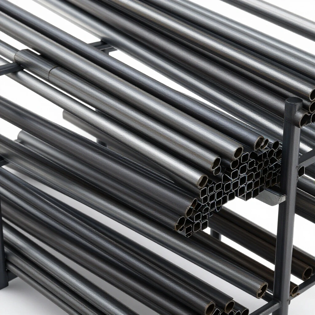
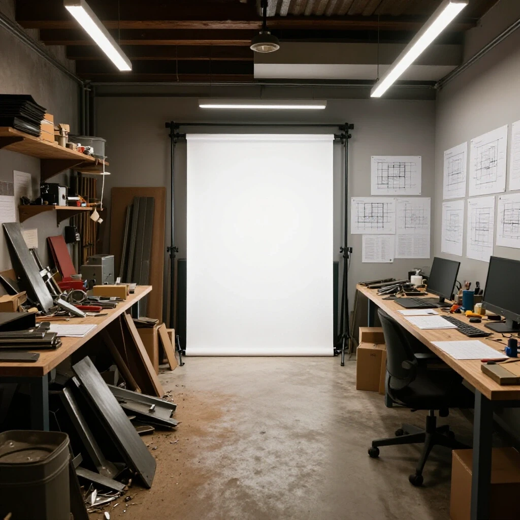
In my early days, my material rack was at the back of the shop, but my primary saw was near the front door. I spent half my day playing a dangerous game of Tetris with 20-foot sticks of tubing. When I finally sat down to map my floor layout, I realized I was walking miles every week just to move material. I reorganized the shop into a “U” shaped flow. Material comes in one door, sits in a rack next to the primary cutting station, moves to the CNC or manual layout table, and then proceeds to the assembly area.
| Layout Type | Material Travel Distance | Handling Time | Scrap Risk |
|---|---|---|---|
| Random Placement | High | 45% of shift | High (damage/loss) |
| Functional Grouping | Moderate | 25% of shift | Moderate |
| Linear/U-Flow | Low | 10% of shift | Low (controlled) |
To optimize this, you must understand your floor load ratings. Standard 4-inch residential garage slabs may crack under the concentrated weight of a vertical steel rack holding several tons of plate. I recommend a minimum of 6 inches of reinforced concrete for heavy material zones. This stability allows you to use taller racks, freeing up floor space for better machine access.
Balancing Power Loads for Consistent Cutting Quality
Electrical infrastructure is the heartbeat of a high-output shop. When you transition to industrial-grade cutting equipment, the demand on your electrical service changes from intermittent to constant and heavy.
Most residential or light commercial shops struggle with the lack of native 3-phase power. I solved this in my own shop using a rotary phase converter. A rotary converter uses a 3-phase motor (an idler) to generate the third leg of power. This is crucial for steel cutting because voltage drops during a heavy cut can cause a plasma torch to stutter or a saw to bind. If the cut quality is poor, you end up grinding away your profit or scrapping the part entirely.
When setting up your power, aim for a phase balance within 5% to 10%. If one leg of your power is significantly lower than the others, your motors will run hot and lose torque. I keep a digital multimeter near my main panel to check these loads during peak operation. This ensures that when I am executing a complex cut plan, the machine performs exactly as expected every time.
Designing High-Volume Air Filtration for Metal Particulates
Clean air is not just about comfort; it is about machine longevity and part accuracy. Fine steel dust and plasma dross are abrasive and conductive. If they settle on your precision rails or inside your control cabinets, they will cause mechanical drift.
A professional-grade dust collection system should be designed around static pressure and CFM (Cubic Feet per Minute). For a standard 4×4 or 4×8 cutting station, you want a minimum of 1,000 to 1,500 CFM at the source. I use a multi-stage cyclone separator. The cyclone drops the heavy chips and dross into a bin before the fine dust reaches the filters. This prevents the filters from clogging every few hours, which would otherwise drop your suction and leave the shop in a haze.
- Ducting Tip: Use smooth-walled metal ducting instead of flexible ribbed hose. The ribs in flexible hoses create turbulence and static pressure loss, which can kill the efficiency of your blower.
- Filter Metric: Look for filters rated for sub-micron particles. Steel dust from high-speed cutting is incredibly fine and can bypass standard shop-vac filters easily.
Strategic Part Nesting and Dimensioning for Maximum Yield
The core of reducing waste is the strategic arrangement of parts on a raw piece of steel. This starts with accurate dimensioning from your project drawings. You cannot plan a cut sheet if your measurements are “close enough.”
One of the biggest mistakes I see experienced fabricators make is ignoring the kerf. The kerf is the width of the material removed by the cutting process. If you are using a cold saw with a 1/8-inch blade and you need ten 12-inch pieces, you cannot get them out of a 120-inch stick of steel. You will be 1-1/4 inches short because of the ten cuts you made.
| Cutting Method | Typical Kerf Width | Cleanup Allowance |
|---|---|---|
| Band Saw | 0.035″ – 0.050″ | Minimal |
| Cold Saw | 0.090″ – 0.125″ | None (Finished) |
| Plasma (Hand) | 0.060″ – 0.100″ | 0.125″ (Grinding) |
| CNC Plasma | 0.040″ – 0.080″ | 0.060″ (Light Sanding) |
When I write a cut sheet, I account for the kerf plus a “cleanup allowance.” If a part needs to be exactly 24 inches after I grind off the heat-affected zone from a plasma cut, I plan for 24-1/8 inches. By documenting these allowances in a standardized format, you ensure that the person at the saw knows exactly where to pull the tape.
Building a Remnant Management System to Capture Value
A common bottleneck in scaling shops is the “remnant pile.” These are the offcuts that are too big to throw away but too small to have a designated home. Without a system, you will find yourself buying a new 20-foot stick of 2×2 square tube because you couldn’t find the 4-foot piece buried under a pile of scrap.
I implement a strict “Remnant First” policy. Every offcut over 12 inches is labeled with its material type, thickness, and length using a paint marker. These pieces are stored in a specific rack, organized by shape (flat bar, angle, tube). When I start a new project, the first step is to check the remnant log.
- Identify the largest parts first: Always place your biggest components on the fresh sheets or full sticks.
- Fill the gaps: Use the “holes” left in the layout for smaller brackets or gussets.
- Sequence the cuts: Cut the parts in an order that leaves the largest possible rectangular or linear remnant. A long, skinny strip of plate is often more useful than a series of small triangles.
- Log the leftovers: Immediately measure and mark the remaining material before it hits the rack.
Critical Benchmarks for Workshop Efficiency
To move from a hobby mindset to a professional one, you need to track your performance. I use a few simple metrics to see if my layout and planning are actually working.
- Material Utilization Rate: Aim for 85% or higher. This means only 15% of the steel you buy ends up as unusable scrap.
- Machine Access Zone: Maintain a 3-foot minimum clearance around all major equipment. This prevents bottlenecks when moving long material.
- Electrical Phase Balance: Check your 3-phase legs every month. A deviation of more than 10% indicates a problem with your converter or a failing motor.
- Airflow Maintenance: Clean your primary dust filters every 20 hours of cutting time to maintain rated CFM.
By focusing on these structural and planning elements, you create an environment where high-efficiency cutting is the path of least resistance. It takes more time upfront to write a detailed cut sheet and organize a remnant rack, but the reduction in wasted material and “re-work” time is where your shop’s growth is funded.
Frequently Asked Questions
How do I calculate the kerf for a tool I’ve never used before? The most reliable way is to perform a test cut. Take a piece of scrap and measure its width with calipers. Make a single cut, then measure the width of the remaining piece. The difference between the original width and the sum of the two pieces is your kerf. Do this three times and take the average.
Why does grain direction matter in steel plate? While steel is generally isotropic, the rolling process at the mill can create a subtle grain. For most structural parts, it doesn’t matter. However, if you are performing heavy bends, bending “with the grain” (parallel to the rolling direction) can sometimes lead to cracking. Planning your cut sheet to align bends perpendicular to the grain is a professional best practice.
What is the best way to store large steel plates to prevent warping? Store them vertically in a toast-rack style holder if possible. If you must store them flat, ensure the floor is perfectly level and use enough “stickers” (spacers) to prevent the plate from sagging under its own weight. A warped plate will never sit flat on a cutting table, leading to inaccurate dimensions.
How do I handle “tolerance stack-up” on a long cut list? Tolerance stack-up happens when small errors in each cut add up to a large error at the end. To fix this, always measure each piece from the same “zero” point on the material rather than measuring from the previous cut. This ensures that a 1/16-inch error on one part doesn’t move every subsequent part further out of spec.
Should I use a software-based nesting tool or do it manually? For complex shapes on plate, software is almost always better at finding the tightest fit. For linear material like tubing and angle iron, a manual cut sheet is often faster and just as effective, provided you remember to account for the blade kerf.
What is the most common mistake in shop layout for steel fabrication? The most common mistake is not leaving enough room for the “outfeed.” People often plan for the space the machine takes up, but forget that a 20-foot stick of steel coming out of a saw needs another 20 feet of clear space on the other side.
How do I know if my dust collection is actually working? You can use a simple pitot tube or an anemometer to check the air velocity in your ducts. For steel dust, you want a “transport velocity” of about 3,500 to 4,000 feet per minute (FPM) to keep the heavy particles moving through the pipe so they don’t settle and clog the system.
Can I run a CNC plasma table on a rotary phase converter? Yes, but you must be careful. Some CNC electronics are sensitive to the “manufactured leg” of a rotary converter, which can have slightly different voltage characteristics. It is often best to run the sensitive control electronics on a stable 110v or 220v single-phase circuit and use the 3-phase power only for the high-draw motors or the plasma power supply itself.
(This article was written by one of our staff writers, Edward Sinclair. Visit our Meet the Team page to learn more about the author and their expertise.)