Scheduling Calendars for Custom Projects (DIY Checklist)
Scaling a workshop from a weekend hobby space to a high-output fabrication environment is a transition filled with both excitement and legitimate frustration. I have spent over 20 years refining my own shop floor, moving from a basic welder and a hand-held grinder to a fully integrated CNC plasma system and professional-grade material handling. The stress of scaling does not just come from the cost of the machines; it comes from the realization that your old ways of working—tripping over cords and “eyeballing” your project timelines—no longer support the complexity of advanced fabrication. When you begin managing multiple custom builds, the bottleneck is rarely your skill with a torch. Instead, it is almost always a lack of systematic flow and a failure to sequence tasks in a way that keeps the machines running and the floor clear.

Mapping the Material-Flow Loop to Minimize Foot Traffic
A material-flow loop is the physical path raw stock takes from the moment it enters your shop until it leaves as a finished product. In an optimized layout, this path should be as linear or circular as possible to prevent “backtracking,” which is when you move a part backward through the shop to reach a tool you already passed.
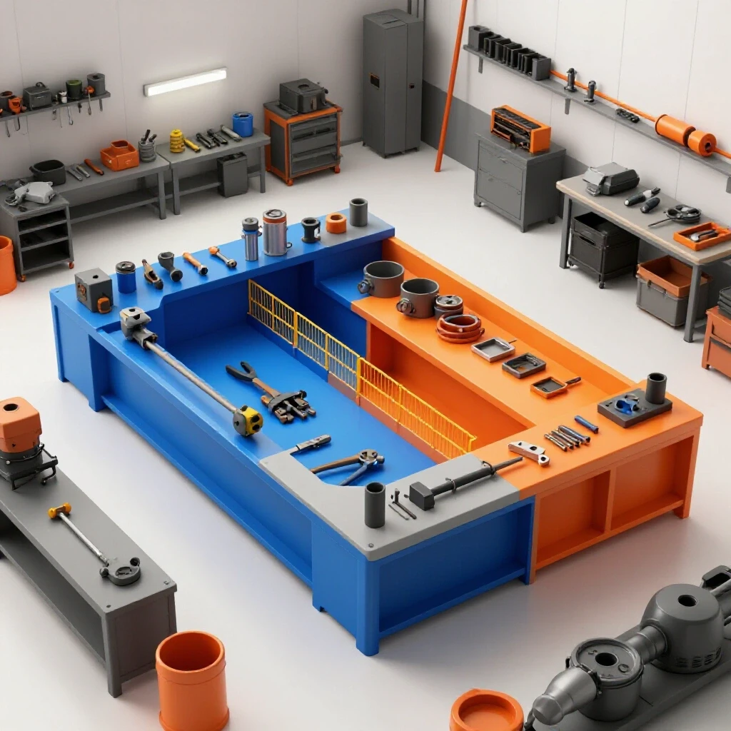
Early in my career, I placed my horizontal bandsaw in the far back corner because that was the only spot with an open outlet. Every time I needed to cut a 20-foot stick of tubing, I had to clear a path through the entire shop, only to carry the cut pieces back to the front for welding. This wasted thirty minutes a day in foot traffic alone. Now, I organize my shop into “activity zones.” The “Dirty Zone” for cutting and grinding stays near the large roll-up door. The “Precision Zone” for CNC work and assembly sits in the center, and the “Clean Zone” for finishing and electrical work is tucked away from the metal dust.
| Layout Style | Material Travel | Bottleneck Risk | Best Use Case |
|---|---|---|---|
| Random Placement | High (Erratic) | Very High | Small hobby repairs |
| Perimeter Loading | Medium | High (Center Clutter) | Low-volume assembly |
| U-Shaped Flow | Low | Medium | Single-operator shops |
| Linear Production | Minimal | Low | High-output fabrication |
To fix your flow, take a piece of graph paper and draw your shop. Trace the path of a single project from raw steel to the paint booth. If your lines look like a bowl of spaghetti, you are losing money on every step you take. Aim for a 3-foot minimum access zone around every major stationary tool to ensure you can move workpieces without performing a balancing act.
Scaling Power with 3-Phase Converters for Heavy Machinery
Three-phase power is a standard in industrial manufacturing that provides three alternating currents to a machine, allowing for smaller motors to produce more torque and run more efficiently than single-phase versions. Most home-based shops only have 240V single-phase power, which limits the type of professional surplus machinery you can buy and operate.
When I bought my first industrial ironworker, I was faced with a choice: pay the utility company thousands to run a new line or install a converter. For the advanced shop owner, a Rotary Phase Converter (RPC) or a Variable Frequency Drive (VFD) is the bridge to professional capability. A VFD is excellent for a single machine, like a lathe or mill, because it allows for speed control. However, if you plan to run a CNC plasma table, a compressor, and a mill simultaneously, a high-quality RPC is a more robust heart for your electrical system.
- Rotary Phase Converters (RPC): These use a generator motor to create the third leg of power. They are reliable and can power multiple machines at once.
- Variable Frequency Drives (VFD): These are solid-state devices. They are perfect for motor speed control but are usually dedicated to one specific machine.
- Static Converters: I generally advise against these for high-output shops. They only start the motor and then drop back to two legs, reducing your machine’s horsepower by about one-third.
Before you buy a converter, calculate your Total Connected Load. Look at the Full Load Amps (FLA) on your machine tags. If you are running a CNC system, ensure your phase converter is “CNC rated,” meaning the voltage balance between the three legs is within 2% to 5% to avoid frying sensitive electronics.
Designing High-Volume Air Filtration and Fume Extraction
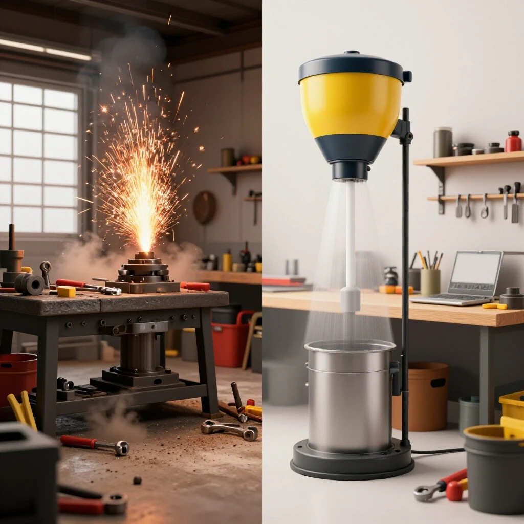
Air quality management is the process of capturing airborne particulates and hazardous gases at the source before they enter the operator’s breathing zone. In a shop with a CNC plasma table or heavy welding, you are dealing with sub-micron dust that can settle on everything and damage your lungs and your machinery’s lead screws.
I learned the hard way that a single shop vac or a standard ceiling fan is not a ventilation strategy. For a 1,000-square-foot shop, you need to look at Cubic Feet per Minute (CFM) ratings. A CNC plasma table typically requires a dedicated exhaust fan pulling at least 1,000 to 2,000 CFM or a water table to trap dross. If you are building a duct network for a wood-metal hybrid shop, you must account for “static pressure loss.” This is the resistance the air faces as it moves through pipes and elbows.
- Use smooth-walled metal ducting instead of flexible ribbed hoses to reduce friction.
- Keep duct runs as short and straight as possible.
- Install a multi-stage cyclone separator to drop large chips before they hit your fine filters.
- Ensure you have “make-up air.” If you suck 2,000 CFM out of a sealed shop, you need a way for 2,000 CFM of fresh air to get back in, or your fans will struggle and stall.
Integrating CNC Plasma Systems into the Workshop Workflow
CNC plasma integration is the transition from manual cutting to automated, computer-controlled precision. This involves setting up a gantry system, a plasma power source, and a software chain that converts a drawing into a toolpath. It is the single biggest jump in productivity an advanced shop can make.
The learning curve is steep. You aren’t just learning a tool; you are learning a digital process. When I integrated my first 4×8 table, I spent the first month failing because my air wasn’t dry enough. Moisture in your air lines will eat through plasma consumables and ruin your cut quality. You need a dedicated refrigerated air dryer or a multi-stage desiccant system.
- Stepper Motors vs. Servo Motors: Steppers are affordable and precise but can “lose their place” if the torch hits an obstacle. Servos use encoders to tell the computer exactly where they are, providing higher speeds and more reliability for professional work.
- Water Tables vs. Down-Draft: Water tables are easier to maintain in a home shop and do a great job of catching dust. Down-draft tables require massive fans but keep the parts dry and easier to handle immediately after cutting.
- Gantry Leveling: Your table must be perfectly level and square. If the gantry is out of alignment by even a fraction of an inch, your holes will be oval and your parts won’t fit during assembly.
Establishing a Project Sequencing Framework for Custom Builds
A project sequencing framework is a logical order of operations used to move a build through different stages of fabrication without creating a logjam. It ensures that you aren’t trying to weld a part that hasn’t been deburred yet, or realizing you forgot to cut a bracket when the CNC table is already set up for a different material.
In my shop, I use a physical “Phase-Based Checklist” for every custom build. This keeps the workflow predictable. If I am building a custom bumper, I don’t just start cutting. I follow a sequence: Digital Design, Material Nesting, CNC Cutting, Slag Removal, Folding/Bending, Tack Welding, Final Welding, and Finishing. By treating every project like a series of repeatable steps, I can estimate my time accurately.
- Stage 1: The Digital Foundation. Finalize your CAD drawings before the first spark flies. Verify all dimensions and material thicknesses.
- Stage 2: Material Preparation. Group all parts by material gauge. Cut all your 3/16″ parts at once to minimize nozzle changes on the plasma cutter.
- Stage 3: The Assembly Sequence. Determine which parts need to be welded first to allow access for interior welds. This prevents “welding yourself into a corner.”
- Stage 4: Quality Control Checkpoints. Inspect your fit-up before final welding. It is much easier to fix a tack weld than a full penetration bead.
Using a simple whiteboard or a digital spreadsheet to track where each project sits in this sequence prevents the “mental load” of trying to remember everything. When you can see that Project A is in the “Welding” phase and Project B is in the “Cutting” phase, you can manage your shop floor much more effectively.
Optimizing the CAD/CAM Path for Rapid Prototyping
The CAD/CAM path is the digital bridge between your design software (Computer-Aided Design) and the machine’s instructions (Computer-Aided Manufacturing). For advanced fabricators, this path must be streamlined to reduce the “office time” that keeps you away from the torch.
I recommend standardizing your “Tooling Files.” In your CAM software, create presets for every material you commonly cut. For example, have a “10-gauge Mild Steel” profile that already has the correct feed rate, pierce delay, and cut height saved. This eliminates the guesswork and the wasted material of “test cuts.”
- CAD (Design): Use software that allows for parametric modeling. If you change the width of a bracket, the hole locations should update automatically.
- CAM (Toolpath): Use nesting features to fit as many parts as possible on a single sheet of steel. This reduces material waste and saves money.
- Post-Processor: This is the translator that turns the design into G-code for your specific CNC controller. Make sure your post-processor is dialed in to handle “lead-ins” and “lead-outs” so you don’t leave divots in your finished parts.
| Task Category | Tool/Software Type | Primary Goal |
|---|---|---|
| Design | Fusion 360 / SolidWorks | Precise 3D Geometry |
| Nesting | SheetCam / Pronest | Material Efficiency |
| Machine Control | Mach4 / LinuxCNC | G-Code Execution |
| Air Management | Static Pressure Calc | Fume Extraction Efficiency |
Implementing a Maintenance Routine for Shop Longevity
A maintenance routine is a scheduled set of inspections and cleanings designed to prevent machine downtime. In a high-output shop, a broken machine isn’t just an annoyance; it stops the entire sequencing of your projects.
I keep a logbook for my CNC table and my 3-phase converter. Every Monday morning, I spend 30 minutes on “Shop Readiness.” I drain the air compressor tanks, wipe down the CNC rails with a light oil, and check the tension on the drive belts. This prevents the “emergency repairs” that always seem to happen right when a project is due.
- Daily: Clean the torch nozzle, drain water traps, and clear the metal dust from the welding area.
- Weekly: Check coolant levels in the bandsaw, vacuum out the electrical cabinets, and inspect cables for fraying.
- Monthly: Grease all linear bearings, check the balance on your 3-phase converter, and replace the intake filters on your air scrubbers.
Transitioning to a Semi-Professional Production Mindset
Moving from a hobbyist to an advanced fabricator is less about the tools you own and more about how you manage the space and time those tools occupy. When you focus on layout physics, electrical capacity, and task sequencing, you stop fighting your shop and start working with it.
The most important step you can take today is to stop seeing your shop as a collection of tools and start seeing it as a single, integrated machine. Every foot of travel, every amp of power, and every cubic foot of air is a component of that machine. By refining these systems, you reduce the physical and mental friction of fabrication, allowing you to focus on the craft itself rather than the chaos of the environment.
FAQ
How do I determine if my shop floor can handle the weight of new machinery? Most residential garage slabs are 4 inches thick, which can support roughly 3,000 to 4,000 PSI. This is generally enough for most light-to-medium CNC tables and mills. However, if you are installing a heavy industrial press or a large ironworker, you should check for cracks and consider a reinforced “pad” or a steel spreader plate to distribute the load over a larger surface area.
What is the most common mistake when setting up a CNC plasma table? The most frequent error is inadequate air preparation. If your air lines have moisture or oil, your cut quality will be poor, and your consumables will burn out in minutes. A simple filter is not enough; you need a dedicated refrigerated air dryer or a high-quality desiccant system to ensure the air hitting the torch is bone-dry.
How much space should I leave between my welding bench and my CNC table? You should maintain at least 5 to 8 feet of separation if possible, or use a welding screen. Grinding dust and welding sparks are the enemies of CNC electronics and precision rails. If space is tight, ensure your CNC gantry is covered or protected when you are doing heavy manual fabrication nearby.
Do I really need 3-phase power for a small fabrication shop? You don’t “need” it for basic tools, but it opens the door to high-quality industrial machinery that is often cheaper on the used market than single-phase hobbyist tools. 3-phase motors are more efficient, run cooler, and last longer. If you plan to scale up, a rotary phase converter is a very wise investment.
How do I calculate the CFM I need for my dust collection? A general rule for metalworking is to aim for a “capture velocity” at the source. For a CNC plasma table, you typically need between 150 and 250 linear feet per minute across the surface of the table. For a 4×8 table, this usually translates to a fan capable of pulling 2,000+ CFM through your ductwork.
What is the best way to organize a task checklist for a complex build? Break the build down into “logical buckets”: Design, Prep, Fabrication, and Finish. Within each bucket, list the tasks in the order they must occur. For example, you cannot “Fit-up” until you have “Deburred.” Use a physical checklist on a clipboard for each project to track progress and ensure no steps are skipped.
Why is my rotary phase converter making a loud humming noise? A slight hum is normal, but a loud or vibrating noise usually indicates an imbalance in the capacitor banks or a mounting issue. Ensure the converter is bolted to a solid surface with vibration isolation pads. If the noise persists, check the voltage balance between the legs; an imbalance can cause the motor to work harder than necessary.
How often should I replace the filters in my shop’s air scrubber? In a high-production environment, pre-filters should be checked weekly and replaced monthly. The main HEPA or charcoal filters can last 6 to 12 months depending on the volume of fumes. If you start to see a “haze” in the shop lights or smell metal dust, your filters are likely bypassed or saturated.
Can I run my CNC table and my welder off the same sub-panel? Yes, provided the sub-panel has enough total amperage. However, CNC controllers are sensitive to “electrical noise.” It is best practice to have the CNC on a surge-protected circuit and ensure your welder is properly grounded to prevent high-frequency interference from crashing your computer mid-cut.
What is “static pressure” in a duct system? Static pressure is the resistance to airflow caused by friction against the duct walls and turbulence in bends. The more elbows and long runs you have, the higher the static pressure. You need a fan with a “fan curve” that can maintain your required CFM even when fighting the resistance of your specific duct layout.
(This article was written by one of our staff writers, Edward Sinclair. Visit our Meet the Team page to learn more about the author and their expertise.)