How to Set Your MIG Welder Voltage for Thin Sheet (Tutorial)
In my 14 years of inspecting industrial steel and managing shop floor fabrication, I have seen that the most common failures often occur on the smallest scales. While heavy structural beams demand massive heat and deep penetration, working with thin sheet metal between 0.5 mm and 2 mm requires a much more delicate balance of physics and electrical settings. I remember a specific project early in my career involving a lightweight aluminum enclosure where the fabricator underestimated the relationship between voltage and travel speed. The result was a series of “grapes” on the surface and a complete lack of fusion underneath, leading to a structural failure during a basic vibration test. These experiences taught me that managing the arc on thin materials is not about raw power, but about controlling the energy density to prevent warping and burn-through.
The Physics of Short-Circuit Transfer in Thin Sheet Fabrication
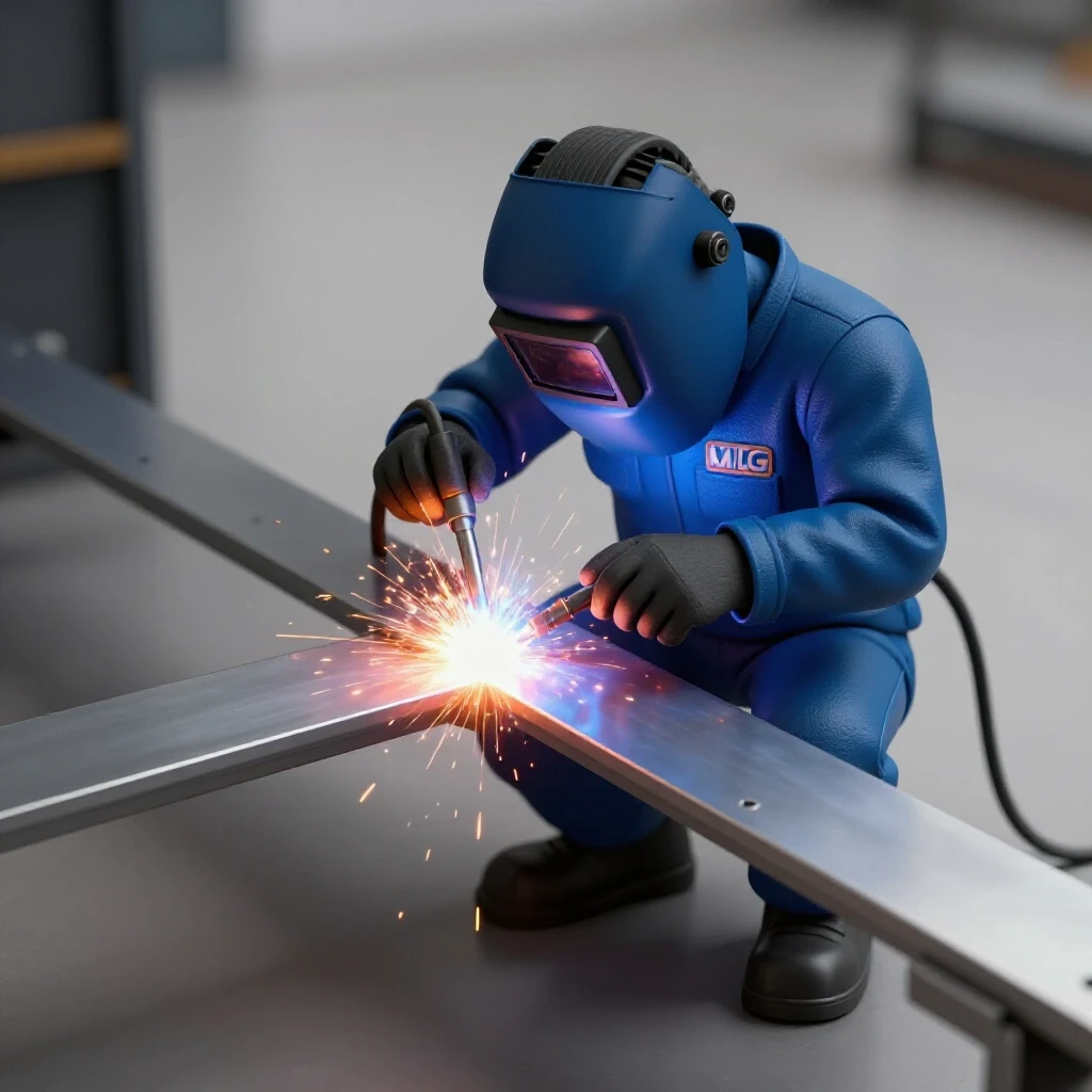
Short-circuit transfer is a welding mode where the wire electrode touches the base metal, causing a momentary short circuit that melts the wire and drops a bead of metal into the joint. This process repeats dozens of times per second, making it the primary method for joining thin materials without excessive heat.
In my experience, understanding this electrical cycle is the first step toward preventing structural metal load capacity issues. When you set your machine for thin gauges, you are essentially trying to create a stable, rapid-fire sequence of these short circuits. If the voltage is too high, the wire melts before it touches the pool, creating a spray that will instantly blow a hole through 1.0 mm steel. Conversely, if the voltage is too low, the wire will “stub” against the metal, causing the gun to kick back and leaving a cold, brittle weld with high internal stress.
Calibrating Electrical Potential for 0.5 mm to 2 mm Gauges
Setting the electrical potential, or voltage, for thin materials requires a narrow range, typically between 14 and 19 volts, to ensure the arc remains stable without over-penetrating the base metal. This setting acts as the “pressure” of the electricity, determining the width and height of the weld bead.
When I work with 18-gauge (about 1.2 mm) or 22-gauge (about 0.7 mm) steel, I always start at the lower end of the manufacturer’s suggested range. The goal is to find the “sweet spot” where the metal flows smoothly but the heat affected zone weakness is kept to a minimum. A wider bead usually indicates your voltage is too high for the thickness, which can lead to warping or a loss of structural integrity in the surrounding material.
| Material Thickness | Suggested Voltage Range | Wire Feed Speed (IPM) | Wire Diameter |
|---|---|---|---|
| 0.5 mm to 0.8 mm | 14 V – 15 V | 120 – 150 | 0.023 in |
| 1.0 mm to 1.2 mm | 15 V – 17 V | 160 – 210 | 0.023 in / 0.030 in |
| 1.5 mm to 2.0 mm | 17 V – 19 V | 220 – 280 | 0.030 in |
Why Wire Feed Speed and Voltage Must Be Synchronized
Wire feed speed (WFS) is the primary controller of amperage in a MIG system, and it must be perfectly balanced with the voltage to maintain a consistent arc length and prevent welding defect troubleshooting from becoming a full-time job. If the WFS is too high for the voltage, the wire will hit the plate too hard; if it is too low, the arc will burn back into the copper tip.
I often tell my team that the sound of the weld is your best diagnostic tool. A crisp, consistent “sizzle” like bacon frying usually indicates that your voltage and wire speed are in harmony. On thin sheet, this balance is even more critical because the margin for error is measured in fractions of a volt. Even a 0.5-volt adjustment can be the difference between a clean joint and a distorted mess that ruins the project’s structural design.
Managing Heat Input to Prevent Material Distortion
Heat input is the total amount of energy transferred to the workpiece per unit length of the weld, and on thin sheets, excessive heat leads to rapid expansion and permanent warping. Because thin metal has less mass to sink the heat away, the heat affected zone (HAZ) can quickly become a point of failure.
In my years of failure analysis, I have seen many fabricators try to “fix” a cold weld by simply turning up the voltage. This is a mistake. On thin gauges, you should instead focus on your travel speed and gun angle. If you move too slowly, the heat builds up in one spot, leading to burn-through. Keeping the voltage low and your travel speed high and consistent is the most reliable way to maintain the structural metal load capacity of the finished part.
- Keep the arc on the leading edge of the puddle.
- Use a “push” technique for better visibility and flatter beads.
- Limit the length of individual weld passes to 25 mm at a time.
- Allow the material to cool to the touch between passes.
Shielding Gas Flow Rates for Thin Metal Integrity
Shielding gas protects the molten weld pool from oxygen and nitrogen in the air, which can cause porosity and weaken the joint’s internal structure. For thin sheet work, a gas flow rate of 15 to 20 cubic feet per hour (CFH) is generally sufficient to provide coverage without causing turbulence.
I have investigated several garage fabrication safety incidents where poor gas coverage led to “Swiss cheese” welds that failed under minimal stress. If your flow rate is too high, it can actually pull air into the weld pool through a venturi effect. For thin materials, using a mix of 75% Argon and 25% CO2 provides a stable arc and a cooler weld puddle compared to 100% CO2, which is essential for preventing burn-through on 1.0 mm steel.
Selecting the Correct Wire Diameter for Low Voltage Work
The diameter of your welding wire significantly impacts the amount of heat required to melt it, with thinner wires like 0.023 inch (0.6 mm) being the industry standard for thin sheet applications. Using a wire that is too thick for the voltage setting will result in a cold, “roping” bead that sits on top of the metal rather than fusing with it.
When I am setting up a project involving 0.8 mm sheet, I always swap out 0.030 inch wire for 0.023 inch. The smaller wire requires less current to melt, which allows me to keep the voltage in the 14 V to 15 V range. This reduces the total energy entering the part and significantly lowers the risk of distortion. It is a simple mechanical change that dramatically improves the structural reliability of the fabrication.
Diagnostic Tests for Identifying Internal Weld Defects
Before committing to a final structural joint, I always perform a series of diagnostic tests on scrap material of the exact same thickness to verify that my voltage and wire speed are correct. These tests allow you to see how the metal reacts to the heat before you risk a failure on the actual project.
- The “T-Joint” Break Test: Weld a small T-joint on one side, then use a hammer to bend the vertical piece over the weld. If the weld snaps or pulls out of the base metal, your voltage was likely too low, causing poor fusion.
- The Penetration Check: Look at the back of a butt weld. You should see a slight, consistent heat tint or a very small “bead” of metal. If the back is clean, you have zero penetration; if there is a gaping hole, your voltage or heat input is too high.
- The Visual Porosity Audit: Inspect the surface for tiny pinholes. These are signs of gas flow issues or contaminated metal, which will drastically reduce the structural metal load capacity.
Troubleshooting Common Failures in Thin Gauge Welding
Even with the correct settings, issues can arise due to technique or environmental factors. Learning to identify these problems early is a hallmark of a professional fabricator and is essential for maintaining a safe workshop.
| Defect | Likely Cause | Recommended Correction |
|---|---|---|
| Burn-Through | Voltage too high or travel speed too slow | Lower voltage by 0.5 V or increase travel speed. |
| Excessive Spatter | Voltage too low for the wire feed speed | Increase voltage or decrease wire feed speed. |
| Lack of Fusion | Voltage too low or dirty base metal | Increase voltage and clean metal with a wire brush. |
| Warping/Distortion | Excessive heat input in a single area | Use “stitch” welds and allow for cooling periods. |
| Porosity | Low gas flow or wind interference | Increase gas flow to 20 CFH or block drafts. |
Structural Joint Verification Checklist
To ensure that your thin sheet projects are structurally sound and safe for their intended use, I recommend following a verification checklist for every critical joint. This systematic approach reduces the risk of human error and ensures consistency across the build.
- Material Prep: Is the mill scale, rust, and oil removed 25 mm back from the joint?
- Fit-Up: Is the gap between the pieces less than half the thickness of the material?
- Voltage Check: Is the machine set within the 14 V to 19 V range for the specific gauge?
- Gas Verification: Is the flow rate set between 15 and 20 CFH?
- Test Weld: Have you confirmed the settings on a scrap piece of the same material?
- Post-Weld Inspection: Are there any visible cracks, pinholes, or signs of undercut?
Conclusion and Next Steps for Safe Fabrication
Mastering the settings for thin sheet metal is a journey of precision and observation. By focusing on the narrow voltage window of 14 V to 19 V and balancing it with the correct wire feed speed, you can create structures that are both lightweight and incredibly strong. I have learned through years of inspection that the most dangerous failures are the ones you cannot see, such as internal lack of fusion caused by incorrect electrical settings.
As a next step, I encourage you to spend an hour in your shop strictly focused on “dialing in” your machine on scrap 1.2 mm steel. Experiment with moving the voltage up and down in 0.2-volt increments while keeping your wire speed constant. Take notes on the sound of the arc and the shape of the bead. This data-driven approach will build the muscle memory and technical intuition needed to tackle complex structural designs with confidence.
FAQ: Frequently Asked Questions About Thin Sheet Voltage Settings
What is the ideal voltage for 1.0 mm sheet metal?
For 1.0 mm steel, a starting point of 15.5 V to 16.5 V is usually effective. You want enough voltage to wet out the edges of the puddle but not so much that the arc becomes unstable or blows through the material. Always pair this with a 0.023 inch wire for the best control.
How do I know if my voltage is set too high?
The most obvious sign is burn-through, where the arc melts a hole completely through the sheet. Other signs include a very wide, flat bead, excessive heat tint far away from the weld, and a loud, “hissing” sound rather than a crisp crackle.
Can I weld 0.8 mm steel with 0.035 inch wire?
It is not recommended. 0.035 inch wire requires significantly more voltage and current to melt, which will almost certainly cause burn-through on 0.8 mm material. For anything under 1.5 mm, a 0.023 inch wire is the safest choice for maintaining structural integrity.
Why is my welder “stubbing” and pushing the gun back?
This is a classic sign that your voltage is too low for your wire feed speed. The wire is hitting the base metal before the electricity has a chance to melt it. To fix this, either increase your voltage by 0.5 V or slightly decrease your wire feed speed.
How does shielding gas affect my voltage needs?
Using a 75/25 Argon/CO2 mix generally allows for a smoother arc at lower voltages compared to 100% CO2. If you switch to pure CO2, you may find you need to increase your voltage slightly to maintain the same arc stability, but this also increases the heat input.
What is the “heat affected zone” and why does it matter?
The heat affected zone (HAZ) is the area of the base metal that was not melted but had its microstructure changed by the heat of the weld. In thin sheets, a large HAZ can make the metal brittle or prone to cracking. Keeping your voltage low and travel speed high helps minimize the size of the HAZ.
How can I prevent warping on long thin sheet joints?
Instead of one continuous bead, use the “stitch welding” technique. Place a 15 mm weld, then move to a completely different part of the joint and place another. This spreads the heat across the entire structure, preventing one area from expanding too much and causing a permanent warp.
Does the angle of the welding gun affect penetration?
Yes, a steep “push” angle (about 10 to 15 degrees) will result in shallower penetration and a flatter bead, which is ideal for thin sheet. A “pull” or “drag” angle increases penetration and can lead to burn-through on materials thinner than 2 mm.
(This article was written by one of our staff writers, James Harlan. Visit our Meet the Team page to learn more about the author and their expertise.)