How to Weld a Rustproof Ice Chest Cooler Stand Frame (Plan)
I remember the first time I built a custom chassis for a small utility trailer. I had spent hours measuring, marking, and cutting. Everything looked perfect on the layout table. But as soon as I finished the final weld on the main rails, I watched in horror as the back end lifted two inches off the table. The heat had pulled the metal into a permanent “smile.” That day, I learned that welding isn’t just about sticking two pieces of metal together; it is a constant battle against physics and thermal expansion.
In my 13 years as a prototype technician, I have seen many DIY builders face this same frustration. You want to build a durable, corrosion-resistant stand for an outdoor ice chest, but the metal seems to have a mind of its own. Whether you are using stainless steel or galvanized tubing, the challenge remains the same: how do you keep a rectangular frame square and flat when the very process of joining it wants to twist it into a pretzel? This guide focuses on the mechanics of building a stable, elevated platform that stays true to your original design.
Designing the Corrosion-Resistant Support Structure
Designing a frame involves more than just picking dimensions; it requires understanding how the load will be distributed and how the chosen material will behave under heat.
For a standard 48 to 72-quart cooler, a frame built from 1-inch square tubing with a 1/8-inch wall thickness is a solid choice. This provides enough strength to hold a full chest of ice and beverages without being excessively heavy. When working with materials like 304 stainless steel, you must account for its high rate of thermal expansion, which is significantly higher than carbon steel.
Establishing Dimensional Tolerances
Dimensional tolerances are the allowable limits of variation in a physical dimension. In custom fabrication, aiming for a tolerance of +/- 1/16th of an inch is a standard benchmark for high-quality work.
When you plan your layout, always measure the cooler you intend to use. A common mistake is building the frame to the exact dimensions of the cooler base. I always add a 1/4-inch “fudge factor” to the internal width and length. This ensures the chest drops in easily even if there is slight inward weld shrinkage or if the plastic of the cooler expands in the sun.
Calculating Material Kerf and Precision Cutting
Kerf is the width of the material removed by a cutting tool, such as a saw blade or a plasma torch. If you do not account for kerf, your finished frame will be shorter than your plan intended.
If you are using a dry-cut saw with a 1/8-inch thick blade, every cut removes 1/8 inch of metal. If you need four pieces at 24 inches and you just mark 24, 48, 72, and 96 on a single stick of tubing, your last piece will be nearly half an inch short. I always mark my “keep” side and cut on the waste side of the line to maintain accuracy.
| Cutter Type | Typical Kerf Width | Accuracy Level |
|---|---|---|
| Abrasive Chop Saw | 1/8″ – 5/32″ | Low (Heat/Burrs) |
| Cold Saw (Dry Cut) | 3/32″ – 1/8″ | High (Clean/Square) |
| Horizontal Bandsaw | 1/16″ – 3/32″ | Very High (Straight) |
| Angle Grinder (Zip Disc) | 1/16″ – 1/8″ | Moderate (User Dependent) |
Building Workshop Jigs for Frame Alignment
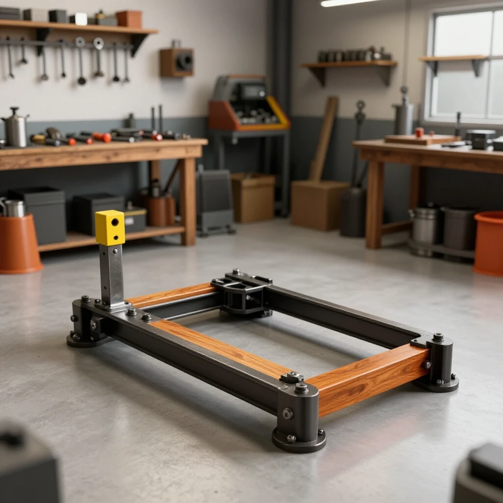
A jig is a custom-made tool used to hold parts in the correct position while they are being joined. Jigs are the only way to ensure repeatability and prevent the metal from moving during the tack-welding phase.
I never weld a frame directly on a wooden workbench. Wood is rarely flat and poses a fire hazard. Instead, I use a dedicated steel fabrication table or a set of heavy-duty sawhorses with a thick steel plate on top. For this project, a simple corner jig made from scrap angle iron can save you hours of frustration.
Using 3D Layout Templates and Clamps
Modern layout tools, such as 3D-printed corner guides or cast-iron welding squares, help hold the tubing at a perfect 90-degree angle. These tools act as an extra set of hands.
When setting up your frame, place a clamp every 6 to 8 inches if possible. This physical restraint resists the initial “pull” of the cooling weld puddle. I use F-style clamps or locking C-clamps. Interestingly, the more points of contact you have with your jig, the less likely the frame is to “diamond” (turn into a parallelogram) during the first few tacks.
Squaring the Base Frame
Squaring is the process of ensuring all corners are exactly 90 degrees by comparing diagonal measurements. If the diagonals are equal, the frame is square.
- Lay out your four perimeter pieces on the jig.
- Measure from the top-left corner to the bottom-right corner.
- Measure from the top-right corner to the bottom-left corner.
- If the measurements differ by more than 1/16th of an inch, tap the corners with a dead-blow hammer until they match.
- Secure all four corners with clamps before striking your first arc.
Strategic Tacking and Heat Management
A tack weld is a small, temporary weld used to hold components in place until the final beads are laid. Tacking is the most critical step in preventing project distortion.
Many builders make the mistake of tacking one corner and then immediately welding the whole joint. This is a recipe for disaster. As the weld cools, it shrinks. Because the other corners aren’t secured, that shrinkage will pull the entire frame out of alignment. I always use a four-point tacking strategy on every joint.
The Physics of Angular Weld Shrinkage
Angular shrinkage occurs when the top of a weld bead cools and contracts faster than the bottom, causing the metal pieces to “fold” toward the weld. This is why a flat frame often ends up looking like a shallow bowl.
To combat this, I place small, 1/8-inch tacks on the outside corners first. Then, I move to the opposite corner of the entire frame. This distributes the heat evenly across the structure. By the time I finish tacking all four corners, the first one has cooled enough to act as a rigid anchor.
Tack Spacing and Sizing
For 1-inch tubing, a tack should be no larger than a pea. If the tack is too large, it adds unnecessary heat; if it is too small, it might “pop” or crack when the frame starts to move under the stress of the main weld.
- Tack Count: 4 per mitered joint (one on each face of the square tube).
- Tack Size: 1/8″ to 3/16″ in diameter.
- Sequence: Diagonal pattern (Top Left, Bottom Right, Top Right, Bottom Left).
Mastering the Weld Sequence to Control Distortion
Weld sequencing is the specific order in which you lay your beads to balance the internal stresses of the metal. Think of it like tightening lug nuts on a car wheel.
If you weld all the joints on the top side of the frame first, the frame will bow upward. To keep it flat, you must alternate your passes. This is especially important with stainless steel, which holds heat longer than mild steel and is more prone to warping.
The “Back-Step” and Alternating Method
The back-step method involves welding in the opposite direction of the overall progression. However, for a simple rectangular stand, the alternating method is usually more effective.
I start by welding the outside vertical seams on two opposite corners. Then, I flip the frame and weld the same seams on the other side. By jumping around the project, I prevent any single area from getting too hot. If the metal becomes too hot to touch (even with gloves), I stop and let it air cool. Never quench a structural weld with water, as this can make the metal brittle and cause it to crack.
Managing Heat Sinks
A heat sink is a mass of metal placed near the weld zone to absorb and dissipate heat. This helps prevent the thin-walled tubing from melting through (burn-through) and reduces warping.
I often use thick copper blocks or even heavy scraps of aluminum as heat sinks. I clamp them right next to the joint I am welding. Because copper and aluminum conduct heat much faster than steel or stainless, they “suck” the excess thermal energy away from the weld, keeping the surrounding tubing cooler and straighter.
| Material | Thermal Conductivity (W/m·K) | Warping Risk |
|---|---|---|
| Mild Steel | 45 – 55 | Moderate |
| 304 Stainless Steel | 16 | High (Heat stays local) |
| Aluminum (for sinks) | 205 | Very High |
| Copper (for sinks) | 385 | Low (Excellent heat sink) |
Structural Integrity and Cross-Bracing
A stand for a heavy ice chest needs to resist lateral forces, also known as “rack.” If someone bumps into the stand, you don’t want the legs to fold.
Cross-bracing involves adding diagonal or horizontal members between the legs to create triangles. Triangles are the strongest shape in engineering because they do not deform under pressure. For a rustproof stand, I prefer a H-brace design. This involves a horizontal bar connecting the two front legs and another connecting the two back legs, with a center stringer joining the two.
Leg Leveling and Ground Contact
No garage floor or patio is perfectly flat. If you weld your stand with fixed legs, it will almost certainly wobble.
I solve this by welding threaded inserts (weld nuts) into the bottom of the square tubing legs. I then use stainless steel leveling feet. This allows you to adjust each leg individually, ensuring the cooler stays level even on uneven ground. When welding these inserts, be careful not to get spatter in the threads. I usually run a sacrificial bolt into the nut during welding to protect the internal threads.
Verifying Final Squareness
Once all the welding is complete and the frame has cooled to room temperature, it is time for the final check. Metal continues to move as it cools, so a frame that was square while hot might not be square an hour later.
- Re-measure the diagonals.
- Check the “flatness” by placing the frame on a known flat surface (like your welding table).
- If one corner is lifted, you can sometimes “cold-straighten” it using a large vise or by strategically applying a small amount of heat to the opposite side of the warp to “pull” it back. However, if you followed a strict weld sequence, this should be minimal.
Actionable Framework for the Build
To keep your project on track and avoid the common pitfalls of inaccurate cuts or heat distortion, follow this checklist. I use a similar log for every chassis I build in my shop.
- Material Prep: Clean all joints with a stainless steel wire brush. If using galvanized, grind off the zinc coating at least 1 inch back from the weld zone to avoid toxic fumes and porous welds.
- Cut List Verification: Double-check your measurements against the cooler. Remember the 1/4-inch clearance.
- Jig Setup: Clamp the perimeter pieces to the table. Ensure the “crown” (the natural slight curve in the tubing) is facing the same way for all pieces.
- Tack Sequence: Apply four small tacks per joint in a cross-pattern.
- Diagonal Check: Confirm the frame is square within 1/16th of an inch before final welding.
- Weld Sequencing: Move from corner to corner, alternating sides and faces to balance heat.
- Cooling: Allow the frame to cool naturally. Do not move it until it is cool to the touch.
- Leveling: Install threaded feet and adjust for stability.
Lessons from the Shop: Avoiding Rookie Mistakes
One of the biggest mistakes I see is “over-welding.” Builders often think that a bigger bead is a stronger bead. In reality, an oversized weld just adds more heat, which leads to more warping. For 1/8-inch wall tubing, a weld bead doesn’t need to be any thicker than the metal itself.
Another trap is ignoring the “fit-up.” If there are large gaps between your mitered corners, the weld puddle has to bridge that gap. This requires more heat and more filler metal, which significantly increases the “pull” on the joint. Spend the extra time with a flap disc or a file to make sure your joints are tight with no visible light shining through. A tight fit-up is the best defense against a warped frame.
Finally, always remember that stainless steel “pulls” much harder than mild steel. If you are used to welding carbon steel, you will need to be twice as diligent with your clamping and sequencing when working on a rustproof project.
Frequently Asked Questions
Why does my frame turn into a “diamond” shape after I weld the first two corners? This happens because the weld on the outside of the corner shrinks as it cools, pulling the joint open. Because the other corners aren’t tacked or clamped, the entire frame shifts to accommodate that movement. Always tack all four corners of the frame before doing any full-length welding.
Can I weld galvanized steel for this stand? Yes, but you must take safety precautions. Welding galvanized steel releases zinc oxide fumes, which can cause “metal fume fever.” Always grind off the galvanized coating in the weld area and work in a well-ventilated space or use a respirator with P100 filters.
How do I prevent the “bow” in the long spans of the tubing? This is usually caused by welding only on one side of the tube. To keep a long span straight, balance your welds. If you weld the top, you must weld the bottom. The opposing forces will cancel each other out, keeping the tube linear.
What is the best way to ensure the legs are perfectly vertical? Use a machinist’s square or a magnetic welding square to hold the leg at 90 degrees to the base frame. Tack it on two adjacent sides, re-check for square, and then finish the other two tacks. Never trust your eyes; always use a square.
Is TIG or MIG better for a corrosion-resistant stand? TIG (Tungsten Inert Gas) welding offers more control over heat and produces cleaner, more precise welds, which is ideal for stainless steel. MIG (Metal Inert Gas) is faster and easier for beginners. Both are acceptable as long as you use the correct filler wire (e.g., 308L for stainless steel).
How much clearance should I leave for the cooler? I recommend at least 1/8 inch on all sides (1/4 inch total added to length and width). This accounts for the manufacturing tolerances of the plastic cooler and any minor inward pull of the metal during welding.
What should I do if the frame is slightly wobbly after welding? This is where leveling feet come in. Even a perfectly welded frame can wobble if the floor isn’t flat. Using threaded inserts and adjustable feet is the professional way to solve this without trying to bend the metal.
Do I need to weld all the way around every joint? For a structure holding a heavy load like a 72-quart cooler, yes. Full-perimeter welds ensure maximum strength and prevent water from getting inside the tubing, which could cause internal corrosion over time.
How do I calculate the weight capacity of the stand? A 72-quart cooler full of ice and water can weigh over 150 pounds. 1-inch square tubing with a 1/8-inch wall is rated for much higher loads than this, provided your welds have good penetration and you have included basic cross-bracing.
What is the most common cause of “burn-through”? Burn-through happens when the metal gets too hot and the weld puddle falls through. This is usually caused by moving the torch too slowly or having the amperage set too high for the wall thickness of the tubing. Practicing on scrap pieces of the same thickness is essential.
Building a custom support for your gear is a rewarding project that tests your layout and heat management skills. By focusing on the physics of the weld and maintaining a disciplined sequence, you can create a structure that is both functional and professionally executed. The key is patience: measure twice, clamp tightly, and let the metal cool.
(This article was written by one of our staff writers, Robert Kline. Visit our Meet the Team page to learn more about the author and their expertise.)