How to Weld Thin Sheet Metal Without Burn-Through (Tutorial)
After 17 years of tearing down machinery and running side-by-side tests in my shop, I have learned that marketing stickers rarely tell the truth about a tool’s performance. When you are trying to join metal that is thinner than a penny, the difference between a high-quality inverter and a budget-box transformer becomes painfully obvious. I have seen countless fabricators struggle with blown-out holes and warped workpieces, not because they lacked skill, but because their equipment lacked the arc stability required for delicate work.
Choosing workshop machinery is a process of looking past the paint job to see the internal components. In my time as a maintenance specialist, I have repaired electrical driver boards and replaced cheap plastic drive rollers that failed under the slightest pressure. To successfully fuse materials between 0.5 mm and 1.5 mm, you need a machine that offers granular control over heat input. This guide focuses on the mechanical and electrical realities of managing low-current arcs for thin-gauge projects.
Evaluating Power Source Architecture for Low-Current Stability
The power source architecture determines how consistently a machine can maintain a tiny arc without flickering or surging. For thin-gauge work, the ability to hold a steady output at 20 to 30 amps is the difference between a clean bead and a ruined part.
In my shop, I have compared older transformer-based units with modern inverter technology. Transformers are rugged, but they often struggle to stay stable at the very bottom of their amperage range. Inverters use high-speed silicon switches to “chop” the incoming power, providing a much smoother DC output. When you are working with 1.0 mm steel, that smoothness prevents the “stuttering” that often leads to localized overheating and subsequent holes in the workpiece.
Understanding Inverter vs. Transformer Efficiency
Electrical efficiency in a welder refers to how much of the wall power is converted into a usable arc versus how much is lost as heat inside the machine. High-efficiency inverters allow for much finer adjustments in the low-range settings needed for thin materials.
| Feature | Transformer Machines | Inverter Machines |
|---|---|---|
| Low-Amp Stability | Often “choppy” below 50A | Extremely stable down to 5A-10A |
| Weight/Portability | Heavy (75+ lbs) due to copper coils | Light (15-30 lbs) using PCBs |
| Arc Control | Basic voltage taps | Infinite variable control/Pulse |
| Internal Cooling | Large fans, lower duty cycle | High-efficiency heat sinks |
If you are choosing between these technologies, the inverter is almost always the better investment for thin-gauge fabrication. The ability to dial in 27 amps instead of choosing between a “Low” or “Medium” switch gives you the precision necessary to avoid over-penetration.
Why Wire Drive Systems Impact Thin-Gauge Success
The wire drive system is the mechanical heart of a MIG welder, consisting of the motor, drive rolls, and tensioning assembly. For thin-gauge work using 0.6 mm (0.023 in) wire, any slip or stutter in this system will cause the arc to fluctuate and burn through the metal.
I always tell people to ignore the brand name and look at the drive roll housing. I have seen $800 machines with plastic drive assemblies that flex under tension. A professional-grade machine should have a cast aluminum or heavy-duty steel drive system. This rigidity ensures that the wire feeds at a constant velocity, which is critical when your travel speed must be fast and consistent to prevent heat buildup.
Drive Roll Quality and Spindle Runout
Spindle runout in a wire drive refers to any wobbling or off-center rotation of the drive rolls. Even a few thousandths of an inch of runout can cause the wire to feed in pulses rather than a steady stream.
- Cast Aluminum Housings: These provide better thermal management for the drive motor and resist flexing better than plastic.
- Dual-Driven Rolls: Systems where both the top and bottom rolls are geared together offer more consistent feeding of small-diameter wires.
- Tension Indicators: Look for a calibrated scale on the tensioner so you can repeat your settings once you find the “sweet spot” for 0.6 mm wire.
Joint Preparation and the Reality of Fit-Up
Fit-up is the physical alignment and gap between two pieces of metal before they are joined. When working with 0.8 mm sheet, a gap as small as 0.5 mm can be a disaster, as the arc will naturally want to melt the thin edges rather than bridge the space.
In my experience, many fabricators blame their machine when the real culprit is a sloppy fit-up. I use a “zero-gap” policy for thin materials. This means the edges must be perfectly square and touching along the entire length of the joint. If you can see light through the joint, you are likely to experience melt-through.
Precision Alignment Tools
To achieve the necessary alignment, you need tools that can hold thin sheet without bowing it. I prefer using copper-backed magnets or specialized sheet metal clamps.
- C-Clamps with Swivel Pads: These prevent the metal from shifting as you tighten them.
- Copper Backing Bars: Placing a piece of copper behind the joint acts as a “heat sink” and a physical barrier that prevents the molten puddle from falling through.
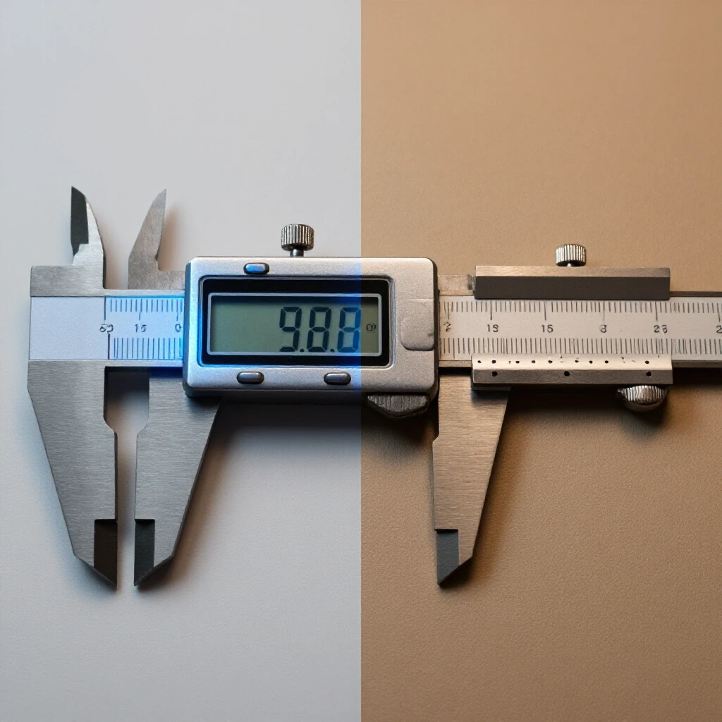
- Digital Calipers: Use these to verify that your material thickness is consistent across the joint.
Thermal Management Through Stitch Welding
Stitch welding is a technique where you place a series of small, individual welds (tacks) rather than running a continuous bead. This allows the heat to dissipate between increments, keeping the overall temperature of the sheet metal below its melting point.
When I am testing a new machine’s low-end performance, I look at how quickly the arc initiates. For stitch welding, you need a crisp, “hot” start that doesn’t stick. If the machine’s control board is poorly designed, there will be a delay, causing you to linger too long in one spot and overheat the metal.
The “Skip” Technique for Distortion Control
To prevent the metal from warping or blowing out, you should never weld in a straight line from start to finish. Instead, place a tack at the beginning, one at the end, and one in the middle. Then, “skip” around, placing tacks in the cool areas between previous welds.
- Tack Size: Keep tacks no larger than 2-3 times the thickness of the metal.
- Cooling Time: If the metal is too hot to touch with a gloved hand, wait before the next stitch.
- Travel Speed: When you do run short beads, move 20-30% faster than you would on thicker plate.
Consumable Selection: Wire Diameter and Tungsten Geometry
Consumables are the parts of the tool that wear out, such as the welding wire or the tungsten electrode. Using the wrong size consumable is like trying to do fine engraving with a sledgehammer.
For MIG welding on 1.0 mm steel, I always switch to 0.6 mm (0.023 in) wire. Most machines come standard with 0.8 mm or 0.9 mm wire, but these require more current to melt, which increases the risk of burning through the workpiece. By using a thinner wire, you can maintain a stable arc at a lower amperage.
Tungsten Grinding for TIG Precision
If you are using TIG, the shape of your tungsten electrode is a critical mechanical spec. A sharp, longitudinal grind (lines running toward the point) focuses the arc into a narrow cone.
- Truncated Tip: I prefer a slight flat spot (land) on the end of the sharp point. This prevents the very tip from breaking off and falling into the puddle.
- Tungsten Diameter: Use a 1.6 mm (1/16 in) electrode for thin work. A 2.4 mm electrode will have a “lazy” arc at low currents.
- Gas Lens: Replace the standard collet body with a gas lens. It provides a more stable, laminar flow of shielding gas, which helps cool the weld area and stabilize the arc.
The Role of Inductance and Pulse Settings
Inductance is an electrical property that controls how fast the current rises when the wire touches the metal. In MIG welding, higher inductance creates a “softer” arc with less spatter, which is often preferred for thin-gauge work because it reduces the “punch” of the arc.
Pulse TIG is another high-end feature that is worth the investment for thin materials. It alternates the current between a high “peak” (to melt the metal) and a low “background” (to let it cool). This keeps the average heat input much lower than a standard constant-current arc.
Comparative Tool Matrix: Control Features
| Feature | Impact on Thin Metal | Recommended Setting |
|---|---|---|
| Inductance | Softens arc, reduces “dig” | Increase for thinner gauges |
| Pulse Frequency | Constricts arc, reduces heat | 50-100 Pulses Per Second (PPS) |
| Burnback Control | Prevents wire sticking in puddle | Set to minimum required |
| Pre-Flow Gas | Protects start of weld | 0.5 – 1.0 seconds |
Identifying Performance Realities in Shop Machinery
When you are researching tool purchases, you will see a lot of talk about “Max Amps.” For thin-gauge work, you should be looking at the “Minimum Amps.” A machine that goes up to 250 amps but can’t run smoothly below 40 amps is useless for 0.5 mm sheet.
I also look at the quality of the potentiometers (the knobs) on the front panel. Are they indexed and firm, or do they feel loose? On a high-quality machine, the electronics should allow for 1-amp increments. If the dial feels like a “suggestion” rather than a precision control, you will struggle to find the exact heat setting needed to avoid burn-through.
Checklist for Evaluating a New Welder
- Check the minimum amperage: Ensure it can go down to at least 10A for TIG or 25A for MIG.
- Inspect the drive rolls: Look for metal construction and geared rollers.
- Verify the warranty: Does it cover the inverter boards, which are the most expensive parts to replace?
- Test the arc start: It should be instantaneous without “popping” or sticking.
- Look for Pulse features: Especially if you plan on doing a lot of work under 1.0 mm.
Why Heavy Castings and Rigid Frames Matter
While the welding process itself is electrical, the setup is mechanical. If your welding table or your clamps are made of thin, flimsy steel, they will warp along with your workpiece. I always recommend a heavy, cast-iron or thick steel welding platen for thin-gauge work.
Heavy castings dampen the thermal expansion of the metal being welded. If you clamp a 1.0 mm sheet to a 20 mm thick steel table, the table acts as a massive heat sink. This “thermal mass” pulls heat away from the weld zone, significantly reducing the chance of the metal reaching its melting point too quickly and blowing out.
Measuring Alignment and Flatness
Before you strike an arc, use a straightedge to check the flatness of your work surface. If your table is bowed by even 1.0 mm, your thin sheet will follow that curve, creating internal stresses. When you add the heat of the weld, those stresses will release, causing the metal to “oil-can” or pop out of shape.
- Total Indicated Runout (TIR): While usually applied to lathes, think of this as the “runout” of your flat surface. Aim for a surface flat within 0.1 mm across the work area.
- Clamping Pressure: Use enough pressure to keep the metal in contact with the heat sink, but not so much that you deform the thin sheet.
Spare Parts and Long-Term Maintenance
A machine is only as good as the parts you can get for it. In my 17 years of maintenance, I have seen many “budget” machines become boat anchors because a $5 plastic fan or a specific control chip was no longer available.
When choosing workshop machinery, check the availability of consumables like contact tips, gas diffusers, and liners. If these are proprietary and only sold by one vendor, you are at their mercy. I prefer machines that use “Euro-style” torches or standard Tweco/Binzel consumables. This ensures that even if the manufacturer goes out of business, you can keep your machine running.
Planning Your Consumable Supply
- Contact Tips: Buy them in bulk. A worn tip causes micro-arcing inside the torch, which leads to erratic wire feeding.
- Liners: Replace your torch liner every 5-10 rolls of wire. A dirty liner is the leading cause of “stuttering” in thin-wire MIG welding.
- Drive Rolls: Keep a spare set of V-groove (for hard wire) or U-groove (for soft wire) rolls on hand.
Conclusion: Making a Confident Investment
Successfully joining thin-gauge metal is a test of both the fabricator’s patience and the machine’s precision. By looking past the marketing hype and focusing on the mechanical drive systems, electrical stability, and thermal management features, you can select a tool that makes the job easier rather than more frustrating.
Remember that the most expensive machine isn’t always the best, but the cheapest machine is almost always a compromise. Look for an inverter with a stable low-end, a rigid metal wire drive, and the ability to use standard consumables. With the right equipment and a focus on perfect fit-up and heat-sink techniques, you can produce professional-grade results on even the thinnest materials.
FAQ
What is the best wire size for 0.8 mm sheet metal?
I recommend using 0.6 mm (0.023 in) ER70S-6 wire. It requires less amperage to melt than 0.8 mm wire, which gives you a wider margin of error before the metal burns through. It also allows for a more stable arc at the low voltage settings required for thin gauges.
Can I use flux-core wire on thin sheet metal?
Flux-core is generally not recommended for material thinner than 1.5 mm. It runs hotter than solid wire with shielding gas and produces more spatter. The slag inclusion risk is also higher on thin joints where you cannot easily grind out defects.
Why does my welder keep “popping” at low settings?
This is usually caused by a poor wire drive system or an unstable power source. If the wire is slipping or the motor is hunting for speed, the arc will break and restart, causing a “pop.” Check your drive roll tension and ensure your contact tip is the correct size for the wire.
How do I stop thin metal from warping?
Warping is caused by uneven heating and cooling. Use the skip-welding technique, keep your tacks small, and use a copper backing bar to sink the heat. Clamping the workpiece to a thick steel or cast-iron table also helps maintain flatness.
Is TIG or MIG better for very thin metal?
TIG offers the ultimate control because you can manage the amperage with a foot pedal and add filler metal only when needed. However, MIG is much faster and easier to learn. For anything under 0.8 mm, TIG is generally the preferred process for professional results.
What gas should I use for MIG welding thin steel?
A 75% Argon / 25% CO2 mix is the industry standard. The Argon provides arc stability and reduces spatter, while the CO2 provides the necessary penetration. For extremely thin work, some use a 90/10 mix to further reduce heat, but 75/25 is the most versatile.
Do I need a pulse welder for sheet metal?
While not strictly necessary, a pulse-capable machine makes thin-gauge work significantly easier. It allows you to achieve penetration with the “peak” current while the “background” current prevents the puddle from getting too hot and falling through.
How important is the “duty cycle” for thin metal?
For thin metal, duty cycle is rarely an issue. Since you are running at very low amperages (e.g., 30A), even a machine with a 20% duty cycle at its max power will likely run at 100% duty cycle at these low levels. Focus more on arc stability than duty cycle.
What is “burnback control” and do I need it?
Burnback control is a timer that keeps the welding power on for a fraction of a second after the wire stops feeding. This prevents the wire from sticking in the cooling weld puddle. It is very helpful for the “stitch welding” technique used on thin metal.
Can I weld thin aluminum with a standard MIG?
It is very difficult. Aluminum requires a spool gun or a “push-pull” drive system because the soft wire tangles easily. It also dissipates heat very quickly, making the line between “not melted” and “puddle on the floor” extremely thin. TIG is much better for thin aluminum.
(This article was written by one of our staff writers, Steven Brooks. Visit our Meet the Team page to learn more about the author and their expertise.)