How to Weld Heavy Duty Hitch Receiver Plates Safely (Guide)
I remember the first time I tried to mount a 5/8-inch steel plate to a square receiver tube for a custom utility trailer. I had spent three hours measuring, grinding, and cleaning the metal until it looked like a mirror. I clamped it down, felt confident, and ran a heavy bead of 7018 rod along the top edge. When I unclamped it twenty minutes later, my heart sank. The heat had pulled that heavy plate nearly an eighth of an inch out of square. The receiver tube was tilted, and no matter how hard I hit it with a sledgehammer, it wouldn’t budge.
That day taught me that fabrication isn’t just about melting metal together. It is a constant battle against physics. When we work on mounting structural plates for towing components, we are dealing with massive thermal forces. Steel expands when it gets hot and shrinks as it cools. If you don’t have a plan to manage that shrinkage, your project will warp, twist, and fail to align with your vehicle frame. My goal today is to walk you through the structural logic and sequence I use to keep these heavy-duty assemblies straight and safe.
Planning the Layout and Material Selection for Structural Hitch Mounts
Success in the shop starts on the workbench long before you ever strike an arc. When you are fabricating a mounting point that will see significant tongue weight and pulling force, material choice and cut accuracy are your primary foundations. I typically lean toward ASTM A36 mild steel for these projects because it provides a predictable balance of strength and weldability.
Designing your cut list requires you to account for the “kerf,” which is the width of the material removed by your cutting tool. If you are using a standard abrasive chop saw, you might lose 1/8 of an inch per cut. If you ignore this, a 12-inch plate suddenly becomes 11-7/8 inches, throwing off your entire alignment. I always mark my lines with a carbide scriber rather than a soapstone for high-precision layouts, as a soapstone line can be 1/16 of an inch thick on its own.
| Cutter Type | Typical Kerf Allowance | Best Use Case |
|---|---|---|
| Abrasive Chop Saw | 1/8″ (0.125″) | Rough sizing of thick plate |
| Portable Band Saw | 1/32″ (0.035″) | Precision square cuts |
| Oxy-Fuel Torch | 1/16″ to 3/16″ | Beveling heavy edges |
| Cold Saw | 3/32″ (0.090″) | Clean, burr-free structural cuts |
Interestingly, the way you prep the edges of your plate is just as important as the dimensions. For plates thicker than 3/8 of an inch, a square butt joint isn’t enough. You need to grind a 30 to 45-degree bevel on the mating edges to ensure the weld bead penetrates deep into the root of the joint. Without this “V-groove” preparation, you are only welding the surface, which can lead to structural failure under the rhythmic stress of towing.
Why Weld Shrinkage Warps Square Structures
When you lay down a bead of molten metal, it occupies more volume than it does when it is cold. As that bead solidifies and cools to room temperature, it acts like a powerful rubber band, pulling the two pieces of steel toward the center of the weld. This is known as angular distortion. In my years as a prototype technician, I’ve seen this force snap heavy-duty C-clamps and bow 1-inch thick base plates.
Understanding the “pull” of a weld is the difference between a project that fits and one that ends up in the scrap bin. If you weld only one side of a hitch plate, the cooling metal will pull the plate toward that bead. To counter this, we use a concept called “weld sequencing.” This involves jumping around the project to balance the heat and the resulting tension. If I weld two inches on the left, I immediately move to the right side to create an opposing force.
Building on this, you must consider the thickness of your material. A 1/2-inch plate has a much higher “heat sink” capacity than a 3/16-inch tube. This means the plate will suck heat away from the weld zone faster, potentially leading to a “cold start” where the weld doesn’t properly fuse to the plate. I often use a propane torch to pre-heat the heavy plate to about 200 degrees Fahrenheit. This reduces the thermal shock and allows the puddle to flow more smoothly into the thick steel.
Building Robust Workshop Jigs and Fixtures for Alignment
You cannot hold a heavy-duty hitch assembly square by hand, and standard spring clamps are useless against the forces of weld shrinkage. You need a dedicated fixture. A fixture is essentially a temporary frame that locks your workpieces into the correct orientation. For a hitch plate project, I often build a “T-jig” out of scrap 2×2 square tubing or heavy angle iron.
I bolt or clamp the receiver tube into this jig, ensuring it is perfectly perpendicular to the mounting plate. By securing the pieces to a larger, more rigid structure, you force the weld shrinkage to work against the jig rather than pulling the project out of alignment. As a result, the internal stresses are contained until the metal has cooled completely.
- Fixture Span Recommendations: For a standard 12-inch mounting plate, your fixture should extend at least 4 inches beyond the edges of the plate to provide adequate clamping leverage.
- Clamp Spacing: Place heavy-duty F-clamps or C-clamps every 3 to 4 inches along the joint to prevent the plate from “walking” or lifting during the tacking phase.
- Heat Sinks: If possible, clamp a thick block of aluminum or copper behind the weld zone. These materials dissipate heat rapidly, which can help minimize the overall thermal expansion of the steel plate.
One mistake I see often is unclamping the project too soon. I’ve made this error myself. You finish the weld, it looks great, and you want to see the final result. But if the steel is still over 300 degrees, it is still moving. I leave my projects in the fixtures until they are cool enough to touch with a gloved hand. This patience ensures that the metal has reached its final stable state while still under restraint.
Mastering the Structural Tacking Process
Tack welds are the “stitches” that hold your project together before the final “surgery.” For heavy plate fabrication, a tiny 1/8-inch tack is insufficient. It will likely snap the moment the main weld bead starts to pull. I prefer “bridge tacks” that are at least 3/4 of an inch long and have deep penetration.
The sequence of your tacks is just as critical as the sequence of your final beads. I start by placing one tack in the center of the joint, then I check for square. If it moved, I can still nudge it back with a hammer. Once it’s square, I place tacks at the extreme ends of the joint. This “center-out” approach helps distribute the initial tension evenly.
- Clean the area: Use a flap disc to remove all mill scale and rust within two inches of the tack site.
- Set the gap: Use a 3/32-inch welding rod or a specialized spacer to maintain a consistent root gap between the plate and the tube. This allows the weld to penetrate all the way through.
- Tack and check: After every two tacks, use a machinist’s square to verify the 90-degree alignment.
- Opposing tacks: If you tack the front, immediately tack the back in the same location to balance the pull.
In my workshop, I aim for a tack spacing of roughly 2 to 3 inches on heavy-duty plates. If the plates are particularly thick, I might even use a “heavy tack,” which is essentially a short, full-penetration weld bead. These tacks become part of the final weld, so they must be cleaned of all slag before you weld over them.
Executing the Final Weld Sequence for Heavy-Gauge Plate
Once the assembly is tacked and secured in the fixture, it’s time for the final passes. For structural hitch plates, I almost always use a “back-stepping” technique. Instead of starting at one end and welding all the way to the other, I break the joint into 3-inch segments. I start 3 inches from the end and weld toward the edge. Then, I move back another 3 inches and weld toward the start of the previous bead.
This method is incredibly effective at controlling heat. By welding toward a finished bead, you are “locking” the metal into place. It also prevents the heat from building up in one continuous wave, which is what usually causes a plate to bow. I also recommend alternating sides of the tube. Weld one segment on the left, then move to the right side and weld a segment there. This keeps the thermal forces balanced across the centerline of the receiver.
| Weld Sequencing and Distortion Control | ||
|---|---|---|
| Strategy | Description | Effectiveness |
| Back-stepping | Welding in short segments toward the previous bead | High—minimizes longitudinal shrinkage |
| Skip Welding | Jumping from one side of the project to the other | Medium—prevents localized overheating |
| Opposing Beads | Placing beads on opposite sides of a structural member | High—balances angular pull |
| Pre-setting | Angling the plate slightly away from the weld | Expert—uses shrinkage to pull the plate into square |
When welding 1/2-inch plate, you will likely need multiple passes. The first pass is the “root pass,” which should bridge the gap and fuse the bottom of the V-groove. After cleaning the slag, the second and third passes (the “filler” and “cap”) are added to build the weld up to the required thickness. Never try to fill a large gap in a single, slow pass; the excessive heat input will almost certainly cause massive warping.
Post-Weld Inspection and Correcting Minor Heat Distortion
Even with the best fixtures and sequencing, metal is stubborn. Once the project has cooled and you’ve removed it from the jig, you need to perform a final inspection. I use a long straightedge and a set of calipers to check for any bowing in the plate. My personal tolerance for a hitch mount is +/- 1/16 of an inch over a 12-inch span. Anything more than that can make it difficult to bolt the plate to the vehicle frame.
If you find that the plate has bowed slightly, you can sometimes correct it using “mechanical persuasion.” This might involve placing the plate in a hydraulic shop press and applying just enough pressure to move it back past its elastic limit. Another technique is “flame straightening,” where you use an oxy-acetylene torch to heat the side opposite the weld. As that spot cools, it shrinks and pulls the plate back in the other direction. However, this requires a delicate touch and a lot of experience to avoid making the problem worse.
- Dimensional Check: Measure the distance between mounting holes at the top and bottom of the plate to ensure they haven’t “pinched” together.
- Angular Check: Place the assembly on a known flat surface (like a cast-iron table) and check for any rocking or daylight under the plate.
- Weld Profile: Ensure the beads are slightly convex (humped) rather than concave (dipped). A concave weld is often thin in the center and prone to cracking under stress.
Safety Essentials and PPE for High-Heat Arc Welding
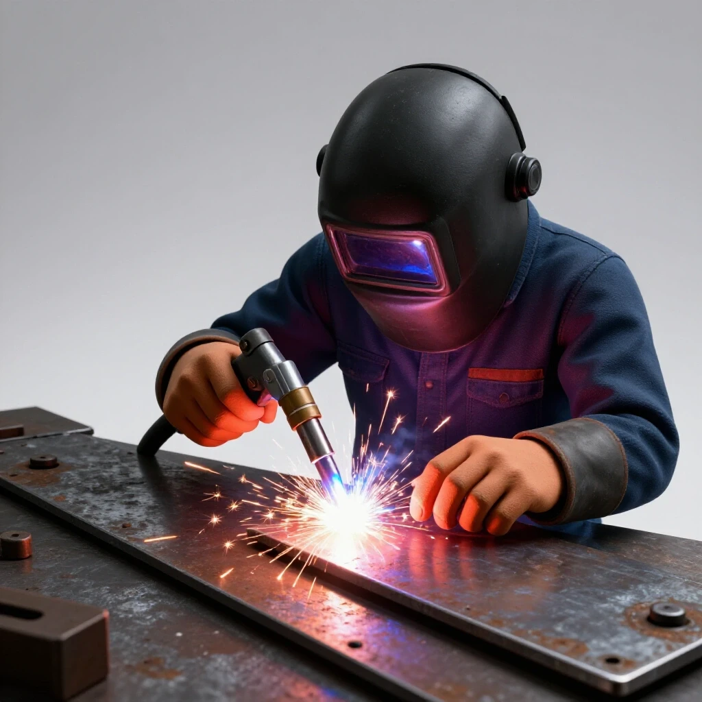
Working with heavy-duty plates means high amperage, which translates to a lot of light and heat. When I’m burning 1/8-inch 7018 rods at 125 amps, the UV radiation is intense. I always upgrade to a Shade 11 or 12 lens in my auto-darkening helmet to prevent eye fatigue. It’s also vital to wear a heavy leather apron and sleeves. Spatter from thick plate welding tends to be larger and holds heat longer than the “sparks” from thin sheet metal.
Respiratory protection is another area where I don’t compromise. Welding through mill scale or using certain types of rods can release harmful fumes. I use a low-profile respirator that fits comfortably under my welding hood. Building structural projects in a garage often means limited airflow, so having a dedicated exhaust fan or at least keeping the big door open is a must.
- Helmet: Auto-darkening with a fast reaction time (1/20,000 sec).
- Gloves: Heavy-duty MIG/Stick leathers with Kevlar stitching.
- Footwear: Steel-toed leather boots (spatter can melt through synthetic laces and mesh).
- Fire Safety: Keep a fire extinguisher within arm’s reach and clear all sawdust or rags from the area before you start.
Project Blueprint and Tracking Framework for Custom Hitch Fabrication
To consistently produce high-quality work, I recommend keeping a build log. I started doing this years ago, and it’s the best way to troubleshoot why a project went sideways. For every hitch plate I weld, I record the settings and the results. This data becomes your “cheat sheet” for the next time you have a similar project on the bench.
Actionable Alignment Checking Steps: 1. Level the Base: Ensure your welding table is level before you start. If the table is twisted, your project will be too. 2. Diagonal Measurements: For rectangular plates, always measure from corner to corner. If the measurements are equal, the plate is square. 3. Tack-Weld Log: Note where you placed your tacks and if the plate moved during the process. 4. Heat Tracking: If you have an infrared thermometer, check the temperature of the plate between passes. Try to keep the “interpass temperature” below 500 degrees Fahrenheit to prevent the grain structure of the steel from becoming brittle.
By following these steps, you move from “guessing and hoping” to a structured, engineering-based approach. Fabrication is a skill that rewards patience and preparation. When you take the time to build a jig, plan your sequence, and manage your heat, you end up with a project that isn’t just strong—it’s straight and professional.
Frequently Asked Questions
How thick should the mounting plate be for a heavy-duty hitch? For most custom utility applications, a plate thickness of 1/2 inch to 5/8 inch is standard. This provides enough mass to handle the weld heat and the structural rigidity to resist bending under tongue weight. Always match the plate thickness to the factory specs of the receiver tube you are using.
Can I use a standard MIG welder for this project? Yes, but you need a machine with enough amperage to get deep penetration into 1/2-inch steel. Most 110V household welders won’t cut it. You typically need a 220V machine capable of at least 200 amps. If you are using MIG, a gas mix of 75% Argon and 25% CO2 is standard for mild steel.
What is the best welding rod for structural plates? The E7018 “low-hydrogen” rod is the industry standard for structural welding. It produces a very strong, ductile weld that can withstand vibrations and impact. However, 7018 rods must be kept dry, as they absorb moisture from the air which can cause weld porosity.
How do I prevent the receiver tube from pulling to one side? The best way is to use “opposing welds.” If you weld a 2-inch bead on the left side, immediately move to the right side and weld a 2-inch bead there. This balances the shrinkage forces. Using a heavy fixture to lock the tube in place is also highly recommended.
Should I grind the welds flat for a better look? For structural hitch projects, I advise against grinding welds flush. The “throat” or thickness of the weld bead provides the strength. If you grind it flat, you are removing material and potentially weakening the joint. A light cleanup with a wire wheel is usually sufficient.
What is “root penetration” and why does it matter? Root penetration is how deep the weld goes into the base of the joint. If you only weld the surface, the joint can act like a hinge and crack under load. By grinding a bevel and leaving a small gap, you ensure the weld fuses the entire thickness of the metal.
How long should I wait for the project to cool before unclamping? Ideally, you should wait until the metal is cool enough to touch comfortably with a gloved hand. This usually takes 20 to 30 minutes for heavy plate. Unclamping while the metal is still “red hot” or even “blue hot” allows the remaining thermal stresses to warp the assembly.
Why did my tack welds snap when I started the main bead? This usually happens because the tacks were too small or the main weld bead created more shrinkage force than the tacks could handle. For 1/2-inch plate, your tacks should be substantial—at least 3/4 of an inch long—and you should have them spaced every few inches.
Can I use water to cool the weld faster? No. Quenching a structural weld with water can make the steel brittle and prone to cracking. It can also cause extreme warping as the metal shrinks too rapidly. Always allow structural projects to air-cool naturally at room temperature.
How do I know if my weld has enough penetration? On a beveled joint, you should be able to see the “root pass” bulging slightly through the back side of the joint. This is called “full penetration.” If you can’t see the back side, you have to rely on your welder settings and ensuring you are getting a good “crackle” sound and a consistent puddle width.
(This article was written by one of our staff writers, Robert Kline. Visit our Meet the Team page to learn more about the author and their expertise.)