How to Build Heavy-Duty Folding Steel Sawhorses (DIY Plan)
I remember the first set of chassis stands I built in my garage about a decade ago. I had spent hours measuring and cutting, feeling confident that my math was perfect. But as soon as I finished the final welding pass on the main crossbeam, I watched in frustration as the leg assembly pulled nearly a quarter-inch out of square. The culprit wasn’t my tape measure; it was the physics of heat. That experience taught me that in custom fabrication projects, the difference between a tool that lasts a lifetime and a wobbly pile of scrap lies in how you manage material behavior and weld sequencing.
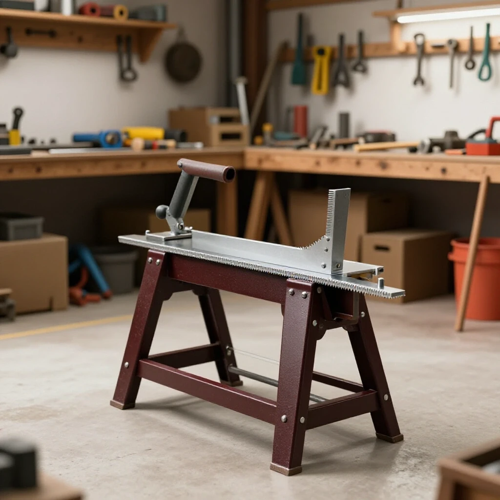
Building a set of collapsible steel trestles requires more than just a welder and some tubing. It demands a systematic approach to layout, a deep understanding of how metal moves when heated, and a commitment to tight tolerances. When you are constructing shop equipment meant to support hundreds of pounds of raw material, structural integrity and stability are non-negotiable. This guide breaks down the process of creating high-capacity, folding metal supports while addressing the common pitfalls of distortion and misalignment.
Planning Your Steel Support Project: Blueprints and Material Selection
Effective fabrication begins with a detailed plan that accounts for the physical properties of the steel and the intended load capacity of the finished unit. Choosing the right wall thickness and profile is the first step in ensuring your shop fixtures don’t buckle under pressure.
For heavy-duty applications, I typically lean toward 2″ x 3″ or 2″ x 4″ rectangular tubing with a 1/8″ (0.125″) wall thickness for the main spine. This provides a high moment of inertia, meaning it resists bending much better than square tubing of the same weight. For the legs, 1.5″ or 2″ square tubing is standard. If you anticipate loading more than 2,000 pounds per pair, stepping up to a 3/16″ (0.1875″) wall thickness is a smart move, though it increases the overall weight significantly.
| Material Profile | Wall Thickness | Estimated Load Capacity (Pair) | Weight per Foot |
|---|---|---|---|
| 2″ x 3″ Rectangular Tubing | 1/8″ (0.125″) | 1,500 lbs | 3.90 lbs |
| 2″ x 4″ Rectangular Tubing | 1/8″ (0.125″) | 2,200 lbs | 4.75 lbs |
| 2″ x 4″ Rectangular Tubing | 3/16″ (0.1875″) | 3,500 lbs | 6.87 lbs |
| 2″ x 2″ Square Tubing (Legs) | 1/8″ (0.125″) | N/A (Vertical Compression) | 3.05 lbs |
Before sparks fly, create a cut list that accounts for every component: the top beam, four legs, two folding spreaders, and the hinge plates. I recommend a height of 30 to 32 inches for general fabrication, which matches most standard workbench heights. This allows you to use the supports as an extension of your existing workspace.
Mastering Accurate Square Cuts and Kerf Allowances
The term “kerf” refers to the width of the material removed by the cutting blade during the fabrication process. Ignoring kerf is the fastest way to end up with an assembly that is 1/2″ shorter than your blueprint intended.
When you are aiming for accurate square cuts, the tool you choose dictates your measurement strategy. A standard abrasive chop saw might have a kerf of 3/32″ to 1/8″, while a cold saw or a portable bandsaw might be closer to 0.040″. If you are making ten cuts across a single 20-foot stick of steel, an uncalculated 1/8″ kerf results in a 1.25-inch loss in total length.
- Marking Strategy: Always mark your cut line with a scribe or a fine-point silver pencil. Avoid thick soapstone for precision work, as the line itself can be 1/16″ wide.
- Blade Alignment: Align the blade so that it “takes the line”—meaning the kerf is removed from the scrap side of the workpiece, not the side you are keeping.
- Squaring the Saw: Never trust the factory scale on a chop saw. Use a machinist square to verify the blade is at exactly 90 degrees to the fence before the first cut.
- Deburring: Every cut leaves a burr. Use a flap disc or a dedicated deburring tool to clean the edges immediately. This ensures your pieces sit flush during the layout phase.
Designing Workshop Jigs and Fixtures for Leg Alignment
A jig is a temporary framework or tool used to hold components in a fixed position during assembly. Without workshop jigs and fixtures, maintaining a consistent 15-degree angle on four separate legs is nearly impossible.
To build a set of collapsible trestles that don’t rock, you need a flat surface. If you don’t have a dedicated welding table, a thick piece of plywood on a level floor can work for layout, but you must be careful with heat. I prefer to create a “stop block” jig on my steel table using scrap angle iron. By clamping these blocks at the specific angle of the leg splay, I can drop each leg into the same position every time.
- Fixed Stops: Weld or clamp two pieces of angle iron to your table at the desired leg angle (usually 15 to 20 degrees).
- Dimensional Tolerance: Aim for a tolerance of +/- 1/16th inch across the width of the legs.
- Symmetry Check: Measure diagonally from the top corner of the left leg to the bottom corner of the right leg. If the two diagonal measurements match, your leg assembly is square.
The Science of Weld Sequencing Layout to Control Metal Warping
Metal warping solutions often focus on clamping, but the most effective tool in your arsenal is the order in which you lay your beads. When a weld cools, it contracts, pulling the two pieces of metal toward the center of the weld.
If you weld the entire front side of a leg joint at once, the heat will pull the leg inward. To combat this, I use a staggered weld sequencing layout. By jumping from one side of the joint to the opposite side, you use the shrinkage of the second weld to counteract the pull of the first. This “balancing” act is critical when building structures that must remain plumb and level.
| Welding Stage | Action | Purpose |
|---|---|---|
| Initial Tack | 1/4″ tacks on all four corners | Fixes position with minimal heat input. |
| Root Pass (Sides) | Short 1″ beads on opposing sides | Establishes structural base without overheating. |
| Balanced Fill | Alternate between front and back faces | Uses opposing shrinkage forces to maintain squareness. |
| Cooling Phase | Allow to air cool under clamp pressure | Prevents “spring back” as the metal stabilizes. |
Integrating the Folding Mechanism: Hinge Alignment and Clearance
A collapsible design requires a pivot point that is both strong enough to hold weight and precise enough to fold flat. For these shop stands, I recommend using heavy-duty weld-on barrel hinges or fabricating custom pivots using 1/2″ bolts and DOM (Drawn Over Mandrel) tubing.
The biggest challenge here is clearance. If the pivot point is too close to the main beam, the legs will hit the frame before they fully close. I solve this by using a “spacer block” during the layout. By placing a 1/8″ shim between the leg and the main beam during hinge welding, you ensure there is enough gap for the components to move freely without binding.
- Hinge Centering: Ensure the center of the pivot pin is aligned across both legs. If one hinge is higher than the other, the legs will fold at an angle, causing the unit to sit crooked when stored.
- Tack Welding Pivots: Only tack the hinges at first. Move the legs through their full range of motion to check for interference before committing to a final weld.
- Stop Blocks: Weld a small piece of flat bar to the frame to act as a “stop” for the legs in the open position. This takes the shear load off the hinge pin and transfers it to the frame.
Structural Tacking and Final Welding Passes
Tack welds are the “safety pins” of the fabrication world. They should be small enough to be easily ground away if you make a mistake, but strong enough to hold the weight of the assembly. For 1/8″ tubing, a tack the size of a pencil eraser is usually sufficient.
I follow a “Rule of Four” for every joint: four tacks, placed at the 12, 6, 3, and 9 o’clock positions. Once the tacks are in place, I re-verify all dimensions. Is it still square? Does it still sit flat? If the answer is yes, I proceed to the final passes. During the final welding, I never run a continuous bead around a joint. I break it into segments, allowing the metal to dissipate heat. This is one of the most effective metal layout tips for preventing the “banana” effect, where a long beam bows due to excessive heat on one side.
- Tack Spacing: Space tacks every 2 to 3 inches on longer spans.
- Heat Management: If the steel begins to glow a dull red far from the weld zone, you are moving too slow or using too much amperage.
- Clamp Retention: Leave your clamps on until the weld is cool to the touch. This forces the metal to cool in the desired position, resisting the urge to warp.
Correcting Heat Distortion and Verifying Stability
Even with the best sequencing, some movement is inevitable. If you find that one leg is 1/8″ off the ground (the “dreaded rock”), you have a few options for correction. You can use a “shrink weld”—applying a small bead of heat to the opposite side of the warp—to pull it back. Alternatively, for minor misalignments, a heavy dead-blow hammer or a hydraulic press can be used to cold-form the metal back into place.
To verify stability, place the finished trestles on a known level surface. Load them with a heavy beam or a plate of steel. Check for any deflection in the crossbeam and ensure the folding spreaders are locked securely. A well-built set of steel supports should feel like an extension of the floor—solid, unmoving, and perfectly level.
Actionable Tracking Framework for Fabrication
To keep your project on track and under budget, use this checklist for each unit you build:
- Cut List Verification: Measure each piece after cutting and mark its intended location (e.g., “Leg A1”, “Leg A2”).
- Squareness Log: Record diagonal measurements before and after tacking.
- Heat Check: Feel the material 6 inches from the weld. If you can’t keep your hand on it, let it cool before the next pass.
- Final Leveling: Use a digital protractor to verify leg angles are within 0.5 degrees of each other.
By following these steps, you transform a simple weekend project into a masterclass in precision fabrication. The goal isn’t just to have a place to set your work; it’s to build a foundation that makes every subsequent project more accurate. When your supports are square, your frames will be square. When your stands are stable, your welds will be cleaner. It all starts with the layout.
FAQ: Common Challenges in Metal Support Fabrication
How do I prevent the legs from “walking” while I am welding the hinges? The “walking” effect happens when the heat from the hinge weld pulls the leg out of alignment. To prevent this, clamp the leg firmly to a jig or the main beam using a spacer. Use a cross-tack method: tack the top left of the hinge, then the bottom right, then the top right, and finally the bottom left. This balances the initial pull.
What is the best way to ensure all four legs are the exact same length? The most reliable method is to “gang cut” the legs. Clamp all four pieces of tubing together and cut them at the same time using a bandsaw or cold saw. This ensures that even if your measurement is off by 1/32″, they are all off by the exact same amount, which prevents the trestle from wobbling.
Can I use a MIG welder for this project, or is TIG required? MIG is perfectly suitable and often preferred for this type of structural fabrication due to its speed and deep penetration. TIG provides more control over the heat-affected zone, which can help reduce warping, but for 1/8″ or 3/16″ tubing, a well-tuned MIG welder will produce incredibly strong results.
Why did my crossbeam bow upward after welding the leg brackets? This is caused by longitudinal shrinkage. The welds on the bottom of the beam contracted as they cooled, pulling the ends of the beam downward and the center upward. To avoid this, you can “pre-bend” the beam slightly in the opposite direction before welding, or use a back-stepping weld technique to distribute the heat more evenly.
How do I calculate the weight capacity of my folding spreaders? The spreaders (the bars that keep the legs from opening too far) are primarily under tension. For most DIY builds, 1″ x 1/8″ flat bar or 3/4″ square tubing is sufficient. The critical point is the bolt or pin used in the folding joint; ensure you use Grade 5 or Grade 8 bolts to prevent shearing under heavy loads.
What should I do if my legs don’t fold flat against the frame? This usually indicates a clearance issue at the pivot point. Check if the corners of the leg tubing are hitting the main beam. You may need to grind a radius on the top corners of the legs to allow them to rotate fully. Always test the “swing” of the leg with a single tack weld before finishing the joint.
Is it necessary to paint or coat the steel? In a workshop environment, bare steel will eventually rust due to humidity. After finishing your welds and grinding any sharp edges, wipe the metal down with a degreaser and apply a coat of self-etching primer followed by a durable enamel paint. This not only looks professional but protects your investment from corrosion.
How much gap should I leave for the weld bead? For 1/8″ material, a “tight” fit (no gap) is usually fine for MIG welding, as the arc will penetrate through the joint. However, if you are using a lower-powered welder, a small 1/16″ gap can help ensure full-depth penetration. Just remember that a larger gap increases the risk of the parts pulling together and causing distortion.
What is the best angle for the legs to ensure stability? A splay of 15 to 20 degrees is the industry standard. This provides a wide enough footprint to prevent tipping without making the trestle so wide that it becomes a tripping hazard in the shop. Ensure the angle is identical on both sides to keep the load centered over the footprint.
How do I stop the feet from scratching my shop floor? Weld a flat “foot plate” (about 2″ x 2″) to the bottom of each leg. This increases the surface area and prevents the thin walls of the tubing from digging into the floor. You can also glue heavy-duty rubber matting to the bottom of these plates for extra grip and floor protection.
(This article was written by one of our staff writers, Robert Kline. Visit our Meet the Team page to learn more about the author and their expertise.)