How to Build a Wall Mounted Holder for Welding Helmets (Fix)
I have spent over a decade in prototype shops and my own garage, and if there is one thing I have learned, it is that steel has a mind of its own. I remember early in my career, I spent three hours perfectly squaring up a frame for a custom utility cart. I was proud of the tight gaps and the dead-on measurements. Then, I started welding. I didn’t have a plan for the heat, and by the time I finished the last bead, the frame had pulled nearly an inch out of square. It looked like a diamond instead of a rectangle.
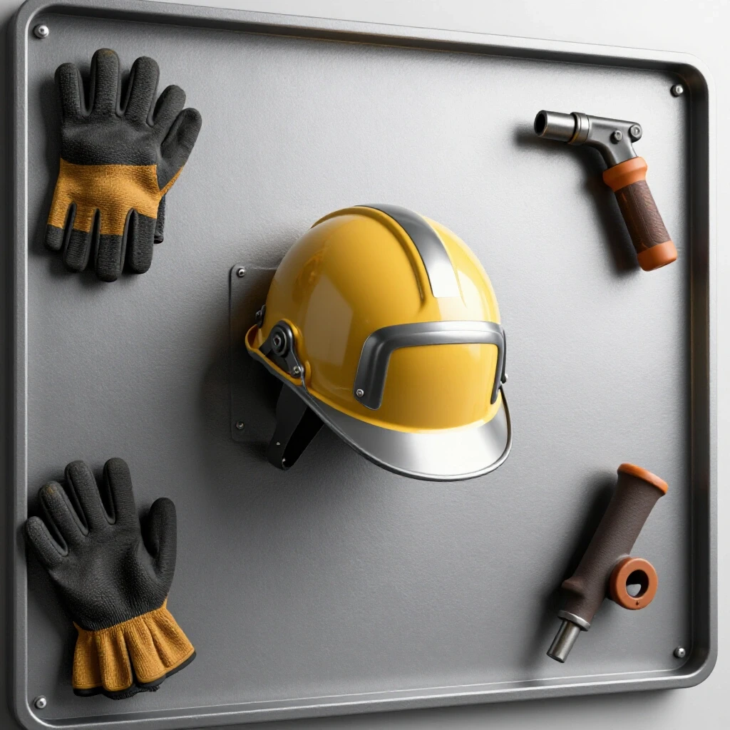
That experience taught me that custom fabrication projects are not just about melting metal together; they are about managing forces. When you build something as simple as a wall-mounted organizer for your workshop gear, the same rules apply. If you don’t account for weld shrinkage and thermal expansion, your hooks will be crooked, and the mounting plate will won’t sit flush against the wall. This guide focuses on the technical side of building a sturdy, straight rack for your welding hoods, ensuring your gear stays off the floor and protected.
Designing the Storage Rack Layout and Material Selection
Designing a storage rack layout involves choosing the right steel profiles and mapping out dimensions to ensure the structure is strong enough to hold equipment without bending. Proper planning prevents material waste and ensures the final product fits the intended space perfectly.
When I plan a project like this, I start with the weight and the “lever arm” effect. A welding helmet isn’t heavy, but when it sits on a hook six inches away from the wall, it exerts torque on the weld joint. For the main vertical spine, I prefer using 1-inch square tubing with a 1/8-inch wall thickness. For the actual arms that hold the helmets, 3/16-inch flat bar is easy to shape and weld.
- Material List for a Three-Helmet Rack:
- Main Rail: 36 inches of 1-inch square tubing (11ga or 1/8-inch wall).
- Support Arms: 18 inches of 1-inch by 3/16-inch flat bar (cut into three 6-inch pieces).
- Mounting Tabs: 4 inches of 1.5-inch flat bar (cut into two 2-inch pieces).
- Hardware: 5/16-inch lag bolts for wall mounting.
I always suggest sketching this out on a piece of cardboard first. It sounds basic, but seeing the physical footprint of your gear helps you decide the spacing. I usually space my hooks about 12 inches apart. This gives enough room so the hoods don’t bang into each other but keeps the overall rack compact.
Calculating Kerf and Preparing Accurate Cut Lists
Kerf is the width of the material removed by the cutting tool during the fabrication process. Accounting for this loss is essential for maintaining dimensional tolerances, especially when multiple small parts are cut from a single length of stock.
If you are using a standard abrasive chop saw, your kerf—the path the blade leaves behind—is roughly 3/32 to 1/8 of an inch. If you make five cuts on a single bar without accounting for that, your last piece will be over half an inch too short. I use a “kerf-inclusive” measurement style where I mark my first piece, cut it, and then measure the next piece from the fresh edge.
| Cutting Tool | Typical Kerf Width | Accuracy Level |
|---|---|---|
| Abrasive Chop Saw | 1/8 inch (3.2mm) | Moderate |
| Cold Saw | 3/32 inch (2.4mm) | High |
| Portable Band Saw | 1/16 inch (1.6mm) | High |
| Plasma Cutter | 1/16 to 1/8 inch | Low (requires grinding) |
| Angle Grinder (Thin) | 3/64 inch (1.2mm) | Moderate |
When cutting your square tubing for the main spine, ensure the ends are perfectly square. An out-of-square cut creates uneven gaps. In welding, gaps are the enemy of stability because the weld metal will fill that gap and pull the metal toward the side with the most heat as it cools. I aim for a dimensional tolerance of +/- 1/16th of an inch across the entire assembly.
Building Workshop Jigs for Repeatable Alignment
Workshop jigs are temporary fixtures that hold metal components in a fixed position during assembly. They are the only way to ensure that every arm on your rack is at the same angle and that the main frame stays flat during the tacking process.
For a project like this, you don’t need a professional welding table. You can build a simple jig using scrap angle iron and C-clamps. I like to clamp my main square tube to the edge of my workbench. Then, I use a magnetic square to hold the flat bar arms at a 90-degree angle to the tube.
- Clean your workspace and ensure the surface is flat.
- Lay down your main spine and clamp it at both ends to prevent it from bowing.
- Use a 90-degree clamping jig to position the first support arm.
- Check the alignment with a machinist square before applying any heat.
- Repeat this for all arms, ensuring the distance between them is consistent within 1/32 of an inch.
Using fixtures is about fighting the “pull.” As the weld pool cools, it shrinks. If the piece isn’t clamped down, that shrinkage will pull the arm upward or downward, leaving you with a rack that looks like it was built by someone who didn’t care about the details.
Managing Weld Sequencing to Control Thermal Distortion
Weld sequencing is the specific order in which you apply beads to a joint to balance heat input. By strategically placing welds, you can use the cooling contraction of one bead to counteract the pull of another, keeping the project straight.
This is where most garage builders run into trouble. They start at one end and weld all the way to the other. By the time they reach the end, the heat has built up so much that the entire bar has bowed like a banana. Interestingly, the side you weld first will almost always pull the metal toward it.
- The Balancing Act:
- Place a small tack on the top of the joint.
- Place a second tack on the bottom of the joint.
- Move to the next arm and repeat the process.
- Do not finish any single weld until all arms are tacked and the rack is checked for squareness.
- If the bar starts to bow, weld on the opposite side to “pull” it back into alignment.
In custom fabrication projects, I use a “back-stepping” technique. Instead of one long continuous bead, I run short 1-inch beads and skip around the project. This keeps the Heat-Affected Zone (HAZ) small and prevents the metal from reaching its elastic limit, where permanent deformation occurs.
Tacking Strategies and Structural Integrity
Tack welding involves small, temporary welds that hold the assembly together before the final beads are applied. The size and placement of these tacks determine whether the project will survive the stresses of final welding without shifting.
For 1/8-inch thick steel, your tacks should be about 1/4 inch long. If they are too small, they will crack under the stress of the metal cooling. If they are too large, they become difficult to weld over and can create lumps in your final bead. I always place my tacks at the corners of the joint where the metal is strongest.
- Tack Spacing: For a 1-inch joint, place a tack on opposite corners.
- Tack Strength: A good tack should be able to withstand a light tap from a hammer without breaking.
- Alignment Check: After tacking, use a digital angle finder or a square to verify the arms haven’t moved. If they have, you can usually “cold-set” them by gently tapping them back into place before the final weld.
I’ve seen many builders skip the tacking phase and go straight to final welds. This is a recipe for frustration. A tack is your “undo” button. It is much easier to grind away a 1/4-inch tack than it is to cut through a full 1-inch bead because your alignment was off by five degrees.
Why Weld Shrinkage Warps Square Structures
Weld shrinkage occurs because steel expands when heated and contracts as it cools. Because the weld area is localized, the surrounding cold metal resists this movement, creating internal stresses that physically bend the part.
When you weld a flat bar arm to a square tube, the weld on the top of the bar will want to pull the bar upward. This is called angular distortion. To combat this, some fabricators “preset” the joint. They might angle the arm one or two degrees in the opposite direction of the weld, knowing that the shrinkage will pull it into a perfect 90-degree angle.
| Material Thickness | Heat Input (Amps) | Expected Shrinkage (Per Inch) |
|---|---|---|
| 16 Gauge (Thin) | 40-60 | High (Warping is common) |
| 1/8 Inch (Standard) | 90-125 | Moderate |
| 1/4 Inch (Heavy) | 150-200 | Low (Higher mass resists pull) |
Understanding the physics of heat dissipation is key. Steel is a relatively poor conductor of heat compared to aluminum. This means the heat stays concentrated near the weld for longer, increasing the chance of warping. I often use “heat sinks”—thick blocks of copper or extra steel clamped near the weld—to soak up that excess energy and protect the project’s dimensions.
Final Straightening and Wall Mounting Procedures
The final phase involves checking the assembly for any remaining distortion and securing it to the workshop wall. Even with the best sequencing, some minor movement is normal, and knowing how to correct it is a vital skill for any fabricator.
Once the welding is complete and the metal has cooled to the touch (never quench it in water, as this can make the steel brittle), lay the rack against a known flat surface. If there is a slight wobble, you can use a large crescent wrench to gently tweak the arms. For the mounting tabs, ensure they are welded flat so the rack sits flush against the wall studs.
- Locate Studs: Use a stud finder to mark the 16-inch or 24-inch centers on your wall.
- Leveling: Hold the rack up and use a 2-foot level on the main spine.
- Pilot Holes: Drill pilot holes into the studs to prevent the wood from splitting when you drive in the lag bolts.
- Fastening: Use 5/16-inch by 3-inch lag bolts with washers. The washers distribute the load across the mounting tab, preventing the metal from deforming under pressure.
A gear organizer is only as good as its connection to the wall. By using lag bolts into structural studs, you ensure that the rack can handle the weight of multiple helmets, jackets, or even heavy grinding shields without sagging over time.
Advanced Layout Tips for Custom Fabrication Projects
As you move into more complex shop fixtures, you might consider using laser alignment tools or 3D-printed templates. These modern tools can help you achieve a level of precision that was once reserved for high-end machine shops.
For a simple rack, a laser level can be used to project a perfectly straight line across your workbench. This acts as a visual guide for aligning multiple arms. Additionally, if you have access to a 3D printer, you can print custom “clamping blocks” that fit over your square tubing and hold the flat bar at the exact angle you need.
- Laser Alignment: Set a laser line to mark the center of your mounting holes.
- Template Use: Use a paper template for hole locations to ensure your mounting tabs match the wall stud spacing perfectly.
- Post-Weld Logs: I keep a notebook of every build. I record the amperage I used and how much the metal moved. Over time, this data helps me predict exactly how much “pull” to expect on future projects.
Building your own shop fixtures is the best way to practice these skills. The stakes are lower than on a vehicle chassis, but the principles are identical. Every straight, square rack you build makes you a better fabricator for the next big project.
Common Mistakes to Avoid in Metal Layout
Even experienced builders can fall into traps when they are in a hurry. One of the most common errors is failing to deburr the metal after cutting. A small burr on the end of a tube can throw off your square by a fraction of a degree, which translates to a significant error over a 3-foot span.
Another mistake is “chasing the warp.” This happens when you see the metal move and immediately try to weld it back. Usually, this just adds more heat and makes the problem worse. The best approach is to let the piece cool completely before deciding how to correct a deviation.
- Don’t weld in a draft: Wind can blow away your shielding gas, leading to porous, weak welds.
- Don’t ignore the mill scale: Always grind the area to be welded down to shiny metal. Mill scale acts as an insulator and can cause inconsistent penetration.
- Don’t over-weld: For a gear rack, a 1-inch bead is plenty. Adding more weld doesn’t make it stronger; it just adds more heat and more distortion.
By focusing on these small details—clean metal, accurate tacks, and controlled heat—you will produce a storage solution that looks professional and functions perfectly. You’ll find that the more you respect the behavior of the steel, the less you have to fight it.
Frequently Asked Questions
How do I stop my square tubing from bowing when I weld on one side?
The best way to prevent bowing is to use a balanced weld sequence. If you weld on the front of the tube, immediately follow it with a weld on the back. This balances the contraction forces. Clamping the tube to a heavy, flat surface like a thick steel table also helps physically restrain the metal.
What is the best material thickness for a workshop gear rack?
For most manual welding gear, 1/8-inch (11-gauge) steel is the “sweet spot.” It is thick enough to weld easily without burning through, but light enough that the finished rack isn’t excessively heavy. For the arms, 3/16-inch flat bar provides extra stiffness to prevent sagging.
Do I really need to account for kerf on such a small project?
Yes. If you are cutting three arms at 6 inches each from one bar, you will lose about 1/4 inch to 3/8 inch of total material to the blade. If you don’t account for this, your last arm will be noticeably shorter than the others, which affects the aesthetics and the balance of the rack.
How can I tell if my weld has enough penetration?
Look for the “heat tint” on the back side of the metal. For 1/8-inch steel, you should see a slight discoloration or a small “bulge” on the opposite side of the weld. This indicates that the base metal has reached its melting point all the way through the joint.
Why did my tack weld crack as soon as it cooled?
This usually happens because the tack was too small or the metal was under too much tension. If the pieces are being forced together, the cooling tack can’t handle the stress. Make your tacks slightly larger or ensure the fitment is “neutral” (no gaps) before tacking.
Can I build this with a flux-core welder?
Absolutely. Flux-core is great for shop projects. Just be sure to clean the slag off your tacks before you weld over them. If you leave slag in the joint, it will cause inclusions and weaken the final weld.
How do I fix a rack that is already warped?
You can use “flame straightening.” By carefully heating the side opposite the warp with a torch and then letting it cool (or quenching it), you can force the metal to contract and pull itself straight. This takes practice but is a standard industrial technique.
What is the best way to paint the finished project?
First, remove all welding scale and spatter with a wire wheel or flap disc. Wipe the metal down with acetone to remove oils. Use a high-quality self-etching primer followed by a durable enamel topcoat. This prevents the rack from rusting in a humid garage environment.
How far apart should the mounting holes be?
Standard wall studs in North America are typically 16 inches apart. I recommend drilling your mounting holes 16 inches apart or 32 inches apart so you can bolt directly into the wood. Avoid using drywall anchors for metal racks, as they can vibrate loose or pull out over time.
Is it better to use angle iron or square tubing?
Square tubing is generally more resistant to twisting (torsion) than angle iron. For a rack that sticks out from the wall, square tubing provides a cleaner look and better structural rigidity for the main vertical support.
How do I ensure all the hooks are at the exact same height?
Use a “story pole” or a layout template. Mark a single piece of wood with your desired spacing and use that to mark the steel. This eliminates “cumulative error” that happens when you measure from one mark to the next. Always measure from a single “datum” or starting point.
(This article was written by one of our staff writers, Robert Kline. Visit our Meet the Team page to learn more about the author and their expertise.)