How to Build a Heavy Sheet Metal Folding Brake (DIY Plan)
I have spent thirteen years in fabrication shops, and if there is one thing I have learned, it is that steel has a memory and a mind of its own. I remember my first major custom fabrication project: a heavy-duty utility trailer. I had spent hours measuring, squaring, and clamping. I felt confident. But as I laid down the final structural beads, I watched in frustration as the rear cross-member pulled nearly half an inch out of square. The heat from the welder had physically moved the steel, a phenomenon known as weld shrinkage. This is the reality of working with metal; it is a dynamic material that reacts to temperature and stress.
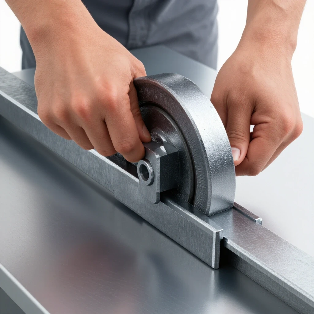
When you decide to build a manual shop tool for folding heavy-gauge plate, you are not just sticking metal together. You are creating a precision instrument that must withstand thousands of pounds of force without flexing. If your base frame bows or your hinges are misaligned by even 1/16th of an inch, your bends will be “crowned”—tighter at the ends and loose in the middle. To succeed, we have to approach the build with a strategy for managing heat and maintaining structural rigidity.
Designing the Framework for Heavy Metal Bending
This initial phase involves creating a detailed blueprint and material list to ensure all components interact correctly. It focuses on calculating kerf and choosing steel sections that can withstand the high torque required for bending 10-gauge plate. Without a solid plan, you risk wasting expensive raw materials on a tool that flexes under load.
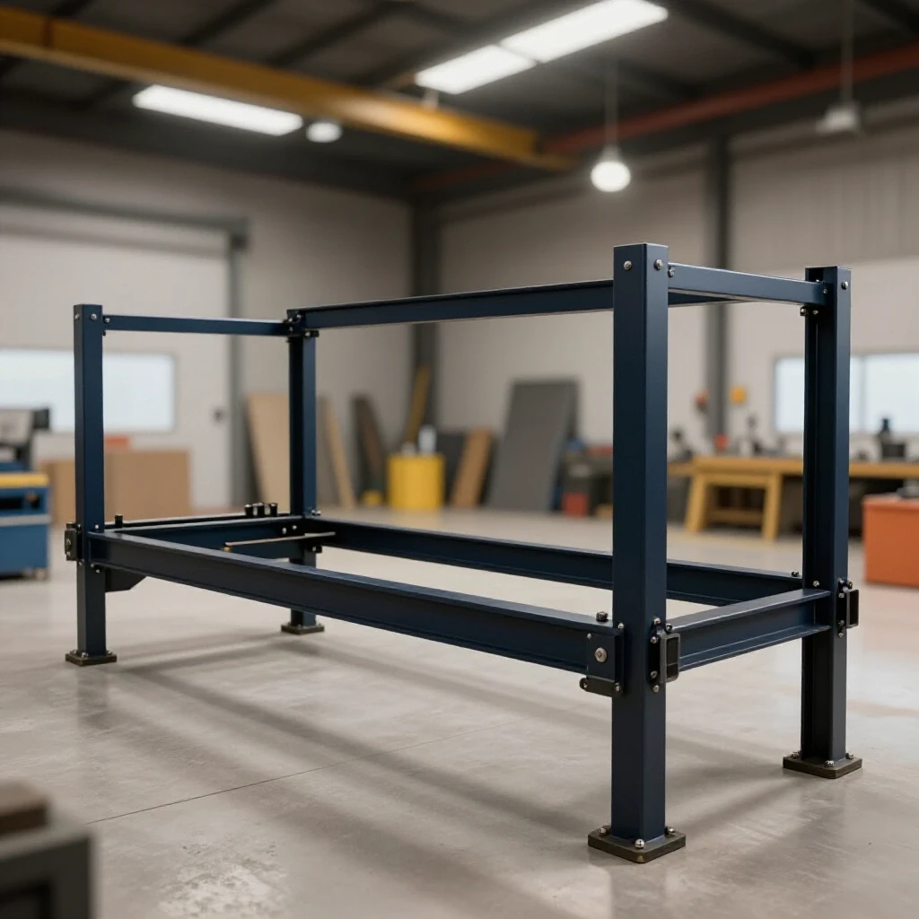
Before I strike an arc, I always start with a cut list. For a tool designed to handle 48-inch wide sheets of 10-gauge steel, the forces are immense. I recommend using 3-inch by 3-inch by 1/4-inch angle iron for the base and the bending leaf. For the clamping bar, which takes the brunt of the upward pressure, a piece of 4-inch C-channel reinforced with a vertical 1/2-inch steel plate is often necessary to prevent bowing.
Calculating Kerf and Cutting Allowances
Kerf is the width of the material removed by your cutting tool during a pass. When planning your cuts, you must account for this “lost” material to ensure your final pieces are the correct length. If you use a standard 14-inch abrasive chop saw, your kerf might be 1/8 of an inch, whereas a plasma cutter or a thin zip disc on a grinder might only remove 1/16 of an inch.
- Abrasive Saw: 1/8″ (0.125″) kerf.
- Plasma Cutter: 1/16″ to 3/32″ depending on tip size.
- Cold Saw: 3/32″ (0.093″) kerf.
- Oxy-Acetylene: 1/8″ to 3/16″ depending on travel speed.
I always mark my “keep” side of the line and cut into the waste side. In a project where the pivot points must be perfectly parallel, being off by a kerf’s width on one side will result in a crooked hinge. This leads to a tool that binds during operation.
Material Selection for Structural Rigidity
Choosing the right steel grade and shape is critical for workshop jigs and fixtures. For this build, A36 mild steel is the standard. It is weldable, predictable, and cost-effective. However, the shape of the steel matters as much as the thickness. An L-shaped angle iron is strong in one direction, but it can twist. By welding two pieces of angle iron together to form a box section for the bending leaf, you increase the torsional rigidity significantly.
| Material Type | Recommended Use | Yield Strength (psi) |
|---|---|---|
| 3″ x 3″ x 1/4″ Angle | Base Frame / Bed | 36,000 |
| 4″ C-Channel | Clamping Bar Base | 36,000 |
| 1″ Cold Rolled Round | Hinge Pivot Pins | 50,000+ |
| 1/2″ Flat Plate | Reinforcement Gussets | 36,000 |
Managing Heat Distortion and Weld Sequencing
Weld shrinkage occurs when molten metal cools and contracts, pulling the base material with it. For a long bending leaf, this can cause a “bow” that prevents straight bends. Controlling this requires specific sequencing and physical restraints to ensure the finished tool remains flat across its entire length.
One of the biggest mistakes I see in custom fabrication projects is “chasing the weld.” This happens when a builder welds one side of a joint completely, causing the part to pull, and then tries to weld the other side to pull it back. It rarely works. Instead, we use a weld sequencing layout that distributes heat evenly across the structure.
The Physics of Angular Pull
When you lay a fillet weld in a T-joint, the top of the weld bead contracts more than the root. This creates an angular pull, drawing the two pieces of metal toward the weld. On a four-foot-long bending leaf, even a tiny amount of pull at the joint can result in a 1/4-inch bow over the total span. To combat this, I use heavy-duty F-clamps and “strongbacks”—temporary pieces of thick scrap steel tacked to the project to hold it straight while the structural welds cool.
Implementing a Balanced Weld Sequence
The key to a straight build is the “back-step” method. Instead of running one long bead from left to right, you break the weld into 2-inch segments. You start 2 inches in from the end and weld toward the edge. Then, you move back another 2 inches and weld toward the start of your first bead. This prevents the heat from building up in one continuous wave, which is the primary cause of warping.
| Sequence Step | Action | Purpose |
|---|---|---|
| 1. Tacking | 1/4″ tacks every 4 inches | Secure alignment without excessive heat. |
| 2. Root Pass | 2″ back-step beads | Establish structural base with minimal pull. |
| 3. Cooling | Wait until hand-touch warm | Allow stresses to stabilize. |
| 4. Final Pass | Opposite side of joint | Counter-act the pull from the first pass. |
Constructing the Pivot and Hinge Assembly
The hinges are the heart of any folding tool, acting as the fulcrum for the bending force. Precision alignment here is non-negotiable; even a 1/32-inch deviation can cause binding or uneven pressure across the workpiece. This section covers how to create a heavy-duty pivot that can handle the leverage of a five-foot handle.
For a heavy-duty bender, I avoid store-bought hinges. They aren’t designed for the radial loads we are applying. Instead, I use a “pin and sleeve” design. This involves a 1-inch diameter cold-rolled steel rod acting as the pin, and thick-walled DOM (Drawn Over Mandrel) tubing as the sleeve. DOM tubing is preferred because it has no internal weld seam, providing a smooth, tight fit for the pin.
Setting the Pivot Point Offset
The location of the hinge pin center is the most critical measurement in the entire build. To get a clean 90-degree bend, the center of the pivot must be exactly aligned with the “break line” where the base plate meets the bending leaf. If the pivot is too high, the leaf will jam against the metal. If it is too low, the bend will be “soft” and radiused rather than sharp.
- Vertical Alignment: The center of the pin should be flush with the top surface of the base bed.
- Horizontal Alignment: The pin center should be exactly at the gap between the bed and the leaf.
- Gap Allowance: I leave a 1/16-inch gap between the moving leaf and the fixed bed to allow for the thickness of the weld bead and thermal expansion.
Using an Alignment Jig for Hinges
To ensure both hinges are perfectly “in phase” (on the same centerline), I never weld them separately. I use a single long piece of 1-inch rod that spans the entire width of the bender. I slide all the hinge sleeves onto this single rod, clamp them into position, and tack them. This ensures that even if my frame is slightly off, the hinges are perfectly concentric with each other. Once the tacks are secure and I’ve tested the movement, I can cut the long rod into two separate pins or leave it as a full-width axle for maximum strength.
Fabricating the Clamping Bar and Pressure System
The clamping bar holds the sheet metal firmly against the base during the fold. It must be rigid enough to resist lifting or bowing under the pressure of a 90-degree bend in thick material. If the bar flexes, the sheet metal will slip, resulting in an inaccurate bend or a ruined workpiece.
When you pull the handle to bend 10-gauge steel, the metal wants to push the clamping bar upward. On a 48-inch span, the center of that bar will try to bow up. To prevent this, I use a “tensioner” or a “truss” design. By welding a piece of 1/2-inch plate vertically to the top of the clamping bar, you increase its resistance to bending by a factor of four.
Pressure Mechanisms: Threaded Rod vs. Cam Locks
You need a way to apply hundreds of pounds of clamping force quickly and evenly. 1. Threaded Rod: Using 3/4-inch Grade 8 all-thread at each end is the simplest method. It provides immense pressure but is slow to operate. 2. Cam Locks: These use an eccentric circle to pull the bar down with a lever. They are much faster but require precise machining to ensure they apply enough force for heavy gauges. 3. Hydraulic Bottle Jacks: For extremely heavy builds, some fabricators mount small 2-ton bottle jacks at each end of the clamping bar.
In my experience, the threaded rod is the most reliable for a garage-built tool. I weld a large “T-handle” to the top of the nuts so I can tighten them by hand without needing a wrench every time I move the workpiece.
Maintaining Parallelism under Load
The clamping bar must stay parallel to the bed as it moves up and down. I achieve this by building “guides” on the side of the frame. These are simply vertical pieces of steel plate that the ends of the clamping bar slide between. I keep the tolerance tight—about 1/32 of an inch of play—to ensure the bar doesn’t shift forward or backward when I start the bend.
Step-by-Step Assembly and Final Squaring
This log tracks the actual construction process, from the first tack weld to the final structural pass. It emphasizes the use of temporary fixtures to maintain dimensional tolerances. Following a logical sequence prevents you from painting yourself into a corner—or worse, welding a part that prevents you from installing the hinges later.
Phase 1: The Base Frame
Start by laying out your main bed on a flat surface. If your workbench isn’t perfectly flat, use shims and a long straightedge. * Cut the main bed (angle iron or C-channel). * Tack the end legs or mounting plates. * Check for Square: Measure diagonally from corner to corner. If the measurements are within 1/16th of an inch, proceed. * Run 2-inch beads on the underside first to pull the metal “down” against the table.
Phase 2: The Bending Leaf
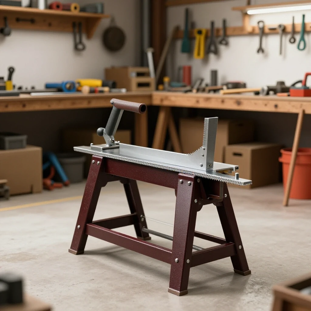
The leaf needs to be heavy. I often fill the void of the angle iron with a piece of flat bar to add mass. * Clamp the leaf to the base with a 1/16-inch spacer (a piece of scrap sheet metal works well). * Align your hinge sleeves using the “long rod” method mentioned earlier. * Tack the hinges to the base and the leaf. * The Swing Test: Before final welding, swing the leaf through its full 120-degree motion. It should move with one finger and have no “tight spots.”
Phase 3: The Clamping Bar
- Set the bar on top of the bed.
- Install your vertical guides and threaded rod assemblies.
- Ensure the “nose” of the clamping bar (the part that the metal bends around) is ground to a slight radius. A sharp 90-degree edge on the clamping bar can actually weaken the sheet metal by creating a “stress riser” at the bend.
Correcting Heat Distortion and Final Tuning
Even with the best weld sequencing, some movement is inevitable. Once the tool is fully welded, you need to perform a “post-weld alignment log” to identify and correct any issues. This is where the difference between a “good” tool and a “great” tool is made.
If the bending leaf has bowed slightly toward the welds, you can sometimes “flame straighten” it. This involves heating a small spot on the opposite side of the weld with an oxy-acetylene torch. As the spot cools, it contracts and pulls the metal back toward straight. However, this is an advanced technique. For most builders, it is safer to use a heavy hydraulic jack and a chain to physically “cold-bend” the frame back into alignment.
Actionable Benchmarks for Accuracy
- Straightness: A 4-foot straightedge should not show a gap larger than 1/32-inch anywhere along the bed.
- Hinge Play: There should be zero perceptible “wiggle” in the hinges. If there is, your hinge pins are too small for your sleeves.
- Bending Effort: Bending a 12-gauge piece of steel at 24 inches wide should be possible with one hand on a 3-foot handle. If it requires your whole body weight, your leverage or pivot geometry is inefficient.
| Feature | Tolerance Goal | Detection Method |
|---|---|---|
| Bed Flatness | +/- 0.031″ | Machinist’s Straightedge |
| Hinge Alignment | +/- 0.015″ | Calipers / Feeler Gauges |
| Squareness | +/- 0.062″ | Diagonal Measurements |
| Clamp Parallelism | +/- 0.020″ | Dial Indicator or Spacer Block |
Frequently Asked Questions
What is the best way to prevent the bending leaf from bowing during welding? The most effective method is to “pre-bend” the part in the opposite direction before welding. By clamping the leaf to your table with a 1/8-inch shim in the center and pulling the ends down, you create a reverse bow. When the welds contract, they pull the leaf back to a straight position.
Can I use standard door hinges for a light-duty bender? I strongly advise against it. Even for thin 22-gauge metal, the forces at the pivot point are surprisingly high. Standard hinges have too much internal “slop,” which leads to inaccurate bends. Always use a pin-and-sleeve design or heavy-duty weld-on bullet hinges.
How do I calculate the “bend allowance” for my sheet metal? Bend allowance is the amount of metal consumed by the radius of the bend. For a standard 90-degree bend in mild steel, a good rule of thumb is to add 1/3 of the material thickness to your measurement. If you are bending 1/8-inch steel, your “lost” material in the bend is roughly 0.041 inches.
Why are my bends “crowning” in the middle? Crowning happens when the clamping bar or the bending leaf flexes in the center. This means the pressure in the middle is lower than at the ends. To fix this, you must reinforce the center of your clamping bar with a vertical “stiffener” or add a secondary tensioning bolt in the middle of the tool.
What welding process is best for this project? MIG (GMAW) is excellent for speed and filling gaps, but TIG (GTAW) offers the best heat control. If you are using a standard 110v/220v MIG welder, ensure you are getting deep penetration on the 1/4-inch plate. I prefer using a 7018 stick electrode for the hinges because of its high ductability and strength.
How thick of a material can I realistically bend with a manual tool? With a 4-foot wide bender built from 1/4-inch structural steel, you can comfortably bend 12-gauge mild steel. You can do 10-gauge in shorter widths (up to 24 inches). Bending 1/8-inch or 10-gauge at full 4-foot width requires significant leverage and a very heavy frame.
Do I need to heat the metal before bending? No, this tool is designed for “cold forming.” Heating the metal (hot-bending) changes its molecular structure and can make it brittle. If the metal is too thick to bend cold, you need more leverage or a stronger tool.
How do I stop the bender from sliding across the floor? A heavy-duty bender should be bolted directly to the floor or a very heavy, dedicated stand. If you are working in a garage where you can’t bolt to the floor, build a wide “H-frame” base and stand on the base while you pull the handle to use your own body weight as an anchor.
What is the “nose radius” and why does it matter? The nose radius is the curve on the edge of the clamping bar that the metal wraps around. A sharp edge will “score” the metal, making the bend weak. A radius of approximately 1 to 1.5 times the material thickness is ideal for maintaining structural integrity in the bend.
How do I maintain the tool to prevent rust? Raw steel will rust quickly in a garage. After finishing the build, wipe the entire tool down with acetone and apply a coat of industrial enamel paint. Leave the “working surfaces” (where the metal slides) unpainted and coat them with a thin layer of paste wax or dry silicone lubricant to prevent corrosion without making the tool greasy.
Building your own shop equipment is a milestone for any fabricator. It requires you to think like an engineer and execute like a craftsman. By focusing on weld sequencing, material selection, and precise hinge geometry, you can create a tool that performs as well as any industrial unit. Remember, the goal isn’t just to finish the project; it’s to build a tool that remains straight and true for years of service. Take your time with the layout, respect the heat of the weld, and always double-check your square.
(This article was written by one of our staff writers, Robert Kline. Visit our Meet the Team page to learn more about the author and their expertise.)