How to Build a Storage Rack for Sorting Fasteners (DIY Plan)
I have spent thirteen years in shops, and if there is one thing I have learned, it is that steel has a mind of its own. I remember my first major project—a custom utility trailer frame. I had measured every piece to the sixteenth of an inch. I clamped it down, started welding, and by the time I finished the last bead, the entire frame had pulled into a three-inch diamond. It was a humbling lesson in the physics of heat. Since then, I have approached every custom fabrication project with a focus on controlling that movement. Building a custom organization system for your shop’s hardware is the perfect project to practice these precision techniques. It requires repeatable cuts, perfectly square joints, and a weld sequence that keeps the frame from twisting into a pretzel.
Designing the Structural Foundation for Hardware Storage
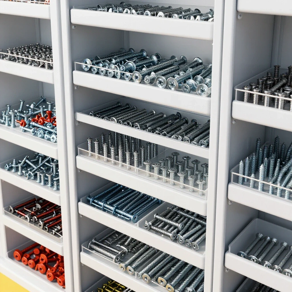
Designing the structural foundation involves selecting raw steel profiles and calculating load-bearing capacities for a vertical storage unit. This phase ensures the final build can support the substantial weight of bulk steel bolts and nuts without sagging or tipping, while also accounting for the specific footprint available in your shop.
When you start planning a heavy-duty hardware rack, you have to consider the density of your cargo. A single bin of half-inch grade 8 bolts weighs significantly more than a bin of washers. For a standard five-foot-tall rack, I typically recommend 1-inch or 1.25-inch square tubing with a 1/8-inch wall thickness. This provides enough rigidity to prevent the uprights from bowing under a full load. If you use thinner 16-gauge material, you might save money, but you will likely see the shelves sag over time.
Before you buy your steel, draw a full-scale layout on your shop floor or a large piece of plywood. This allows you to visualize the spacing between the bins. You need enough “knuckle room” to reach into a bin and grab a bolt without hitting the shelf above it. I usually aim for a 2-inch clearance between the top of the bin and the bottom of the next rail.
Selecting Materials for Durability and Weight
Material selection is the process of choosing the right steel shapes and thicknesses based on the expected total load and the welding process you intend to use. Choosing the right stock prevents structural failure and makes the welding process much easier by providing a consistent heat-sink for your beads.
- Square Tubing (1″ x 1″ x 1/8″): Ideal for the main vertical uprights and the base frame. It resists twisting better than angle iron.
- Angle Iron (1″ x 1″ x 1/8″): Excellent for the horizontal rails that hold the bins. The “L” shape provides a natural lip to catch the back of a storage container.
- Flat Bar (1/8″ thick): Useful for creating custom tabs or floor mounts to keep the unit from tipping.
Precision Cutting and Material Preparation
Precision cutting and material preparation involve more than just pulling a trigger on a saw; it requires accounting for the width of the blade and ensuring every end is perfectly square. This stage is where most dimensional errors begin, often leading to gaps that cause excessive weld shrinkage and frame distortion.
One of the most common mistakes I see is the “stacking error.” If you need ten pieces at 12 inches each, and you mark them all on a single 120-inch bar before cutting, your last piece will be short. This happens because the saw blade removes a small amount of metal with every pass. This is known as the kerf. To get an accurate frame, you must mark, cut, and then mark the next piece from the new edge.
Understanding and Calculating Kerf Allowances
Kerf is the width of the material removed by the cutting tool during the fabrication process. Failing to account for this 1/16 to 1/8 of an inch per cut will result in a frame that is too small, leading to fitment issues when you try to slide your bins into place.
| Tool Type | Average Kerf Width | Dimensional Impact per 10 Cuts |
|---|---|---|
| Abrasive Chop Saw | 1/8″ (0.125″) | 1.25 inches lost |
| Cold Saw | 3/32″ (0.093″) | 0.93 inches lost |
| Portable Bandsaw | 1/32″ (0.031″) | 0.31 inches lost |
| Plasma Cutter | 1/16″ (0.062″) | 0.62 inches lost |
I prefer using a bandsaw for these projects. The thinner kerf means less wasted material and much cleaner cuts. After every cut, I use a square and a file to remove the burr. A burr might only be 0.010 inches thick, but if you have ten joints, those burrs add up to a significant alignment error.
Building Layout Jigs for Square Assembly
Building layout jigs involves creating a temporary physical boundary or fixture that holds your workpieces in the exact desired orientation during the assembly process. These shop-made tools act as a “third hand,” ensuring that your 90-degree corners stay square while you apply heat and pressure.
I never trust a magnet to hold a frame square during welding. Magnets are great for holding a piece in place while you reach for your pliers, but they cannot resist the force of a cooling weld. Instead, I build a simple jig on my welding table. I use scrap pieces of angle iron or square tubing clamped to the table to create a “pocket” for the frame corners.
Creating a Simple Corner Fixture
A corner fixture is a basic assembly tool made from two pieces of straight material joined at a perfect 90-degree angle. By clamping your project pieces into this fixture, you force the metal to maintain its shape even as the heat tries to pull the joint inward.
- Find a flat surface. If your table isn’t flat, your rack will wobble.
- Clamp two pieces of heavy square tubing to the table at a 90-degree angle. Use a reliable machinist’s square to verify this.
- Slide your project pieces into this “L” shape and clamp them firmly to the table and the jig.
- Check the diagonals. For a rectangular frame, the distance from the top-left corner to the bottom-right corner must be identical to the top-right to bottom-left distance.
Strategic Tack Welding for Dimensional Stability
Strategic tack welding is the practice of placing small, temporary welds at key points to hold an assembly together before the final beads are run. Proper tacking prevents the metal from moving during the heavy welding phase and allows for minor adjustments if a measurement is slightly off.
When I started out, I used to put one big tack on a corner and start welding. That is a recipe for a crooked rack. Now, I use at least two tacks per joint, placed on opposite sides of the tube. These tacks should be about 1/8-inch in diameter. If you place a tack on the inside of a corner only, the cooling metal will pull the joint closed, and you will lose your 90-degree angle.
The Science of Weld Shrinkage
Weld shrinkage occurs because molten steel occupies more volume than solid steel. As the weld pool cools and solidifies, it contracts, exerting thousands of pounds of force on the surrounding metal. Understanding this “pull” allows you to place tacks in a way that counteracts the movement.
- Angular Pull: The weld pulls the two pieces of metal toward the side where the bead is placed.
- Longitudinal Shrinkage: The weld pulls the metal along the length of the bead, which can bow a long tube.
- Transverse Shrinkage: The weld pulls the two pieces closer together across the joint.
To combat this, I always “pre-set” my joints if I am not using a heavy jig. This means I might gap the joint 1/16-inch wider on the side I expect to pull the most. However, for a workshop bin rack, the best approach is heavy clamping and symmetrical tacking.
Managing Heat Distortion through Sequence Control
Managing heat distortion through sequence control is the method of planning the order and direction of your welds to balance the internal stresses created by heat. By jumping from one side of the project to the other, you allow heat to dissipate and prevent one side of the frame from pulling more than the other.
If you weld all the joints on the left side of your frame and then move to the right, the left side will have already cooled and contracted, pulling the frame out of alignment. I use a “staggered” sequence. I weld the top-left corner, then the bottom-right, then the top-right, and finally the bottom-left. This distributes the heat evenly across the entire structure.
Weld Sequence Tracking Chart
Using a tracking chart helps you maintain a consistent pattern, which is especially important when you are welding dozens of small rails for a hardware organization system.
| Step | Location | Side | Purpose |
|---|---|---|---|
| 1 | Top Left Corner | Front | Initial anchor |
| 2 | Bottom Right Corner | Front | Balancing the pull |
| 3 | Top Right Corner | Front | Secondary anchor |
| 4 | Bottom Left Corner | Front | Completing the front face |
| 5 | Flip Frame | – | Relieve stress |
| 6 | Repeat 1-4 | Back | Final structural tie-in |
I also recommend “back-stepping” your welds. Instead of starting at the edge and welding toward the center, start an inch away from the edge and weld toward it. This helps reduce the concentration of heat at the ends of your tubing, where distortion is most likely to occur.
Fabricating Angled Rails for Bin Access
Fabricating angled rails involves cutting and mounting the horizontal supports at a specific pitch so that the bins tilt forward. This angle makes it easier to see the contents of the bins and allows you to pull out a handful of fasteners without removing the entire container from the rack.
Most plastic or metal bins have a small lip on the back. To hang these effectively, your rails should be tilted at an angle of 15 to 20 degrees. I use a digital angle finder to set my first rail and then create a “spacer block” from a piece of scrap wood or metal. This spacer ensures that every subsequent rail is at the exact same height and angle as the first one.
Ensuring Symmetry Across the Uprights
Symmetry is vital for the bins to sit level. If one side of a rail is 1/8-inch higher than the other, the bin will sit crooked and may even slide off the rail under vibration.
- Mark the height of every rail on both front uprights using a height gauge or a very steady tape measure.
- Clamp the horizontal rail to the uprights using C-clamps.
- Check the level of the rail across its width.
- Tack the top of the rail, then the bottom, before moving to the other side.
- Measure the distance between the rails at both ends to ensure they are parallel.
Final Straightening and Finishing
Final straightening and finishing are the last steps where you correct any minor warping that occurred despite your best efforts and prepare the metal for a protective coating. This phase ensures the project looks professional and functions correctly, with all bins sliding in and out smoothly.
Even with the best jigs, you might find a slight twist in your rack. If the rack wobbles on the floor, you can often “cold-straighten” it. I sometimes place a small shim under the high leg and apply weight to the opposite corner to nudge the steel back into place. For more severe warps, you can use a torch to heat the side opposite of the weld pull, which can help pull the metal back as it cools.
Surface Prep and Coating
Before you load your new rack with hundreds of pounds of hardware, you need to protect the steel from rust. Shop environments are often humid, and raw steel will begin to oxidize within days.
- Grinding: Use a flap disc (60 or 80 grit) to smooth out your welds and remove any spatter.
- Degreasing: Use acetone or a dedicated wax and grease remover to clean the steel. This is the most important step for paint adhesion.
- Priming: Use a high-quality self-etching primer.
- Topcoat: A hammered-finish spray paint is great for shop furniture because it hides minor imperfections in the metal and the welds.
Actionable Build Checklist
- Verify the Cut List: Ensure all matching pieces (like the four uprights) are exactly the same length.
- Square the Ends: Use a square to check every cut; a 1-degree error at the base becomes a 1-inch error at the top.
- Setup the Jig: Secure your base frame to a flat table using heavy-duty clamps.
- Tack Weld: Apply 1/8-inch tacks to all corners, checking squareness after every two tacks.
- Sequence the Final Welds: Follow a diagonal pattern to distribute heat.
- Install Rails: Use a spacer block to maintain consistent height and angle for all bin supports.
- Check for Twist: Ensure the rack sits flat on the floor before final painting.
Frequently Asked Questions
How do I prevent the 1/8-inch wall tubing from blowing through during welding? Focus your arc on the thicker part of the joint or the corner. If you are using a MIG welder, keep a short wire stick-out and use a “push” technique to keep the heat moving forward rather than digging deep into one spot.
What is the best way to ensure the rack doesn’t tip over? Always design the base to be wider than the top. I also recommend welding small “feet” with holes in them to the bottom of the uprights so you can bolt the rack directly to the shop floor.
Can I use a flux-core welder for this project? Yes, but be prepared for more cleanup. Flux-core produces more spatter and a slag coating. Use a wire brush or a chipping hammer to clean every weld before you move on to the next, as you don’t want to trap slag in your final beads.
Why did my frame pull into a diamond shape even though I used clamps? You likely didn’t have enough clamps, or your tacks were too small. The force of a cooling weld can easily bend a standard C-clamp. Use heavy-duty F-style clamps and ensure you have tacks on all sides of the joint before doing a full pass.
How much weight can a 1-inch square tube rack hold? If built with 1/8-inch wall thickness and properly braced, a four-legged rack can easily support 500 to 800 pounds of hardware. The limiting factor is usually the strength of the floor or the stability of the base.
What angle should I use for the bins? A 15-degree angle is standard. It provides a good balance between visibility and security. If the angle is too steep (over 30 degrees), the bins might slide off when they are full of heavy bolts.
Should I weld the rails all the way around? For a hardware rack, a 1-inch weld on the top and bottom of each rail-to-upright joint is usually sufficient. Full perimeter welds on every rail add unnecessary heat and will likely cause the uprights to bow.
How do I fix a leg that is 1/4-inch off the ground? You can weld a threaded nut into the bottom of the leg and use a bolt as an adjustable leveling foot. This is much easier than trying to bend the entire frame back into alignment.
What is the best way to mark my steel for cutting? For high precision, use a carbide-tipped scriber. It creates a much finer line than a Sharpie, which can be 1/16-inch wide. A thinner line means a more accurate cut.
Do I need to worry about the “heat-affected zone” (HAZ)? In thin-wall tubing, the HAZ is where the metal is most likely to bend. Keep your welds small and your travel speed consistent to minimize the size of the HAZ and reduce overall distortion.
Building your own hardware organization system is more than just a storage project; it is a masterclass in metal control. By respecting the physics of heat and taking the time to build proper fixtures, you ensure that your finished rack is as straight and sturdy as the day you designed it. Take your time with the layout, watch your weld sequence, and you will end up with a piece of shop furniture that lasts a lifetime.
(This article was written by one of our staff writers, Robert Kline. Visit our Meet the Team page to learn more about the author and their expertise.)